EP0362586B1 - Stromlinienförmiges Gerät zur Messung des Freibords - Google Patents
Stromlinienförmiges Gerät zur Messung des Freibords Download PDFInfo
- Publication number
- EP0362586B1 EP0362586B1 EP89116984A EP89116984A EP0362586B1 EP 0362586 B1 EP0362586 B1 EP 0362586B1 EP 89116984 A EP89116984 A EP 89116984A EP 89116984 A EP89116984 A EP 89116984A EP 0362586 B1 EP0362586 B1 EP 0362586B1
- Authority
- EP
- European Patent Office
- Prior art keywords
- housing
- water
- chamber
- freeboard
- stick
- Prior art date
- Legal status (The legal status is an assumption and is not a legal conclusion. Google has not performed a legal analysis and makes no representation as to the accuracy of the status listed.)
- Expired - Lifetime
Links
- XLYOFNOQVPJJNP-UHFFFAOYSA-N water Substances O XLYOFNOQVPJJNP-UHFFFAOYSA-N 0.000 claims abstract description 43
- 239000000463 material Substances 0.000 claims abstract description 7
- 238000000926 separation method Methods 0.000 claims abstract description 4
- 238000005259 measurement Methods 0.000 claims description 7
- 238000004891 communication Methods 0.000 claims description 4
- 239000012530 fluid Substances 0.000 claims description 4
- 239000002657 fibrous material Substances 0.000 claims description 3
- 238000012856 packing Methods 0.000 claims description 3
- 230000000087 stabilizing effect Effects 0.000 claims 2
- 230000001154 acute effect Effects 0.000 claims 1
- 238000000034 method Methods 0.000 description 4
- 239000004033 plastic Substances 0.000 description 4
- 239000003643 water by type Substances 0.000 description 3
- 229910052782 aluminium Inorganic materials 0.000 description 2
- XAGFODPZIPBFFR-UHFFFAOYSA-N aluminium Chemical compound [Al] XAGFODPZIPBFFR-UHFFFAOYSA-N 0.000 description 2
- 229910052751 metal Inorganic materials 0.000 description 2
- 239000002184 metal Substances 0.000 description 2
- 239000011148 porous material Substances 0.000 description 2
- 241000251468 Actinopterygii Species 0.000 description 1
- 238000004026 adhesive bonding Methods 0.000 description 1
- 230000002411 adverse Effects 0.000 description 1
- 230000007812 deficiency Effects 0.000 description 1
- 238000013461 design Methods 0.000 description 1
- 238000005553 drilling Methods 0.000 description 1
- 230000000694 effects Effects 0.000 description 1
- 230000008030 elimination Effects 0.000 description 1
- 238000003379 elimination reaction Methods 0.000 description 1
- 239000004744 fabric Substances 0.000 description 1
- -1 for example Substances 0.000 description 1
- 238000012986 modification Methods 0.000 description 1
- 230000004048 modification Effects 0.000 description 1
- 230000000704 physical effect Effects 0.000 description 1
- 230000000630 rising effect Effects 0.000 description 1
- 239000012780 transparent material Substances 0.000 description 1
- 230000000007 visual effect Effects 0.000 description 1
- 239000002023 wood Substances 0.000 description 1
Images

Classifications
-
- B—PERFORMING OPERATIONS; TRANSPORTING
- B63—SHIPS OR OTHER WATERBORNE VESSELS; RELATED EQUIPMENT
- B63B—SHIPS OR OTHER WATERBORNE VESSELS; EQUIPMENT FOR SHIPPING
- B63B39/00—Equipment to decrease pitch, roll, or like unwanted vessel movements; Apparatus for indicating vessel attitude
- B63B39/12—Equipment to decrease pitch, roll, or like unwanted vessel movements; Apparatus for indicating vessel attitude for indicating draught or load
Definitions
- the present invention relates to gauging devices, and more particularly to devices for measuring freeboard of ships, barges or other vessels carrying various amounts of cargo.
- the object of the present invention is to provide a device and method for measuring the change in freeboard of a barge or other vessel, which will be indicative of a varying amount of cargo under still, as well as adverse water conditions, wherein currents or choppy waters usually prevent obtaining accurate freeboard readings.
- the freeboard measuring device of the present invention overcomes deficiencies of the prior art and solves its problems in a simple and straightforward manner as described in claim 1.
- the device preferably comprises other features as further disclosed in claims 2 to 10.
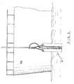
- Figure 1 is a front view of the freeboard measuring device in accordance with the present invention.
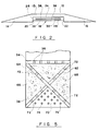
- Figure 2 is a cross-sectional view taken along lines 2-2 of Figure 1.
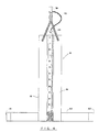
- Figure 3 is a perspective view of a freeboard measuring device in accordance with the present invention in use.
- Figure 4 is a front view of the freeboard measuring device in its alternative embodiment.
- the freeboard measuring device is generally designated by numeral 10 and comprises a central portion 12, the first fin 14 and a second fin 16 integrally connected to the central portion 12.
- the central portion 12 has a substantially rectangular cross-section, while the fins 14 and 16 have a substantially triangular cross-section, with the bases of the triangles integrally connected to the central portion 12.
- the fins 14 and 16 have a cross-section of right triangular shape, although other suitable triangular forms can be utilized, but one that produces the least overall thickness is most desirable. Outermost edges of the fins 14 and 16 are sharpened to offer less resistance to water flow.
- the central portion 12 has a recessed part 18 cut throughout its length and defined by a base wall 20 of the fin 14 and a base wall 22 of the fin 16.
- the innermost wall 24 of the recessed part 18 is in substantially perpendicular relationship to the walls 20 and 22.
- a centrally located chamber 26 of the central portion 12 is defined by the walls 24, portions of walls 20 and 22 and a recessed wall 28, which extends perpendicularly to the walls 20 and 22 and substantially parallel to the wall 24.
- the wall 28 is preferably made of a transparent material, such as high impact plastic, or other similar material having similar physical properties, the purpose of which will be explained in more detail hereinafter.
- the chamber 26 is designed to accommodate a gauging stick 30 which is lowered through an open top 32 of the chamber 26 to a distance down the chamber and rests, with its lower end on a separation wall 34, which traverses the chamber 26 in its lower part.
- the wall 34 is provided with a plurality of openings 36 in order to allow fluid communication between the lower chamber portion 38 and upper chamber portion 39.
- the transparent wall 28, in its lowermost part, on the level of portion 38 of the chamber 26 is provided with a plurality of ports 40 which allow fluid communication between the interior of the chamber 38 and exterior of the device 10.
- a packing of fibrous material 42 is placed in the chamber, substantially filling the confines thereof, still not impeding the flow of water from lower chamber 38, through the openings 36, into the upper chamber 39.
- An alternative, or additional, method of preventing turbulence of water in the lower chamber 38 provides for the use of an X-shaped insert 62, with the spaces 62, 64, 66, and 68 between the insert parts being filled with a similar packing of fibrous material, while additional ports 72 are made in the insert 62 itself in order to allow free flow of water from the exterior of the device 10 into the lower center section 70 of chamber 38 through ports 74, and from there through the sections 64, 66 and 68 into the chamber 39 through ports 36.
- the transparent wall 28 made of clear plastic, for example, allows easy drilling of ports 40 and 74 and allows visual observation of the gauging stick while the number of ports 48 and 74 is adequate for rapid filling of the upper chamber without turbulence. Additionally, the rate of chamber filling with water can be easily observed, and any blockage of openings or parts can be observed and rectified, if need be. However, other materials, such as aluminum can be used for this purpose.
- the chamber 39 has a depth approximating or slightly greater than the thickness of the gauging stick 30 to make the device 10 even more streamlined and the bases of fins are substantially equal to the depth of portion 12.
- the gauging stick 30 has a bottom edge 44 which can be concave or jagged in shape, so as not to obstruct openings 36 and impede free fluid communication between the chambers 38 and 39.
- the gauging stick 30 is calibrated on one side so that "O" points corresponds to O′ - O ⁇ on an oil gauging tape measure which is used in conjunction with the freeboard measuring device.
- the other vertically oriented portion of the gauging stick 30 is covered by a strip 46 made of porous material, such as for example, rubber, which can retain, at least temporarily, a water mark, which is easily observed upon withdrawing of the gauging stick 30 from the chamber 39.
- the device can be suspended from a vessel 50 by flexible means 48 in the form of an interlock chain, or other flexible material, and an oil gauging tape, in order to facilitate lowering and withdrawal of the measuring device from the vessel.
- a flexible line 52 such as plastic covered metal fish line can be attached to the top of the dipstick 30 and oil gauging tape 54 which allows for easy removal and replacement of the dipstick 30 within the chamber 39 without the possibility of dropping the dipstick overboard.
- the provision of the recess 18 in which the recessed wall 28 is positioned protects the transparent wall from damage by contact with other vessels, while always allowing a free flow of water into the chamber 38.
- a plug means 49 can be inserted in the upper top 32 of the chamber 39, surrounding the gauging stick 30, thus ensuring a still further advancement in accurate readings on the gauging stick.
- the material from which the portions 12, 14 and 16 are made be rust-proof, lightweight and still durable enough to withstand possible impact on the gauging device with a vessel hull without damaging the device.
- Such material as aluminum was found suitable for these purposes.
- the plastic wall 28 can be secured within the recess 18 by gluing or bolting, or other similar method ensuring fixed position of the wall 28 in relation to the walls 20 and 22 and providing water tight line of attachment.
- the device 10 is provided with streamlined characteristics, allowing it to retain its vertical orientation without being swept downstream by strong water current.
- the flat back plate 13 of the central portion 12 allows to bring the device 10 in close proximity to the vessel and does not present any additional obstacle to the water current in which the vessel freeboard is being measured.
- a vessel Under certain conditions, a vessel can be listed severely to one side and the device 10 is rotated about its vertical axis, turning slowly in circles. Under such circumstances, accurate measurements are rather difficult to obtain.
- a flat transverse bar 60 is securedly attached in perpendicular relationship to the vertical axis of the device 10, to the bottom portion thereof. It is centered about the axis and its outward edges 61 and 62 are sharpened in order to make the bar itself streamlined, by offering less resistance to a water current.
- the longitudinal dimensions of the bar can be varied depending on conditions of different areas.
- the flat bar 60 is caught by the water current and moves the device 10 to the side of the barge, while retaining it in a vertical orientation.
- the lateral dimension of the fins 14 and 16 is substantially greater than the lateral width of the central portion 12 to allow for a well-balanced freeboard measuring device which is streamlined and not affected by water conditions with swift currents and/or choppy waters.
- the bar 60 becomes specially convenient under certain conditions, by preventing rotational movement of the device 10 about its vertical axis.
- Operation of the device 10 is similar to the operation of the device disclosed in U. S. Patent No. 4,712,305, the disclosure of which is incorporated herewith by reference.
- the strip 46 can be wiped dry and procedures a - d above repeated at the next desired location for average freeboard readings at much faster pace than when using chalk or a water seeking paste.
Landscapes
- Chemical & Material Sciences (AREA)
- Engineering & Computer Science (AREA)
- Combustion & Propulsion (AREA)
- Mechanical Engineering (AREA)
- Ocean & Marine Engineering (AREA)
- Measuring Volume Flow (AREA)
- Monitoring And Testing Of Exchanges (AREA)
- Fire Alarms (AREA)
- Operating, Guiding And Securing Of Roll- Type Closing Members (AREA)
- Investigating Or Analysing Materials By The Use Of Chemical Reactions (AREA)
- Drawing Aids And Blackboards (AREA)
Claims (10)
- Freibordmeßvorrichtung, die folgendes aufweist: ein Gehäuse (12), einen geeichten Meßstab (30) in dem Gehäuse, wobei mindestens eine Zumeßöffnung vorgesehen ist um den Eintritt von Wasser in das Gehäuse zu gestatten, dadurch gekennzeichnet, daß das Gehäuse ein schmales, flaches langgestrecktes Gehäuse (12) ist und zwar versehen mit einer Ausnehmung (18), die eine Kammer (26) zur Aufnahme des geeichten Stabs (30) definiert und daß Flossenmittel (14, 16) fest an dem langgestreckten Gehäuse angebracht sind um die Vorrichtung (10) im Wasser stromlinienförmig auszubilden ohne deren Widerstand gegenüber einer Wasserströmung, die auf einer Seite des Gehäuses wirkt, zu erhöhen.
- Vorrichtung nach Anspruch 1, wobei das langgestreckte Gehäuse im Querschnitt im wesentlichen rechteckig ist und mit Ausnehmungsmitteln (10) versehen ist, die eine Kammer (26) definieren und zwar zur Aufnahme des geeichten Stabs für die Freibordmessung, wobei die Kammer in einen unteren Kammerteil (38) und einen oberen Kammerteil (39) aufgeteilt ist, die voneinander durch Trennwandmittel (34) getrennt sind.
- Vorrichtung nach Anspruch 2, wobei die Trennwandmittel mit mindestens einer Öffnung (36) ausgestattet sind, die die Strömungsmittelverbindung zwischen den unteren und oberen Kammerteilen gestatten.
- Vorrichtung nach Anspruch 3, wobei eine Seite der Kammer (26) durch eine Vorderwand (28) definiert ist, und zwar mit Mitteln (40) für den Wassereinlaß, die mit der Wand assoziiert sind.
- Vorrichtung nach Anspruch 1, wobei die Flossenmittel ein Paar von Flossen (14, 16) aufweisen, die einen dreieckigen Querschnitt besitzen und zwar befestigt an entgegengesetzt liegenden Seiten des langgestreckten Gehäuses (12) und wobei die Flossen die Längsabmessung des langgestreckten Gehäuses besitzen, während eine seitliche Dimension jeder der Flossen mindestens etwas größer ist als die seitliche Dimension des langgestreckten Gehäuses, wobei schließlich die Flossen spitzwinklige Außenkanten besitzen um einen kleineren Widerstand gegenüber einer Wasserströmung zu bieten.
- Vorrichtung nach Anspruch 2, wobei der untere Kammerteil mit Mitteln (42) versehen ist um Wasserturbulenz innerhalb des unteren Kammerteils zu verhindern, und wobei die Mittel (42) eine Packung aus fasrigem Material positioniert innerhalb der unteren Kammer aufweisen.
- Vorrichtung nach Anspruch 2, wobei der untere Kammerteil mit Mitteln versehen ist zur Verhinderung der Wasserturbulenz (62) innerhalb des unteren Kammerteils, wobei die Mittel einen X-förmigen Einsatz positioniert in der unteren Kammer aufweisen.
- Vorrichtung nach Anspruch 1, wobei der geeichte Meßstab (30) einen Streifen aus porösem feuchtigkeitsempfindlichen Material (46) daran befestigt aufweist und wobei der Streifen mindestens zeitweise eine Wassermarke bei Kontakt mit Wasser hält.
- Vorrichtung nach Anspruch 1, wobei ferner Mittel vorgesehen sind zum Stabilisieren der Vertikalorientierung (60) der Freibordmeßvorrichtung (10), wobei diese Stabilisiermittel eine Querstange aufweisen, die fest an einem unteren Teil des Gehäuses (12) befestigt ist.
- Vorrichtung nach Anspruch 8, wobei der Meßstab (30) einen unebenen Bodenteil (44) aufweist, der den ungestörten Fluß von Wasser innerhalb des Gehäuses (12) gestattet.
Priority Applications (1)
| Application Number | Priority Date | Filing Date | Title |
|---|---|---|---|
| AT89116984T ATE85278T1 (de) | 1988-09-13 | 1989-09-13 | Stromlinienfoermiges geraet zur messung des freibords. |
Applications Claiming Priority (2)
| Application Number | Priority Date | Filing Date | Title |
|---|---|---|---|
| US07/243,686 US4887361A (en) | 1988-09-13 | 1988-09-13 | Streamlined freeboard measuring device |
| US243686 | 1988-09-13 |
Publications (2)
| Publication Number | Publication Date |
|---|---|
| EP0362586A1 EP0362586A1 (de) | 1990-04-11 |
| EP0362586B1 true EP0362586B1 (de) | 1993-02-03 |
Family
ID=22919714
Family Applications (1)
| Application Number | Title | Priority Date | Filing Date |
|---|---|---|---|
| EP89116984A Expired - Lifetime EP0362586B1 (de) | 1988-09-13 | 1989-09-13 | Stromlinienförmiges Gerät zur Messung des Freibords |
Country Status (4)
| Country | Link |
|---|---|
| US (1) | US4887361A (de) |
| EP (1) | EP0362586B1 (de) |
| AT (1) | ATE85278T1 (de) |
| DE (1) | DE68904723T2 (de) |
Families Citing this family (7)
| Publication number | Priority date | Publication date | Assignee | Title |
|---|---|---|---|---|
| US6883246B1 (en) * | 2004-03-29 | 2005-04-26 | Phillip A. Latham | Freeboard measuring device |
| US20090112510A1 (en) * | 2007-10-31 | 2009-04-30 | Crane John C | Method and system for continuously determining vessel draft and amount of cargo in a vessel undergoing loading |
| USD615889S1 (en) | 2009-01-08 | 2010-05-18 | Cooper Brands, Inc. | Gauging tapeline |
| US20140137420A1 (en) * | 2012-11-21 | 2014-05-22 | Gregory Vernon Seefeldt | Castable Depth Finding Device |
| RU2680944C1 (ru) * | 2018-01-09 | 2019-02-28 | Федеральное государственное бюджетное образовательное учреждение высшего образования "Государственный университет морского и речного флота имени адмирала С.О. Макарова" | Способ определения осадки судна |
| CN109178235A (zh) * | 2018-09-11 | 2019-01-11 | 天长市瑞慈有机玻璃有限公司 | 一种船舶吃水测量用高韧性有机玻璃管 |
| US12098916B1 (en) | 2021-03-22 | 2024-09-24 | The United States Of America, As Represented By The Secretary Of The Navy | Temperature sensing arrayal for freeboard detection |
Family Cites Families (11)
| Publication number | Priority date | Publication date | Assignee | Title |
|---|---|---|---|---|
| US1306453A (en) * | 1919-06-10 | Anders williams | ||
| DE573267C (de) * | 1933-03-29 | Elek Sche App M B H Ges | Aus dem Schiffskoerper ausfahrbarer Tragkoerper fuer Signal- und Messvorrichtungen | |
| US1456334A (en) * | 1920-12-08 | 1923-05-22 | Thomas E Parrott | Depth gauge for tanks |
| US1478288A (en) * | 1922-10-16 | 1923-12-18 | Macgregor Joseph | Gauge for indicating the draft of ships |
| US1882171A (en) * | 1928-03-09 | 1932-10-11 | Wolff Carl | Warning and sounding device for ships |
| US2210775A (en) * | 1938-03-01 | 1940-08-06 | Albert C Perry | Electrical switch |
| US3113285A (en) * | 1961-09-27 | 1963-12-03 | William R Edwards | Wave measuring apparatus |
| US3396470A (en) * | 1967-07-26 | 1968-08-13 | Harold R. Wood | Apparatus for measuring freeboard in choppy water |
| DE2211333A1 (de) * | 1972-03-09 | 1973-09-13 | Rheinmetall Gmbh | Unterwasser-messbojensystem |
| FR2327514A1 (fr) * | 1973-12-13 | 1977-05-06 | France Etat | Dispositif remorque pour la mesure du champ magnetique et de son gradient vertical en mer |
| US4712305A (en) * | 1986-04-10 | 1987-12-15 | Latham Phillip A | Freeboard measuring device |
-
1988
- 1988-09-13 US US07/243,686 patent/US4887361A/en not_active Expired - Lifetime
-
1989
- 1989-09-13 AT AT89116984T patent/ATE85278T1/de active
- 1989-09-13 EP EP89116984A patent/EP0362586B1/de not_active Expired - Lifetime
- 1989-09-13 DE DE8989116984T patent/DE68904723T2/de not_active Expired - Fee Related
Also Published As
| Publication number | Publication date |
|---|---|
| ATE85278T1 (de) | 1993-02-15 |
| DE68904723D1 (de) | 1993-03-18 |
| EP0362586A1 (de) | 1990-04-11 |
| US4887361A (en) | 1989-12-19 |
| DE68904723T2 (de) | 1993-08-19 |
Similar Documents
| Publication | Publication Date | Title |
|---|---|---|
| US5138891A (en) | Gauge well system | |
| US5551290A (en) | Leak detector | |
| US4887361A (en) | Streamlined freeboard measuring device | |
| US6408692B1 (en) | Liquid level sensor | |
| KR101797998B1 (ko) | 수심 측정용 스타프가 구비된 유속계 | |
| US20050188763A1 (en) | Method and apparatus for measuring the draft of a vessel | |
| US6883246B1 (en) | Freeboard measuring device | |
| US4712305A (en) | Freeboard measuring device | |
| US5351414A (en) | Water depth apparatus | |
| CN217541931U (zh) | 一种河道水深测量装置 | |
| KR102582385B1 (ko) | 드론에 장착되는 채수기 | |
| CA1219123A (en) | Float and depth gauge | |
| CN214426801U (zh) | 一种实时测量测深尺 | |
| KR100553658B1 (ko) | 부유식 측정장비용 지지장치 | |
| US3396470A (en) | Apparatus for measuring freeboard in choppy water | |
| US4426885A (en) | Device for indicating the thickness of ice | |
| CN112964333A (zh) | 一种实时测量测深尺 | |
| US4850112A (en) | Fineness gauge | |
| KR102686553B1 (ko) | 부자가 구비된 수심 측정용 스타프 어셈블리 | |
| US4422244A (en) | Elevation indicator | |
| Rahmstorf | Improving the accuracy of wind speed observations from ships | |
| RU2023232C1 (ru) | Устройство межеричера для измерения расстояния по вертикали | |
| JPS6034043B2 (ja) | 水面上油層厚さ測定器 | |
| CN214372454U (zh) | 一种水文伸缩测杆以及水文测量设备 | |
| CN212843618U (zh) | 一种建筑工程施工用垂直度检测装置 |
Legal Events
| Date | Code | Title | Description |
|---|---|---|---|
| PUAI | Public reference made under article 153(3) epc to a published international application that has entered the european phase |
Free format text: ORIGINAL CODE: 0009012 |
|
| AK | Designated contracting states |
Kind code of ref document: A1 Designated state(s): AT BE CH DE ES FR GB GR IT LI LU NL SE |
|
| 17P | Request for examination filed |
Effective date: 19901011 |
|
| 17Q | First examination report despatched |
Effective date: 19910905 |
|
| GRAA | (expected) grant |
Free format text: ORIGINAL CODE: 0009210 |
|
| AK | Designated contracting states |
Kind code of ref document: B1 Designated state(s): AT BE CH DE ES FR GB GR IT LI LU NL SE |
|
| PG25 | Lapsed in a contracting state [announced via postgrant information from national office to epo] |
Ref country code: IT Free format text: LAPSE BECAUSE OF FAILURE TO SUBMIT A TRANSLATION OF THE DESCRIPTION OR TO PAY THE FEE WITHIN THE PRE;WARNING: LAPSES OF ITALIAN PATENTS WITH EFFECTIVE DATE BEFORE 2007 MAY HAVE OCCURRED AT ANY TIME BEFORE 2007. THE CORRECT EFFECTIVE DATE MAY BE DIFFERENT FROM THE ONE RECORDED.SCRIBED TIME-LIMIT Effective date: 19930203 Ref country code: GR Free format text: LAPSE BECAUSE OF FAILURE TO SUBMIT A TRANSLATION OF THE DESCRIPTION OR TO PAY THE FEE WITHIN THE PRESCRIBED TIME-LIMIT Effective date: 19930203 Ref country code: ES Free format text: THE PATENT HAS BEEN ANNULLED BY A DECISION OF A NATIONAL AUTHORITY Effective date: 19930203 Ref country code: CH Effective date: 19930203 Ref country code: SE Effective date: 19930203 Ref country code: LI Effective date: 19930203 Ref country code: AT Effective date: 19930203 |
|
| REF | Corresponds to: |
Ref document number: 85278 Country of ref document: AT Date of ref document: 19930215 Kind code of ref document: T |
|
| REF | Corresponds to: |
Ref document number: 68904723 Country of ref document: DE Date of ref document: 19930318 |
|
| ET | Fr: translation filed | ||
| REG | Reference to a national code |
Ref country code: CH Ref legal event code: PL |
|
| ET1 | Fr: translation filed ** revision of the translation of the patent or the claims | ||
| PG25 | Lapsed in a contracting state [announced via postgrant information from national office to epo] |
Ref country code: GB Effective date: 19930913 |
|
| PG25 | Lapsed in a contracting state [announced via postgrant information from national office to epo] |
Ref country code: LU Free format text: LAPSE BECAUSE OF NON-PAYMENT OF DUE FEES Effective date: 19930930 |
|
| PLBE | No opposition filed within time limit |
Free format text: ORIGINAL CODE: 0009261 |
|
| STAA | Information on the status of an ep patent application or granted ep patent |
Free format text: STATUS: NO OPPOSITION FILED WITHIN TIME LIMIT |
|
| 26N | No opposition filed | ||
| GBPC | Gb: european patent ceased through non-payment of renewal fee |
Effective date: 19930913 |
|
| PGFP | Annual fee paid to national office [announced via postgrant information from national office to epo] |
Ref country code: FR Payment date: 19941025 Year of fee payment: 6 |
|
| PGFP | Annual fee paid to national office [announced via postgrant information from national office to epo] |
Ref country code: BE Payment date: 19941028 Year of fee payment: 6 |
|
| PG25 | Lapsed in a contracting state [announced via postgrant information from national office to epo] |
Ref country code: BE Effective date: 19950930 |
|
| BERE | Be: lapsed |
Owner name: LATHAM PHILLIP Effective date: 19950930 |
|
| PG25 | Lapsed in a contracting state [announced via postgrant information from national office to epo] |
Ref country code: FR Effective date: 19960531 |
|
| PGFP | Annual fee paid to national office [announced via postgrant information from national office to epo] |
Ref country code: DE Payment date: 19960626 Year of fee payment: 8 |
|
| REG | Reference to a national code |
Ref country code: FR Ref legal event code: ST |
|
| PGFP | Annual fee paid to national office [announced via postgrant information from national office to epo] |
Ref country code: NL Payment date: 19960930 Year of fee payment: 8 |
|
| PG25 | Lapsed in a contracting state [announced via postgrant information from national office to epo] |
Ref country code: NL Free format text: LAPSE BECAUSE OF NON-PAYMENT OF DUE FEES Effective date: 19980401 |
|
| NLV4 | Nl: lapsed or anulled due to non-payment of the annual fee |
Effective date: 19980401 |
|
| PG25 | Lapsed in a contracting state [announced via postgrant information from national office to epo] |
Ref country code: DE Free format text: LAPSE BECAUSE OF NON-PAYMENT OF DUE FEES Effective date: 19980603 |