EP0362697A1 - Zweispulenspender für ein Klebeband - Google Patents
Zweispulenspender für ein Klebeband Download PDFInfo
- Publication number
- EP0362697A1 EP0362697A1 EP89117973A EP89117973A EP0362697A1 EP 0362697 A1 EP0362697 A1 EP 0362697A1 EP 89117973 A EP89117973 A EP 89117973A EP 89117973 A EP89117973 A EP 89117973A EP 0362697 A1 EP0362697 A1 EP 0362697A1
- Authority
- EP
- European Patent Office
- Prior art keywords
- reel
- take
- supply reel
- dispenser
- tape
- Prior art date
- Legal status (The legal status is an assumption and is not a legal conclusion. Google has not performed a legal analysis and makes no representation as to the accuracy of the status listed.)
- Withdrawn
Links
- 239000000853 adhesive Substances 0.000 title claims abstract description 45
- 230000001070 adhesive effect Effects 0.000 title claims abstract description 44
- 230000003455 independent Effects 0.000 claims 1
- 238000000151 deposition Methods 0.000 abstract description 3
- 239000002390 adhesive tape Substances 0.000 abstract description 2
- 238000004519 manufacturing process Methods 0.000 abstract description 2
- 238000007373 indentation Methods 0.000 description 5
- 230000008901 benefit Effects 0.000 description 3
- 239000000463 material Substances 0.000 description 3
- 229910052729 chemical element Inorganic materials 0.000 description 2
- 238000010276 construction Methods 0.000 description 2
- 230000003111 delayed effect Effects 0.000 description 2
- 230000004048 modification Effects 0.000 description 2
- 238000012986 modification Methods 0.000 description 2
- 229930091051 Arenine Natural products 0.000 description 1
- 241001131696 Eurystomus Species 0.000 description 1
- 230000009471 action Effects 0.000 description 1
- 230000000295 complement effect Effects 0.000 description 1
- 230000000694 effects Effects 0.000 description 1
- 238000009472 formulation Methods 0.000 description 1
- 230000006872 improvement Effects 0.000 description 1
- 230000007246 mechanism Effects 0.000 description 1
- 239000000203 mixture Substances 0.000 description 1
- 230000000007 visual effect Effects 0.000 description 1
Images


Classifications
-
- B—PERFORMING OPERATIONS; TRANSPORTING
- B65—CONVEYING; PACKING; STORING; HANDLING THIN OR FILAMENTARY MATERIAL
- B65H—HANDLING THIN OR FILAMENTARY MATERIAL, e.g. SHEETS, WEBS, CABLES
- B65H37/00—Article or web delivery apparatus incorporating devices for performing specified auxiliary operations
- B65H37/002—Web delivery apparatus, the web serving as support for articles, material or another web
- B65H37/005—Hand-held apparatus
- B65H37/007—Applicators for applying coatings, e.g. correction, colour or adhesive coatings
-
- Y—GENERAL TAGGING OF NEW TECHNOLOGICAL DEVELOPMENTS; GENERAL TAGGING OF CROSS-SECTIONAL TECHNOLOGIES SPANNING OVER SEVERAL SECTIONS OF THE IPC; TECHNICAL SUBJECTS COVERED BY FORMER USPC CROSS-REFERENCE ART COLLECTIONS [XRACs] AND DIGESTS
- Y10—TECHNICAL SUBJECTS COVERED BY FORMER USPC
- Y10T—TECHNICAL SUBJECTS COVERED BY FORMER US CLASSIFICATION
- Y10T156/00—Adhesive bonding and miscellaneous chemical manufacture
- Y10T156/17—Surface bonding means and/or assemblymeans with work feeding or handling means
- Y10T156/1788—Work traversing type and/or means applying work to wall or static structure
- Y10T156/1795—Implement carried web supply
-
- Y—GENERAL TAGGING OF NEW TECHNOLOGICAL DEVELOPMENTS; GENERAL TAGGING OF CROSS-SECTIONAL TECHNOLOGIES SPANNING OVER SEVERAL SECTIONS OF THE IPC; TECHNICAL SUBJECTS COVERED BY FORMER USPC CROSS-REFERENCE ART COLLECTIONS [XRACs] AND DIGESTS
- Y10—TECHNICAL SUBJECTS COVERED BY FORMER USPC
- Y10T—TECHNICAL SUBJECTS COVERED BY FORMER US CLASSIFICATION
- Y10T156/00—Adhesive bonding and miscellaneous chemical manufacture
- Y10T156/17—Surface bonding means and/or assemblymeans with work feeding or handling means
- Y10T156/1798—Surface bonding means and/or assemblymeans with work feeding or handling means with liquid adhesive or adhesive activator applying means
-
- Y—GENERAL TAGGING OF NEW TECHNOLOGICAL DEVELOPMENTS; GENERAL TAGGING OF CROSS-SECTIONAL TECHNOLOGIES SPANNING OVER SEVERAL SECTIONS OF THE IPC; TECHNICAL SUBJECTS COVERED BY FORMER USPC CROSS-REFERENCE ART COLLECTIONS [XRACs] AND DIGESTS
- Y10—TECHNICAL SUBJECTS COVERED BY FORMER USPC
- Y10T—TECHNICAL SUBJECTS COVERED BY FORMER US CLASSIFICATION
- Y10T156/00—Adhesive bonding and miscellaneous chemical manufacture
- Y10T156/18—Surface bonding means and/or assembly means with handle or handgrip
-
- Y—GENERAL TAGGING OF NEW TECHNOLOGICAL DEVELOPMENTS; GENERAL TAGGING OF CROSS-SECTIONAL TECHNOLOGIES SPANNING OVER SEVERAL SECTIONS OF THE IPC; TECHNICAL SUBJECTS COVERED BY FORMER USPC CROSS-REFERENCE ART COLLECTIONS [XRACs] AND DIGESTS
- Y10—TECHNICAL SUBJECTS COVERED BY FORMER USPC
- Y10T—TECHNICAL SUBJECTS COVERED BY FORMER US CLASSIFICATION
- Y10T156/00—Adhesive bonding and miscellaneous chemical manufacture
- Y10T156/19—Delaminating means
- Y10T156/195—Delaminating roller means
Definitions
- This invention is a tape dispenser intended for use in applying a transfer adhesive to a working surface.
- a dispenser for a transfer adhesive is disclosed in U.S. Patent No. 4,718,971, owned by the same assignee as that of the present application. The disclosure of the cited patent is incorporated by reference herein.
- transfer adhesive means an adhesive which is provided on a non-adhesive backing, and which can be transferred from the backing onto a working surface. Transfer adhesives have many uses. For example, one can apply a strip of transfer adhesive to the surface of a bulletin board, so that paper notes, or similar items, will adhere to the surface. Or one can apply a strip of transfer adhesive directly to a piece of paper, enabling that paper to adhere to other papers or surfaces.
- Transfer adhesives described above are usually provided in rolls wound over cores. Transfer adhesives are also used in various manufactured products, such as the self-adhesive note pads sold by the 3M Company under the trademark "Post-It”.
- the dispenser of the present invention like that shown in U.S. Patent No. 4,718,971, can be used to convert an ordinary piece of paper into an article which is similar to a "Post-It" note.
- U.S. Patent No. 3,969,181 shows a dispenser for a transfer adhesive having a supply reel, a take-up reel, and an applicator roller.
- U.S. Patent No. 3,274,038 shows a dispensing device for a transfer adhesive having a supply reel and a fixed applicator surface around which the tape is drawn.
- U.S. Patent No. 4,336,097 discloses a dispenser for a transfer adhesive, the dispenser having first and second cavities for holding the tape.
- U.S. Patent No. 4,718,971, cited above, is another example.
- the dispenser of the present invention is not limited to use with any particular formulation of adhesive.
- the invention can be used to dispense any type of adhesive which is provided in a roll, and which has a backing that must be discarded after the adhesive is used.
- the dispenser of the present invention is an improvement over the dispensers of the prior art, in part because it performs the job of a three-roller dispenser with only two reels. The functions of the take-up reel and applicator roller are performed by the same component. Thus, the dispenser of the present invention is much less expensive to manufacture than a three-reel dispenser, but it does virtually the same job as its more expensive predecessor.
- the dispenser of the present invention also has the advantage that it prevents unwanted rotation of the supply reel in the wrong direction. This feature can be accomplished either through a unique modified gear arrangement, or by using a pinion gear or one-way pin to prevent the unwanted rotation. With the present invention, the user need not be con cerned with the direction of movement of the dispenser, while applying the transfer adhesive. If the user attempts to move the dispenser in the wrong direction, the supply reel will nevertheless remain stationary.
- the dispenser of the present invention includes two reels, a supply reel and a take-up reel. Both reels are preferably mounted within a housing. The reels are connected together, such that rotation of one reel causes rotation of the other. A tape of transfer adhesive is wound around the supply reel and onto the take-up reel. The tape includes the adhesive itself and a backing material.
- the take-up reel When the dispenser is held so that the take-up reel presses against a working surface, and the dispenser is moved along that surface, the take-up reel rotates due to friction.
- the adhesive on the tape is transferred to the working surface, and the backing is wound onto the take-up reel.
- the rotation of the take-up reel causes the supply reel to rotate and to supply more tape.
- the take-up and supply reels are connected by gears.
- the supply reel has a slip clutch which provides frictional engagement of the supply reel and the roll of tape.
- the slip clutch allows for some slippage, which is necessary to accommodate changes in the relative amounts of tape wound on the two reels.
- the slip clutch disclosed herein includes a plurality of resilient teeth which press against the inner surface of the roll of tape.
- the drive and clutch mechanisms are combined into one element, namely an O-ring or gasket.
- the O-ring is mounted around the supply reel, and engages a portion of the take-up reel. The engagement is sufficiently tight to approximate the action of gears, but the material of the O-ring also allows for slippage, as necessary.
- the supply reel has a set of projections which mate with corresponding indentations in the core of the tape, preventing relative rotation of the core and the supply reel.
- slippage is allowed only by the O-ring.
- the invention also includes several means for preventing the supply reel from rotating in the wrong direction.
- One of these means is a modified gear structure which permits the take-up reel to drive the supply reel in only one direction.
- every other tooth defines a step, and the sides of the remaining teeth are cut away.
- Still another means of preventing the supply reel from rotating in the wrong direction includes a pinion gear, or a one-way pin.
- the pinion gear is used when the reels are geared together; the one-way pin can be used when the reels are connected by a friction drive.
- a wedge-shaped restriction holds the pinion gear, such that the pinion gear becomes stuck in the restriction when one attempts to rotate the supply reel in the wrong direction.
- the one-way pin operates in essentially the same manner.
- Any one of the above-described means for preventing rotation causes the reels of the dispenser to jam or lock when the user attempts to move the dispenser in the wrong direction. This construction reduces the risk of creating unwanted slack in the tape, due to accidental rotation in the wrong direction.
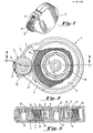
- Figures 1, 2, and 3 show one embodiment of the two-reel tape dispenser of the present invention.
- the perspective view of Figure 1 shows dispenser 1 without tape.
- the plan view of Figure 2 shows these components in greater detail.
- Transfer adhesive tape 7 is unwound from the supply reel and wound onto the take-up reel, as shown.
- the transfer tape preferably includes a backing material to which a transfer adhesive is attached. The adhesive and backing are not separately illustrated. The tape is wound around. core 19.
- Slots 8 in take-up reel 5 facilitate the attachment of tape 7 to the take-up reel.
- a loop of tape is fastened around the slots, as shown.
- the take-up reel rotates, a plurality of layers of spent backing are deposited onto the reel.
- the take-up reel has gear teeth across its entire width.
- the tape backing will be wound around most of the width of these teeth, the remainder of the width being used for geared engagement with the supply reel.
- the take-up reel and supply reel are mounted within a housing which includes top and bottom portions 9 and 11. As shown most clearly in Figure 3, bottom portion 11 defines bearing 13 for the supply reel.
- Supply reel 3 also includes a plurality of resilient teeth 15 having heads 17. The teeth and heads are disposed at an angle such that the heads abut the interior surface of core 19 of the roll of tape. Because of the angle of inclination of the teeth and their heads, the heads continually press firmly against the interior surface of the core, and oppose, by friction, the relative rotation of the supply reel and the roll of tape. However, because the roll of tape and the supply reel are engaged by friction only, relative rotation is possible, when the tape is unwound from the supply reel sufficiently rapidly.
- the teeth thus comprise a slip clutch for the supply reel and core.
- the slip clutch holds the roll of tape stationary with respect to the supply reel, except when the take-up reel is demanding additional tape.
- Bottom portion 11 of the housing also defines bearing 21 around which take-up reel 5 can rotate.
- Top portion 9 of the housing includes plugs 23, which fit within bearings 13 and 21. Retaining ring 33 prevents the core from slipping away from the supply reel, especially when the core is rotating relative to the reel.
- the user grasps the housing of the dispenser, and holds it so that the take-up roller presses firmly against the surface to which adhesive is to be transferred. If the dispenser shown in Figure 2 is moved downward, in the plane of the paper, the takeup reel will rotate in the direction indicated by arrow 25, causing the supply reel to rotate in the direction given by arrow 27.
- the rotating take-up reel also acts as an applicator roller, depositing the transfer adhesive onto the surface.
- Figures 4 and 5 illustrate another means by which the take-up reel and supply reel can be engaged for rotation.
- the gear drive and the slip clutch are replaced by one element, namely an O-ring or gasket 48.
- the dispenser includes supply reel 42 and take-up reel 44, with tape 46 being unwound from the supply reel and onto the take-up reel.
- O-ring 48 is disposed tightly around the supply reel, and is positioned to contact side portion 76 of the take-up reel.
- the O-ring is fastened around the supply reel with sufficient tightness such that rotation of the O-ring, due to friction with the take-up reel, causes rotation of the supply reel.
- the take-up reel rotates in the direction indicated by arrow 54
- the supply reel rotates in the direction of arrow 56.
- the embodiment of Figures 4 and 5 includes means for preventing any slippage between core 58 and supply reel 42.
- the supply reel has a plurality of projections 60 which mate with indentations 62 in the core. Note that, in the embodiment shown, there are nine indentations in the core, but only four projections on the supply reel. In general, the number of projections and indentations need not be the same, provided that there is at least one projection which mates with a corresponding indentation. Figures 4 and 5 thus illustrate a case where not all of the indentations have a corresponding projection.
- the supply reel may have a full complement of projections, or it may have a smaller number, so as to accommodate different styles of cores.
- Take-up reel 44 includes slot 64 through which tape 46 can be threaded.
- the dispenser is disposed in a housing which includes top portion 66 and bottom portion 68.
- Bottom portion 68 defines bearing 70 around which supply reel 42 rotates, and bearing 72, around which take-up reel 44 rotates.
- Top portion 66 includes plugs 74 which fit into the bearings.
- the O-ring 48 engages side portion 76 of take-up reel 44. The tape is not wound around this side portion.
- the dispenser of Figures 4 and 5 operates in a manner similar to the dispenser shown in Figures 1-3. That is, the dispenser is held such that the take-up reel presses firmly against the working surface, and the dispenser is moved along that surface. The take-up reel rotates, depositing the transfer adhesive onto the surface, and pulling additional tape from the supply reel. Due to the difference between the diameter of ring 50 of the supply reel, and that of the take-up reel, the take-up reel tends to pull tape from the supply reel, without developing slack in the tape. To the extent that the take-up reel requires more tape than is allowed by the normal rotation of the supply reel, the two reels slide relative to each other, overcoming the frictional resistance of the O-ring.
- Figure 6 shows an alternative embodiment of the invention, wherein the supply reel 90 and take-up reel 92 are connected through a modified gear drive.
- the modified gear drive allows take-up reel 92 to drive supply reel 90 in one direction only.
- the take-up reel rotates in the direction of arrow 94
- the supply reel rotates in the direction of arrow 96. But if one attempts to rotate the take-up reel in the direction opposite to that of arrow 94, the reels will lock, and the supply reel does not move by any significant amount.
- Figures 7a and 7b illustrate the construction of the modified gear drive in more detail.
- Gear 98 is connected to take-up reel 92, and gear 100 is connected to supply reel 90.
- the teeth of gear 98 are modified as will be described below.
- the teeth of gear 100 are not modified, and preferably have the shape of a standard involute curve.
- the sides of the teeth of gear 98 originally have the same shape as those of the teeth of gear 100, i.e. the shape of an involute curve. Every other tooth of gear 98 is partially cut away to form a step, such as step 102. The corresponding sides of the remaining teeth, i.e. the unstepped teeth, are cut away in their entireties. The fact that the entire side of tooth 104 has been cut away is apparent from a visual comparison of tooth 104 of gear 98 with tooth 106 of gear 100. Tooth 106 is wider than tooth 104.
- Each step 102 is formed by cutting the tooth along a line which begins at the midpoint of the uncut top land 108 of the tooth, and which line continues along a path generally parallel to the side of the uncut tooth.
- the line of cutting has the shape of an involute curve.
- the position of the step is chosen such that the ratio of the radial distance between the step and the top land, to the entire depth of the tooth (i.e. the radial distance between the top lands 108 and bottom lands 110), is in the range of about .33-.75.
- the fraction .667 two-thirds has been found to work especially well, and is what is shown in the drawings.
- the teeth which are not formed with steps are cut away along a line of cutting which also begins at the midpoint of the uncut top land, and which continues along a path which is generally parallel to the side of the uncut tooth, until the tooth is cut virtually down to the bottom land 110 between the teeth.
- the cutting is done on the side which corresponds to the side on which steps are formed on the other teeth.
- side 112 which has been cut away. Again, since the cutting is done along a line generally parallel to the uncut side of the tooth, side 112 still has the shape of an involute curve.
- gear 98 rotates in the direction of arrow 114
- gear 98 drives gear 100 in the usual manner
- gear 100 rotates in the direction of arrow 116.
- the steps and cut-away portions of the teeth of gear 98 have no effect when the gears rotate in this direction because the points of engagement of the gear teeth are on the unmodified sides of the teeth.
- step 120 of tooth 122 of gear 98, becomes stuck on top land 124 of tooth 126 of gear 100.
- the locking is also a consequence of the fact that the unstepped teeth of gear 98 have been cut away. For example, because the side of tooth 130 has been cut away, side 128 engages tooth 132 somewhat later than would be the case if the side of tooth 130 had not been cut away.
- This delayed engagement causes step 120 to become stuck on the top land of the opposite tooth.
- gear 98 will drive gear 100 in one direction only. It is also apparent, from Figures 7a and 7b, that gear 100 can drive gear 98 in either direction. It can also be shown that if gear 100 were modified in the same manner as gear 98, gear 100 would be able to drive gear 98 in only one direction. However, as used in the tape dispenser described herein, gear 100 is not the driving gear, so it is unnecessary to modify gear 100.
- the take-up reel can rotate the supply reel in only one direction. Thus, if the user accidentally tries to move the take-up reel in the wrong direction, the reels will lock, and neither reel will move by any significant amount. Thus, the invention reduces the likelihood that the tape will unwind and form unwanted loops.
- Figures 8-10 show two more embodiments having means for preventing movement of the reels in the undesired direction.
- take-up reel 152 drives supply reel 150 through O-ring 154.
- One-way pin 156 is held within wedge-shaped restriction 158.
- the restriction is connected to supply reel 150 and mounted to rotate around spindle 160.
- take- up reel 152 rotates in the direction of arrow 162
- supply reel rotates In the direction of arrow 164.
- restriction 158 simply carries the pin with it.
- the structure of Figure 8 effectively prevents the user from rotating the take-up reel in the wrong direction, and prevents undesired unwinding of the tape.
- FIGs 9 and 10 there is shown a similar structure for use with gear-driven reels.
- Take-up reel 170 drives supply reel 172 through a gear drive.
- This gear drive can be of the type shown in Figures 1-3, or the modified type of Figures 6 and 7.
- Pinion gear 174 engages the gear of supply reel 172, and is held within restriction 176.
- Restriction 176 is wedge-shaped, like restriction 158. Retaining protrusion 178 prevents the pinion gear from falling out of restriction 176.
- the dispenser may be modified further, without departing from the general concept of the invention.
- the structure of the gaskets or gears can be modified, as can the exact location of those items.
- the gasket in Figures 4 and 5 could be located on the take-up reel instead of the supply reel.
- the slip clutch can be replaced with a clutch of a different structure.
- the pinion gear or the one-way pin can be connected to the take-up reel, instead of the supply reel, although the embodiment shown is preferred.
- the one-way pin, instead of the pinion gear could be used in the embodiment in which the reels are engaged by gears.
Landscapes
- Adhesive Tape Dispensing Devices (AREA)
- Storage Of Web-Like Or Filamentary Materials (AREA)
- Storing, Repeated Paying-Out, And Re-Storing Of Elongated Articles (AREA)
- Adhesive Tapes (AREA)
Applications Claiming Priority (2)
| Application Number | Priority Date | Filing Date | Title |
|---|---|---|---|
| US253118 | 1988-10-04 | ||
| US07/253,118 US4891090A (en) | 1988-10-04 | 1988-10-04 | Two-reel dispenser for a transfer adhesive |
Publications (1)
| Publication Number | Publication Date |
|---|---|
| EP0362697A1 true EP0362697A1 (de) | 1990-04-11 |
Family
ID=22958943
Family Applications (1)
| Application Number | Title | Priority Date | Filing Date |
|---|---|---|---|
| EP89117973A Withdrawn EP0362697A1 (de) | 1988-10-04 | 1989-09-28 | Zweispulenspender für ein Klebeband |
Country Status (3)
| Country | Link |
|---|---|
| US (1) | US4891090A (de) |
| EP (1) | EP0362697A1 (de) |
| JP (1) | JPH02151679A (de) |
Cited By (7)
| Publication number | Priority date | Publication date | Assignee | Title |
|---|---|---|---|---|
| FR2699905A1 (fr) * | 1992-12-28 | 1994-07-01 | Toyo Kagaku Kk | Dispositif de transfert automatique d'un adhésif. |
| EP0680914A1 (de) * | 1994-05-02 | 1995-11-08 | CZEWO PLAST KUNSTSTOFFTECHNIK GmbH | Vorrichtung zur Abgabe von Auftrags-Material |
| WO1997046475A1 (de) * | 1996-06-05 | 1997-12-11 | Kores Holding Zug Ag | Vorrichtung zum übertragen eines auf einem folienband einseitig vorliegenden films |
| WO1999038788A1 (de) * | 1998-01-30 | 1999-08-05 | Henkel Kommanditgesellschaft Auf Aktien | Haftmaterialspender |
| EP1055628A1 (de) * | 1999-05-28 | 2000-11-29 | Tombow Pencil Co., Ltd. | Wellenkonstruktion eines Beschichtungwerkzeugs |
| WO2001062645A1 (en) * | 2000-02-25 | 2001-08-30 | Bic Deutschland Gmbh & Co. | A hand-held device for transferring a film onto a substrate, comprising a concealable application member |
| EP1898276A1 (de) * | 2006-09-06 | 2008-03-12 | Chopard Manufacture SA | Unidirektionales Getriebe, insbesondere für Uhren |
Families Citing this family (31)
| Publication number | Priority date | Publication date | Assignee | Title |
|---|---|---|---|---|
| US5316613A (en) * | 1991-09-06 | 1994-05-31 | Minnesota Mining And Manufacturing Company | Definite length transfer adhesive dispenser |
| GB2275042B (en) | 1993-02-10 | 1995-10-25 | Gillette Co | Correction tape dispenser |
| JP2869855B2 (ja) * | 1995-03-28 | 1999-03-10 | 株式会社トンボ鉛筆 | 字消し具 |
| US6808565B1 (en) | 1995-10-06 | 2004-10-26 | Seed Rubber Co., Ltd. | Clutch mechanism of coat film transfer tool and coat film transfer tool |
| US5795435A (en) * | 1995-11-08 | 1998-08-18 | Waters, Jr.; Jesse Walter | Transfer tape applicator system |
| DE19606626C2 (de) * | 1996-02-22 | 1998-05-20 | Pritt Produktionsgesellschaft | Reibungsbremse für einen Dispenser zur drehmomentbegrenzenden Kraftübertragung zwischen einem Spulenkern einer Spule zum Auf- oder Abwickeln eines Bandes und einer Drehaufnahme |
| US5851347A (en) * | 1997-04-02 | 1998-12-22 | Martin Yale Industries, Inc. | Stamp affixer apparatus and method |
| US5851348A (en) * | 1997-04-28 | 1998-12-22 | Barbara Thomas Enterprises, Inc. | Dispenser for tags, labels, indexing tabs and the like |
| US6098690A (en) * | 1998-06-26 | 2000-08-08 | Robichaud; Andre M. | Tape dispensing system with automatic backing removal |
| CA2372950A1 (en) | 1999-05-05 | 2000-11-09 | Xyron, Inc. | Adhesive transfer apparatus with take-up roll and a removable cartridge for a master processing apparatus |
| US6576080B1 (en) * | 1999-10-20 | 2003-06-10 | Xyron, Inc. | Adhesive transfer device |
| DE60012924T2 (de) * | 2000-09-08 | 2005-01-13 | SOCIéTé BIC | Rutschkupplung zur drehmomentbegrenzenden Kraftübertragung, insbesondere für ein Handgerät zum Übertragen eines Filmes von einem Trägerband auf ein Substrat |
| US6527028B2 (en) | 2000-10-02 | 2003-03-04 | Xyron, Inc. | Substrate processing apparatus having pressed together supply rolls |
| NL1017933C2 (nl) * | 2001-04-24 | 2002-10-25 | Innoseal Systems Internat B V | Inrichting voor het afgeven van kleefband. |
| AU2002317551B2 (en) | 2001-07-20 | 2006-10-19 | Xyron, Inc. | Substrate processing apparatus |
| JP2003095523A (ja) * | 2001-09-27 | 2003-04-03 | Saitoo:Kk | 粘着テープ等の繰り出し装置及び該繰り出し装置を備えた便座シート収納キャビネット |
| US7204287B2 (en) * | 2003-01-23 | 2007-04-17 | Xyron, Inc. | Transfer devices |
| DE20311532U1 (de) * | 2003-07-26 | 2004-11-25 | Planatol Klebetechnik Gmbh | Klebemittel |
| US6997229B2 (en) * | 2003-09-16 | 2006-02-14 | Sanford, L.P. | Rotatable applicator tip for a corrective tape dispenser |
| US20050056375A1 (en) * | 2003-09-16 | 2005-03-17 | Sanford, L.P. | Applicator tip for a corrective tape dispenser |
| US7520952B1 (en) * | 2004-10-15 | 2009-04-21 | Innovatime Dreams Corp. | Adhesive lifting mechanism |
| US8012291B2 (en) * | 2006-12-11 | 2011-09-06 | The Boeing Company | Backing film removal system and method for fiber placement machine |
| US8397784B2 (en) | 2010-08-31 | 2013-03-19 | Sanford, L.P. | Correction tape dispenser with variable clutch mechanism |
| DK177129B1 (da) | 2010-09-06 | 2011-12-19 | Barry Daniel | En håndholdt tildækningsanordning |
| US8746313B2 (en) | 2010-12-29 | 2014-06-10 | Sanford, L.P. | Correction tape re-tensioning mechanism and correction tape dispenser comprising same |
| US8578999B2 (en) | 2010-12-29 | 2013-11-12 | Sanford, L.P. | Variable clutch mechanism and correction tape dispenser with variable clutch mechanism |
| US8746316B2 (en) | 2011-12-30 | 2014-06-10 | Sanford, L.P. | Variable clutch mechanism and correction tape dispenser with variable clutch mechanism |
| ES2680586T3 (es) * | 2013-03-15 | 2018-09-10 | Elc Management Llc | Método para aplicar pestañas postizas |
| JP2015202593A (ja) * | 2014-04-11 | 2015-11-16 | セイコーエプソン株式会社 | 造形材料供給機構、及び造形装置 |
| US10046937B2 (en) * | 2016-07-28 | 2018-08-14 | John L. Davidson | Painters masking tape tool |
| JP7665179B2 (ja) * | 2021-01-05 | 2025-04-21 | プラス株式会社 | 転写具 |
Citations (4)
| Publication number | Priority date | Publication date | Assignee | Title |
|---|---|---|---|---|
| US4718971A (en) * | 1986-10-09 | 1988-01-12 | Moore Push-Pin Company | Dispenser for a transfer adhesive |
| DE3736357C1 (de) * | 1987-10-27 | 1988-11-24 | Pelikan Ag | Handgeraet zum UEbertragen eines Filmes von einer Traegerfolie auf ein Substrat |
| EP0292861A1 (de) * | 1987-05-28 | 1988-11-30 | Doro Tape Ehlis Kg | Abrollgerät für Transferband |
| DD268038A1 (de) * | 1987-12-14 | 1989-05-17 | Ruhla Uhren Veb K | Zahnradgetriebe |
Family Cites Families (26)
| Publication number | Priority date | Publication date | Assignee | Title |
|---|---|---|---|---|
| US474629A (en) * | 1892-05-10 | Device for | ||
| USRE25056E (en) | 1961-10-17 | fritzinger | ||
| US25056A (en) * | 1859-08-09 | Machine foe | ||
| US466923A (en) * | 1892-01-12 | Mechanical movement | ||
| US2399925A (en) * | 1943-12-20 | 1946-05-07 | Gen Electric | Unidirectional gear drive |
| US2436231A (en) * | 1945-10-20 | 1948-02-17 | R W Cramer Company Inc | Self-starting synchronous motor |
| US3274038A (en) * | 1963-01-14 | 1966-09-20 | Andrew B Karn | Dispensing device |
| DE1255023B (de) * | 1964-04-10 | 1967-11-23 | Hansjoerg Rothenberger | Handgeraet zum Aufbringen eines Selbstklebebandes auf eine Unterlage |
| US3339797A (en) * | 1966-04-04 | 1967-09-05 | Kermit B Knutson | Label dispensers |
| US3509000A (en) * | 1967-09-19 | 1970-04-28 | Walter P Brown | Hand tool for applying rubber tape |
| US3839127A (en) * | 1973-06-01 | 1974-10-01 | Minnesota Mining & Mfg | Adhesive applicator |
| US3902956A (en) * | 1973-12-06 | 1975-09-02 | Minnesota Mining & Mfg | Pressure-sensitive tape applicating system |
| US3969181A (en) * | 1974-06-03 | 1976-07-13 | Minnesota Mining And Manufacturing Company | Transfer adhesive dispensing device |
| US4041794A (en) * | 1975-10-28 | 1977-08-16 | Ebauches S.A. | Mechanism of transmission |
| JPS6011270B2 (ja) * | 1976-03-03 | 1985-03-25 | リコー時計株式会社 | 歯車列における逆伝達防止機構 |
| US4051744A (en) * | 1976-10-15 | 1977-10-04 | Kabushiki Kaisha Seikosha | Gear mechanism for preventing reverse rotation |
| US4151039A (en) * | 1978-05-30 | 1979-04-24 | Lash Donald W | Double adhesive tape dispenser |
| US4200000A (en) * | 1978-10-04 | 1980-04-29 | Societe Suisse Pour L'industrie Horlogere Management Services S.A. | Gear train |
| US4223528A (en) * | 1978-10-31 | 1980-09-23 | Societe Suisse Pour L'industrie Horlogere Management Services, S.A. | Unidirectional gear transmission |
| US4207777A (en) * | 1978-11-07 | 1980-06-17 | Societe Suisse pour l'Industrie Horlogere Mangagement Services S.A. | One way gear train |
| FR2450982A1 (fr) * | 1979-03-08 | 1980-10-03 | Suisse Horlogerie | Engrenage a transmission de couple a sens unique, notamment pour montre |
| US4336097A (en) * | 1980-10-23 | 1982-06-22 | Minnesota Mining And Manufacturing Company | Dispenser for liner-wound tape |
| USD280738S (en) | 1982-10-05 | 1985-09-24 | Comet S.A.R.A. Societa Autoadesivi Resin E Affine S.P.A. | Adhesive tape applicator |
| US4576311A (en) * | 1983-08-30 | 1986-03-18 | Horton Stuart L | Tab dispenser with odor applicator |
| US4574030A (en) * | 1984-01-16 | 1986-03-04 | Pilcher Henry D | Apparatus for dispensing tape having a protective backing |
| US4653340A (en) * | 1986-03-03 | 1987-03-31 | Pitney Bowes Inc. | Beveled spur gear |
-
1988
- 1988-10-04 US US07/253,118 patent/US4891090A/en not_active Expired - Fee Related
-
1989
- 1989-09-28 JP JP1255069A patent/JPH02151679A/ja active Pending
- 1989-09-28 EP EP89117973A patent/EP0362697A1/de not_active Withdrawn
Patent Citations (4)
| Publication number | Priority date | Publication date | Assignee | Title |
|---|---|---|---|---|
| US4718971A (en) * | 1986-10-09 | 1988-01-12 | Moore Push-Pin Company | Dispenser for a transfer adhesive |
| EP0292861A1 (de) * | 1987-05-28 | 1988-11-30 | Doro Tape Ehlis Kg | Abrollgerät für Transferband |
| DE3736357C1 (de) * | 1987-10-27 | 1988-11-24 | Pelikan Ag | Handgeraet zum UEbertragen eines Filmes von einer Traegerfolie auf ein Substrat |
| DD268038A1 (de) * | 1987-12-14 | 1989-05-17 | Ruhla Uhren Veb K | Zahnradgetriebe |
Cited By (9)
| Publication number | Priority date | Publication date | Assignee | Title |
|---|---|---|---|---|
| FR2699905A1 (fr) * | 1992-12-28 | 1994-07-01 | Toyo Kagaku Kk | Dispositif de transfert automatique d'un adhésif. |
| EP0680914A1 (de) * | 1994-05-02 | 1995-11-08 | CZEWO PLAST KUNSTSTOFFTECHNIK GmbH | Vorrichtung zur Abgabe von Auftrags-Material |
| US5770007A (en) * | 1994-05-02 | 1998-06-23 | Czewo Plast Kunststoffechnik Gmbh | Device for dispensing transfer material |
| WO1997046475A1 (de) * | 1996-06-05 | 1997-12-11 | Kores Holding Zug Ag | Vorrichtung zum übertragen eines auf einem folienband einseitig vorliegenden films |
| WO1999038788A1 (de) * | 1998-01-30 | 1999-08-05 | Henkel Kommanditgesellschaft Auf Aktien | Haftmaterialspender |
| EP1055628A1 (de) * | 1999-05-28 | 2000-11-29 | Tombow Pencil Co., Ltd. | Wellenkonstruktion eines Beschichtungwerkzeugs |
| US6379461B1 (en) | 1999-05-28 | 2002-04-30 | Tombow Pencil Co., Ltd. | Coating tool |
| WO2001062645A1 (en) * | 2000-02-25 | 2001-08-30 | Bic Deutschland Gmbh & Co. | A hand-held device for transferring a film onto a substrate, comprising a concealable application member |
| EP1898276A1 (de) * | 2006-09-06 | 2008-03-12 | Chopard Manufacture SA | Unidirektionales Getriebe, insbesondere für Uhren |
Also Published As
| Publication number | Publication date |
|---|---|
| JPH02151679A (ja) | 1990-06-11 |
| US4891090A (en) | 1990-01-02 |
Similar Documents
| Publication | Publication Date | Title |
|---|---|---|
| US4891090A (en) | Two-reel dispenser for a transfer adhesive | |
| US4718971A (en) | Dispenser for a transfer adhesive | |
| US5472560A (en) | Tape dispenser | |
| US5490898A (en) | Coating film transfer tool | |
| US4826562A (en) | Device for unwinding transfer tape from a roll | |
| KR100493473B1 (ko) | 캐리어 테입으로부터 바탕재로의 필름 이전용 수동 장치 | |
| JP3296265B2 (ja) | 塗膜転写具のクラッチ機構および塗膜転写具 | |
| US5125589A (en) | Tape dispenser with controlled-friction unwind | |
| CA2164757A1 (en) | Tape cartridge for coating film transfer tool and coating film transfer tool | |
| US20020088554A1 (en) | Manual device for transferring a film from a backing strip to a substrate | |
| US6453968B1 (en) | Dispensing device for double-face adhesive tape | |
| US4350453A (en) | Cartridge for correction media or tacky tape with a wrap spring | |
| CA2091996C (en) | Device for transferring film | |
| CA2389838C (en) | Manual device with a return stop for transferring a film from a backing strip onto a substrate | |
| EP0717000A2 (de) | Bandkassette für ein Übertragungswerkzeug für Beschichtungsfilm und ein Übertragungswerkzeug für Beschichtungsfilm | |
| JPH02228383A (ja) | 粘着フィルムの貼着装置 | |
| CA2430463A1 (en) | Hand-held adhesive tape dispenser | |
| AU2002236680B2 (en) | Viscous clutch for a correction tape reel assembly | |
| JP2004114589A (ja) | リボンカセット | |
| JPH05178525A (ja) | 塗膜転写具 | |
| AU2002236680A1 (en) | Viscous clutch for a correction tape reel assembly | |
| EP0075664B1 (de) | Farbbandkassette mit einer Vorrichtung zum Zurückhalten der Aufwickelspule | |
| JPH0425154B2 (de) | ||
| US4772143A (en) | Reloadable ribbon cartridge | |
| ITTO990190A1 (it) | Dispositivo a nastro di trasferimento di adesivo |
Legal Events
| Date | Code | Title | Description |
|---|---|---|---|
| PUAI | Public reference made under article 153(3) epc to a published international application that has entered the european phase |
Free format text: ORIGINAL CODE: 0009012 |
|
| AK | Designated contracting states |
Kind code of ref document: A1 Designated state(s): AT BE CH DE ES FR GB GR IT LI LU NL SE |
|
| 17P | Request for examination filed |
Effective date: 19901010 |
|
| STAA | Information on the status of an ep patent application or granted ep patent |
Free format text: STATUS: THE APPLICATION HAS BEEN WITHDRAWN |
|
| 18W | Application withdrawn |
Withdrawal date: 19911111 |
|
| R18W | Application withdrawn (corrected) |
Effective date: 19911111 |