EP0362748A1 - Reifenwulst - Google Patents
Reifenwulst Download PDFInfo
- Publication number
- EP0362748A1 EP0362748A1 EP89118187A EP89118187A EP0362748A1 EP 0362748 A1 EP0362748 A1 EP 0362748A1 EP 89118187 A EP89118187 A EP 89118187A EP 89118187 A EP89118187 A EP 89118187A EP 0362748 A1 EP0362748 A1 EP 0362748A1
- Authority
- EP
- European Patent Office
- Prior art keywords
- bead
- seat
- rim
- axially
- tire
- Prior art date
- Legal status (The legal status is an assumption and is not a legal conclusion. Google has not performed a legal analysis and makes no representation as to the accuracy of the status listed.)
- Granted
Links
- 239000011324 bead Substances 0.000 title claims abstract description 51
- 230000002441 reversible effect Effects 0.000 claims description 5
- 238000000465 moulding Methods 0.000 description 3
- 239000006185 dispersion Substances 0.000 description 2
- 238000004519 manufacturing process Methods 0.000 description 2
- 238000004073 vulcanization Methods 0.000 description 2
- 230000006835 compression Effects 0.000 description 1
- 238000007906 compression Methods 0.000 description 1
- 239000000463 material Substances 0.000 description 1
- 230000036961 partial effect Effects 0.000 description 1
- 230000002093 peripheral effect Effects 0.000 description 1
- 230000002829 reductive effect Effects 0.000 description 1
- 230000000284 resting effect Effects 0.000 description 1
- 238000005096 rolling process Methods 0.000 description 1
- 239000007787 solid Substances 0.000 description 1
- 238000007711 solidification Methods 0.000 description 1
- 230000008023 solidification Effects 0.000 description 1
- 230000003068 static effect Effects 0.000 description 1
Images
Classifications
-
- B—PERFORMING OPERATIONS; TRANSPORTING
- B60—VEHICLES IN GENERAL
- B60C—VEHICLE TYRES; TYRE INFLATION; TYRE CHANGING; CONNECTING VALVES TO INFLATABLE ELASTIC BODIES IN GENERAL; DEVICES OR ARRANGEMENTS RELATED TO TYRES
- B60C15/00—Tyre beads, e.g. ply turn-up or overlap
- B60C15/02—Seating or securing beads on rims
- B60C15/024—Bead contour, e.g. lips, grooves, or ribs
-
- B—PERFORMING OPERATIONS; TRANSPORTING
- B60—VEHICLES IN GENERAL
- B60C—VEHICLE TYRES; TYRE INFLATION; TYRE CHANGING; CONNECTING VALVES TO INFLATABLE ELASTIC BODIES IN GENERAL; DEVICES OR ARRANGEMENTS RELATED TO TYRES
- B60C15/00—Tyre beads, e.g. ply turn-up or overlap
- B60C15/02—Seating or securing beads on rims
- B60C15/0206—Seating or securing beads on rims using inside rim bead seating, i.e. the bead being seated at a radially inner side of the rim
Definitions
- the present invention relates to the beads of those of the tires which bear radially from the inside on the rim, called reverse hooked tires.
- the rims designed to receive such tires comprise, on each side, a seat, usually inclined slightly relative to the axis of the rim.
- the seat is extended axially towards the outside by a flange substantially perpendicular to the axis and extending radially towards the inside of the rim.
- the tire In order to ensure correct positioning of the tire on the rim, guaranteeing good static and dynamic balancing, the tire must be in regular support both on the seat and against the rim. In other words, the rim-pneumatic contact pressure must be constant circumferentially.
- the bead of tires with reverse latching generally comprises a large volume of rubber, which results in a great dispersion of the positioning of the bead wire. If we add to this the influence of the dispersions caused by the manufacturing tolerances of the rims and rods, as well as the molding tolerances of the bead, it follows that, in the mounting position, the thickness ratio of rubber included between the bead wire and the face of the bead intended to be pressed on the rim, said thickness being divided by the length of the space available between the bead wire considered to be ideally centered and the surface of the rim varies in significant proportions. However, this ratio determines the tightening of the bead on the rim. The variations of this ratio are very often more important than the tolerances which one would like to be able to respect for this tightening.
- the rod is offset from the rim and / or is not arranged flat, and / or is arranged non-parallel to the flange.
- the objective of the present invention is therefore to position the bead on the rim as precisely as possible.
- the tire according to the invention of the reverse latching type, comprising a tread, two sidewalls each ending in a bead, each bead comprising at least one bead, said bead resting on the seat of the rim, said seat being limited on the axially outer side by a rim flange, is characterized in that, in the mounting position and on the axially outer side to a plane perpendicular to the axis of rotation and tangent to the bead wire on the axially inner side thereof, the area corresponding to effective contact of the bead on the seat is less than the area of said seat between said plane and said flange.
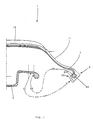
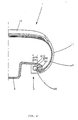
- the tire 1 with reverse latching an axial half of which can be seen in FIGS. 1 and 2, comprises a tread 10, two sidewalls 11 and two beads 2.
- the bead 2 of this type of tire 1 is supported on the seat 31 of the rim 3 by a contact face 21 which is, in the mounting position, disposed radially outside the bead wire 20. It bears axially on the rim 32 of the rim, located axially on the outside of the bead wire 20.
- the position in which the vulcanization is carried out is usually that visible in FIG. 1, where it can be seen that the bead 2 is, relative to the mounting position visible in FIG. 2, tilted by a large angle (approximately 130 °).
- This difference aggravates the influence of the manufacturing tolerances of the bead wire 20 and of the rim 3 and of the positioning error of the bead wire 20 inside the bead 2 on the tightening of the bead 2 on the rim 3.
- the bead 20 is stressed in compression, while in the tires hooked from outside the rim, the bead is stressed in traction. All this makes this tire 1 more sensitive to inaccuracies in the positioning of the bead 20.
- Each bead 2 bears on the rim 3 by a contact face 21, the radial projection of which (tire considered in the mounting position) on the rim 3 defines the seat 31. It also rests on the flange 32 of the rim 3 by a surface 22 substantially perpendicular to the contact face 21.
- the contact pressure of the bead 2 on the seat 31 seems to be an important parameter for the good performance of the tire 1. It must be sufficient to ensure correct centering of the tire 1 relative to the rim 3, and not excessive to ensure mounting. correct, rod 20 well parallel to the flange 32 playing a role of the mechanical stop.
- the surface 210 corresponding to an effective contact of the bead 2 on the seat 31 is less than the surface 310 of said seat 31 between said tangent plane and said flange 32. It is in fact this zone which has a decisive influence on the tightening of the bead 2 on the rim 3.
- this reduction in effective contact is obtained by placing at least one continuous peripheral groove on the contact face 21.
- This can therefore be defined as a rate of notching, a concept comparable to that used for band sculptures. of rolling.
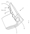
- the zone 23 of the bead 2 corresponding to the intersection of the seat 31 and the flange 32 of the rim has a plurality of recesses 230 distributed over the circumference, and separated by bosses 231, said recesses 230 extending up to the carcass 4 at the place where it surrounds the bead wire 20.
- the section of the bead n is therefore not identical on any circumference. This appears clearly in FIG. 3.
- the surface corresponds to an effective contact of the bead 2 on the seat 31 is constituted by a bearing of circumferentially constant width, to which is added a bearing at the end of each boss 231
- the rate of notching is between 30% and 70%, considering the part of the face 21 axially external to the plane tangent to the rod 20 on the axially inner side of that -this.
Landscapes
- Engineering & Computer Science (AREA)
- Mechanical Engineering (AREA)
- Tires In General (AREA)
- Tyre Moulding (AREA)
Priority Applications (1)
| Application Number | Priority Date | Filing Date | Title |
|---|---|---|---|
| AT89118187T ATE80093T1 (de) | 1988-10-05 | 1989-09-30 | Reifenwulst. |
Applications Claiming Priority (2)
| Application Number | Priority Date | Filing Date | Title |
|---|---|---|---|
| FR8813148A FR2637230B1 (fr) | 1988-10-05 | 1988-10-05 | Bourrelet de pneumatique |
| FR8813148 | 1988-10-05 |
Publications (2)
| Publication Number | Publication Date |
|---|---|
| EP0362748A1 true EP0362748A1 (de) | 1990-04-11 |
| EP0362748B1 EP0362748B1 (de) | 1992-09-02 |
Family
ID=9370769
Family Applications (1)
| Application Number | Title | Priority Date | Filing Date |
|---|---|---|---|
| EP89118187A Expired - Lifetime EP0362748B1 (de) | 1988-10-05 | 1989-09-30 | Reifenwulst |
Country Status (6)
| Country | Link |
|---|---|
| US (1) | US5125446A (de) |
| EP (1) | EP0362748B1 (de) |
| AT (1) | ATE80093T1 (de) |
| DE (1) | DE68902719T2 (de) |
| ES (1) | ES2034547T3 (de) |
| FR (1) | FR2637230B1 (de) |
Families Citing this family (1)
| Publication number | Priority date | Publication date | Assignee | Title |
|---|---|---|---|---|
| US6845798B1 (en) | 1999-09-30 | 2005-01-25 | The Goodyear Tire & Rubber Co. | Locked bead construction |
Citations (4)
| Publication number | Priority date | Publication date | Assignee | Title |
|---|---|---|---|---|
| EP0152567A2 (de) * | 1984-02-15 | 1985-08-28 | Continental Aktiengesellschaft | Fahrzeugrad |
| EP0153295A2 (de) * | 1984-02-22 | 1985-08-28 | Semperit Reifen Aktiengesellschaft | Luftbereiftes Fahrzeugrad |
| DE3605803A1 (de) * | 1986-02-22 | 1987-01-02 | Daimler Benz Ag | Fahrzeugrad |
| EP0212333A2 (de) * | 1985-08-17 | 1987-03-04 | Continental Aktiengesellschaft | Fahrzeugrad |
Family Cites Families (5)
| Publication number | Priority date | Publication date | Assignee | Title |
|---|---|---|---|---|
| US1915963A (en) * | 1930-09-30 | 1933-06-27 | Firestone Tire & Rubber Co | Method of tire construction |
| DE893164C (de) * | 1943-09-06 | 1953-10-12 | Continental Gummi Werke Ag | Ohne Luftschlauch benutzbarer Fahrzeugluftreifen |
| JPS59149802A (ja) * | 1983-02-12 | 1984-08-27 | Sumitomo Rubber Ind Ltd | 耐久性の改良された重車両用タイヤ |
| DE3804505A1 (de) * | 1988-02-13 | 1989-08-24 | Continental Ag | Luftbereiftes fahrzeugrad |
| FR2632571A1 (fr) * | 1988-06-09 | 1989-12-15 | Michelin & Cie | Jante pour pneumatique a accrochage inverse |
-
1988
- 1988-10-05 FR FR8813148A patent/FR2637230B1/fr not_active Expired - Fee Related
-
1989
- 1989-09-30 AT AT89118187T patent/ATE80093T1/de not_active IP Right Cessation
- 1989-09-30 EP EP89118187A patent/EP0362748B1/de not_active Expired - Lifetime
- 1989-09-30 DE DE8989118187T patent/DE68902719T2/de not_active Expired - Fee Related
- 1989-09-30 ES ES198989118187T patent/ES2034547T3/es not_active Expired - Lifetime
-
1991
- 1991-02-21 US US07/657,939 patent/US5125446A/en not_active Expired - Fee Related
Patent Citations (4)
| Publication number | Priority date | Publication date | Assignee | Title |
|---|---|---|---|---|
| EP0152567A2 (de) * | 1984-02-15 | 1985-08-28 | Continental Aktiengesellschaft | Fahrzeugrad |
| EP0153295A2 (de) * | 1984-02-22 | 1985-08-28 | Semperit Reifen Aktiengesellschaft | Luftbereiftes Fahrzeugrad |
| EP0212333A2 (de) * | 1985-08-17 | 1987-03-04 | Continental Aktiengesellschaft | Fahrzeugrad |
| DE3605803A1 (de) * | 1986-02-22 | 1987-01-02 | Daimler Benz Ag | Fahrzeugrad |
Non-Patent Citations (1)
| Title |
|---|
| PATENT ABSTRACTS OF JAPAN, vol. 8, no. 280 (M-347)[1717], 21 décembre 1984, page 66 M 347; & JP-A-59 149 802 (SUMITOMO GOMU KOGYO K.K.) 27-08-1984 * |
Also Published As
| Publication number | Publication date |
|---|---|
| US5125446A (en) | 1992-06-30 |
| ATE80093T1 (de) | 1992-09-15 |
| DE68902719T2 (de) | 1993-03-18 |
| ES2034547T3 (es) | 1993-04-01 |
| DE68902719D1 (de) | 1992-10-08 |
| FR2637230B1 (fr) | 1991-05-03 |
| FR2637230A1 (fr) | 1990-04-06 |
| EP0362748B1 (de) | 1992-09-02 |
Similar Documents
| Publication | Publication Date | Title |
|---|---|---|
| EP0748287B1 (de) | Luftreifen mit verbesserter struktur der wülste und einheit von einer reifenfelge | |
| EP0796747B1 (de) | Notlaufring aus weichem Elastomermaterial für einen Reifen | |
| CA2324519A1 (fr) | Jante destinee a recevoir un anneau de soutien | |
| WO1992001577A1 (fr) | Ensemble roulant compose d'un pneumatique dont les bourrelets ont des bases tronconiques, d'une jante de montage a sieges plats, et d'adaptateurs annulaires en caoutchouc et adaptateur conçu pour cet ensemble | |
| FR2707923A1 (fr) | Dispositif de soutien d'une bande de roulement de pneumatique. | |
| EP0362748B1 (de) | Reifenwulst | |
| FR2698823A1 (fr) | Dispositif d'anneau perfectionné pour roulage à plat. | |
| EP0780218B1 (de) | Form mit steifem Kern für ringförmige Reifendecken, insbesondere zur Runderneuerung von Reifen | |
| EP0790141A1 (de) | Felge eines Speichenrades für schlauchlose Reifen und damit ausgerüstetes Speichenrad | |
| EP0226967B1 (de) | Sicherheitsvorrichtung für ein Notlaufrad | |
| FR2818585A1 (fr) | Ensemble d'une jante et d'un appui de soutien | |
| CA2126658C (fr) | Procede et dispositif d'assemblage d'une carcasse de pneumatique et d'une bande de roulement annulaire etiree par centrifugation | |
| EP0626279B1 (de) | Dichtungsstreifen zwischen Reifenwülste | |
| EP1153769B1 (de) | Notlaufvorrichtung für Fahrzeuge | |
| EP0835769B9 (de) | Stützvorrichtung für eine Reifenlauffläche | |
| EP0498214B1 (de) | Einheit Felge-Reifen, die eine Entwulstung vermeidet | |
| EP0254112B1 (de) | Ventil für Luftreifen ohne Schlauch; Befestigung des Ventilsgehäuses in der Felge | |
| FR2502551A1 (fr) | Jante de roue | |
| FR2755905A1 (fr) | Dispositif de roulage a plat pour vehicule automobile | |
| EP0764795A1 (de) | Ventilkolben für hydraulischen Dämpfer | |
| EP0345612B1 (de) | Radfelge für Reifen mit umschlingender Einklammerung | |
| FR2480454A1 (fr) | Dispositif pour la pose et la depose de verre de montre de forme | |
| EP1538007B1 (de) | Notlaufvorrichtung für Kraftfahrzeug und diese enthaltende Radeinheit | |
| FR3117154A1 (fr) | Systeme de fixation de plateforme aérodynamique pour une soufflante à aubes à calage variable | |
| FR2661372A1 (fr) | Pneumatique pour roue de train d'atterrissage d'avion. |
Legal Events
| Date | Code | Title | Description |
|---|---|---|---|
| PUAI | Public reference made under article 153(3) epc to a published international application that has entered the european phase |
Free format text: ORIGINAL CODE: 0009012 |
|
| 17P | Request for examination filed |
Effective date: 19891010 |
|
| AK | Designated contracting states |
Kind code of ref document: A1 Designated state(s): AT BE CH DE ES FR GB GR IT LI LU NL SE |
|
| 17Q | First examination report despatched |
Effective date: 19911125 |
|
| GRAA | (expected) grant |
Free format text: ORIGINAL CODE: 0009210 |
|
| AK | Designated contracting states |
Kind code of ref document: B1 Designated state(s): AT BE CH DE ES FR GB GR IT LI LU NL SE |
|
| PG25 | Lapsed in a contracting state [announced via postgrant information from national office to epo] |
Ref country code: SE Effective date: 19920902 Ref country code: NL Effective date: 19920902 Ref country code: GR Free format text: LAPSE BECAUSE OF FAILURE TO SUBMIT A TRANSLATION OF THE DESCRIPTION OR TO PAY THE FEE WITHIN THE PRESCRIBED TIME-LIMIT Effective date: 19920902 Ref country code: AT Effective date: 19920902 |
|
| REF | Corresponds to: |
Ref document number: 80093 Country of ref document: AT Date of ref document: 19920915 Kind code of ref document: T |
|
| PG25 | Lapsed in a contracting state [announced via postgrant information from national office to epo] |
Ref country code: LU Free format text: LAPSE BECAUSE OF NON-PAYMENT OF DUE FEES Effective date: 19920930 Ref country code: LI Effective date: 19920930 Ref country code: CH Effective date: 19920930 Ref country code: BE Effective date: 19920930 |
|
| REF | Corresponds to: |
Ref document number: 68902719 Country of ref document: DE Date of ref document: 19921008 |
|
| ITF | It: translation for a ep patent filed | ||
| GBT | Gb: translation of ep patent filed (gb section 77(6)(a)/1977) | ||
| NLV1 | Nl: lapsed or annulled due to failure to fulfill the requirements of art. 29p and 29m of the patents act | ||
| BERE | Be: lapsed |
Owner name: CIE GENERALE DES ETS MICHELIN-MICHELIN & CIE Effective date: 19920930 |
|
| REG | Reference to a national code |
Ref country code: ES Ref legal event code: FG2A Ref document number: 2034547 Country of ref document: ES Kind code of ref document: T3 |
|
| REG | Reference to a national code |
Ref country code: CH Ref legal event code: PL |
|
| PLBE | No opposition filed within time limit |
Free format text: ORIGINAL CODE: 0009261 |
|
| STAA | Information on the status of an ep patent application or granted ep patent |
Free format text: STATUS: NO OPPOSITION FILED WITHIN TIME LIMIT |
|
| 26N | No opposition filed | ||
| PGFP | Annual fee paid to national office [announced via postgrant information from national office to epo] |
Ref country code: ES Payment date: 19950809 Year of fee payment: 7 |
|
| PGFP | Annual fee paid to national office [announced via postgrant information from national office to epo] |
Ref country code: FR Payment date: 19950907 Year of fee payment: 7 |
|
| PGFP | Annual fee paid to national office [announced via postgrant information from national office to epo] |
Ref country code: GB Payment date: 19950921 Year of fee payment: 7 |
|
| PGFP | Annual fee paid to national office [announced via postgrant information from national office to epo] |
Ref country code: DE Payment date: 19960717 Year of fee payment: 8 |
|
| PG25 | Lapsed in a contracting state [announced via postgrant information from national office to epo] |
Ref country code: GB Effective date: 19960930 Ref country code: FR Effective date: 19960930 |
|
| PG25 | Lapsed in a contracting state [announced via postgrant information from national office to epo] |
Ref country code: ES Free format text: LAPSE BECAUSE OF EXPIRATION OF PROTECTION Effective date: 19961001 |
|
| GBPC | Gb: european patent ceased through non-payment of renewal fee |
Effective date: 19960930 |
|
| REG | Reference to a national code |
Ref country code: FR Ref legal event code: ST |
|
| REG | Reference to a national code |
Ref country code: FR Ref legal event code: ST |
|
| PG25 | Lapsed in a contracting state [announced via postgrant information from national office to epo] |
Ref country code: DE Free format text: LAPSE BECAUSE OF NON-PAYMENT OF DUE FEES Effective date: 19980603 |
|
| REG | Reference to a national code |
Ref country code: ES Ref legal event code: FD2A Effective date: 19990601 |
|
| PG25 | Lapsed in a contracting state [announced via postgrant information from national office to epo] |
Ref country code: IT Free format text: LAPSE BECAUSE OF NON-PAYMENT OF DUE FEES;WARNING: LAPSES OF ITALIAN PATENTS WITH EFFECTIVE DATE BEFORE 2007 MAY HAVE OCCURRED AT ANY TIME BEFORE 2007. THE CORRECT EFFECTIVE DATE MAY BE DIFFERENT FROM THE ONE RECORDED. Effective date: 20050930 |