EP0362873A2 - Analog-Assoziativprozessor für die Ziellokalisierung bei Nur-Winkelinformationen - Google Patents
Analog-Assoziativprozessor für die Ziellokalisierung bei Nur-Winkelinformationen Download PDFInfo
- Publication number
- EP0362873A2 EP0362873A2 EP89118595A EP89118595A EP0362873A2 EP 0362873 A2 EP0362873 A2 EP 0362873A2 EP 89118595 A EP89118595 A EP 89118595A EP 89118595 A EP89118595 A EP 89118595A EP 0362873 A2 EP0362873 A2 EP 0362873A2
- Authority
- EP
- European Patent Office
- Prior art keywords
- lines
- signal
- bearing
- targets
- layers
- Prior art date
- Legal status (The legal status is an assumption and is not a legal conclusion. Google has not performed a legal analysis and makes no representation as to the accuracy of the status listed.)
- Withdrawn
Links
Images


Classifications
-
- G—PHYSICS
- G06—COMPUTING OR CALCULATING; COUNTING
- G06F—ELECTRIC DIGITAL DATA PROCESSING
- G06F17/00—Digital computing or data processing equipment or methods, specially adapted for specific functions
-
- G—PHYSICS
- G01—MEASURING; TESTING
- G01S—RADIO DIRECTION-FINDING; RADIO NAVIGATION; DETERMINING DISTANCE OR VELOCITY BY USE OF RADIO WAVES; LOCATING OR PRESENCE-DETECTING BY USE OF THE REFLECTION OR RERADIATION OF RADIO WAVES; ANALOGOUS ARRANGEMENTS USING OTHER WAVES
- G01S3/00—Direction-finders for determining the direction from which infrasonic, sonic, ultrasonic or electromagnetic waves, or particle emission, not having a directional significance, are being received
- G01S3/02—Direction-finders for determining the direction from which infrasonic, sonic, ultrasonic or electromagnetic waves, or particle emission, not having a directional significance, are being received using radio waves
- G01S3/74—Multi-channel systems specially adapted for direction-finding, i.e. having a single antenna system capable of giving simultaneous indications of the directions of different signals
-
- G—PHYSICS
- G06—COMPUTING OR CALCULATING; COUNTING
- G06F—ELECTRIC DIGITAL DATA PROCESSING
- G06F15/00—Digital computers in general; Data processing equipment in general
- G06F15/76—Architectures of general purpose stored program computers
- G06F15/80—Architectures of general purpose stored program computers comprising an array of processing units with common control, e.g. single instruction multiple data processors
- G06F15/8038—Associative processors
Definitions
- This invention relates to information processors, and more particularly to an analog associative processor utilizing associative coupling between adjacent conductive layers.
- each sensor provides a measurement that consists of the angle (azimuth) on which a target lies on a line-of-bearing.
- the location of the target can be determined as the intersection of the two lines-of-bearing.
- multiple lines-of-bearing will be seen at both sensors. Lines will cross and intersections will be formed at points where no target actually exists. These intersections are called ghosts, and the real target must be distinguished from these ghosts.
- the sensors used to provide the angle-only data may be radar, sonar, infrared, optical, or other types of sensors.
- the sensors may be part of systems such as computerized tomography, multi-beam ultra-sound, nuclear particle tracking, and others. Whatever the system, some method is needed to separate real targets from ghosts. To illustrate the severity of the problem, if ten targets are observed by two sensors, up to 100 intersections can be formed. Since there are only ten targets, that means 90 of the intersections will be ghosts. With 50 targets, 2500 intersections and 2450 ghosts could be formed. Since the sensors have no other information available, no further discrimination of targets can be made by the sensors.
- a third sensor might help to resolve the ambiguities, since one would find targets at the intersection of three lines-of-bearing, or triple intersections.
- three lines-of-bearing corresponding to a true target will not intersect at a single point but will define a triangular region.
- the problem then is to first determine which triangular regions have small enough areas that they might be targets, and then to sort out the true targets from the ghosts in a group where there are many more intersections than targets. While targets will generally have smaller areas, merely taking the smallest areas will not assure that no ghosts will be chosen.
- a processor that can rapidly solve deghosting problems for angle-only data from multiple sensors.
- the invention is a synergistic application of neural net associative processing technology. In particular, it involves adaptive, massive interconnections of many simple processing elements.
- the processor has a multi-layer substrate consisting of simple conductive geometric patterns or lines.
- the lines in each layer represent lines-of-bearing from one of the sensors to one of the targets.
- the number of total lines-of-bearing for each sensor is equal to the total number of targets.
- drivers and sensors are connected to each intersecting point where lines-of-bearing from different sensors intersect.
- a pulse is then initiated by the drivers at each of the intersects, one at a time, so that pulses are conducted along the signal conducting lines.
- the pulses received at each intersect along those lines that are connected to the pulsed intersect is then sensed by the sensors.
- the total number of pulses sensed at each intersect is then counted by a counter.
- the processor will stop and identify the remaining intersects as real targets.
- the processor uses the fact that ghosts will have more intersects connected to them along the lines-of-bearing than will true targets.
- the predetermined number, or threshold, of received pulses used to identify a ghost may change rather than remain fixed. More precisely, the processor may adapt this threshold based on previous experience to more quickly arrive at a solution.
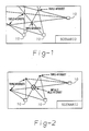
- FIG. 1 there is shown a description of the target identification problem for the case of angle-only data from three sensors.
- the individual sensors 10 detect the presence of targets at a given angle.
- each sensor has made three identifications of targets and will provide three angles as output. From these angles, individual lines or strobes can be drawn. Each point where three strobes intersect represents a triple intersect. Each triple intersect is a potential target.
- the desired solution to the deghosting problem is shown in FIG. 2. Three of the intersects here have been identified as valid intersects, or targets, while one intersect has been identified as a ghost.
- the analog associative processor 12 is a multi-layer analogue, or replica, of the real world sensor emplacements, angular resolutions and system X-Y resolutions.
- the sensors are placed in the analog associative processor 12 in positions that correspond to their position in the real world.
- a series of conductive lines radiating from each sensor correspond to all possible sensor angles, or strobes.
- a grid of conductive traces correspond to lines in the X-Y coordinate system. The actual hardware to implement various layers containing each set of lines will be discussed in more detail below.
- Step 14 the angular data is obtained from each sensor. This may be a digital representation of the data having an arbitrary resolution.
- all the triple intersects are found and the (x,y) coordinate locations for the intersects are determined, and all (x,y) locations are initially assumed to be valid (Step 16).
- the intersects may be found by pulsing all combinations of all actual strobe lines, such as those shown in FIG. 4 for all sensors, and detecting pulses exceeding a threshold T1 at the X-Y intersect coordinates.
- the detection may be by means of sensing conductive traces corresponding to the (x,y) coordinates in layers adjacent to the conductive traces representing the strobe lines.
- the pulse may be induced in the adjacent layers by means of capacitive coupling, as will be described in more detail below.
- Threshold T1 may be a voltage level that may be fixed, or may be adaptive so that, based on previous processing experience, the threshold T1 may be corrected to improve the performance of the analog associative processor 12.
- a valid intersect (x,y) is pulsed (Step 18). This may be accomplished by injecting a known voltage level into the circuit at the given coordinate via the conductive X-Y traces shown in FIG. 4. The pulse is then sensed at another intersect point (x,y) (Step 20). The pulse is transmitted from the X-Y intersect along the strobe conductive traces and on to the X-Y intersects between the various layers of the analog associative processor 12. Sensing may be accomplished by separate sensor circuits as will be described in more detail below. If the sensed pulse exceeds a threshold T2, then an accumulator is incremented for that intersect (x,y) (Step 22). T2, like T1, may be fixed or may be adaptive.
- Step 24 The fact that threshold T2 is exceeded will indicate that there is another intersect line on one of the same strobes as the pulse triple intersect. Steps 20 and 22 are then repeated for every other intersect (x,y). It should be noted that each time steps 20 and 22 are repeated, additional pulses will be transmitted to the valid triple intersect as indicated in step 18. Once all the intersects have been sensed, steps 18, 20 and 22 are again repeated for a second valid intersect, and pulses from that second valid intersect are sensed for all the remaining intersects. Once steps 18, 20 and 22 have been performed for each intersect, those intersects for which the accumulator has been incremented a number of times exceeding T3 are declared invalid (Step 24).
- N is equal to the number of strobes from the sensor having the minimum number of target strobes (Step 26). N will also equal the number of targets. If more intersects than targets are present then the analog associative processor 12 will clear the accumulator for the remaining valid intersects and will repeat steps 18, 20, 22, 24 and 26. When the number of remaining valid intersects is equal to the number of targets, the remaining (x,y) intersects are declared to be true target locations and this information is reported to the host CPU (not shown) (Step 28).
- the X-Y traces may be implemented as conductive lines, such as copper lines on a printed circuit substrate. Layers one and five contain lines corresponding to the X lines. Layers three and seven contain lines corresponding to the Y lines. Layers two, four and six correspond to all possible sensor angles from each of the sensors one, two and three respectively. It is noted that each line shown on FIG. 4 is implemented in at least one layer in FIG. 5. Repetitive layers of the same pattern are used in order to insure maximum coupling among adjacent layers.
- Each layer is arbitrarily thin and is separated from all adjacent layers by an arbitrarily thin dielectric. It is preferred that each layer containing sensor strobe lines be sandwiched between two layers containing the X and the Y coordinate lines. It may be desirable to cover the multi-layer substrate of the analog associative processor 12 above and/or below by a ground plane to shield it from unwanted electromagnetic interference.
- FIG. 6 there is shown an alternative embodiment of the analog associative processor 12 in accordance with the present invention.
- This embodiment differs from that shown in FIG. 5 by the use of conductive pads 32 at each (x,y) intersection.
- it is the array of conductive patches 32 which follow the prescribed geometric lines for the X-Y pattern layers shown in FIG. 5.
- the traces for the sensor strobe layers remain solid lines.
- each conductive pad 32 is independently accessible through independent access lines 34.
- the embodiment shown in FIG. 6 is more expensive than the embodiment shown in FIG. 5, since it requires the manufacture of separate pads 32 and access lines 34. However, it provides improved coupling between layers so that less sensitive sensor circuitry is required.
- FIG. 7 the seven layers in FIG. 5 are shown in their respective positions in the analog associative processor 12. Also, the X-Y access lines 34 are shown. However, the bundle of individual access lines shown in FIG. 6 are depicted as single lines in FIG. 7. Additional layers which may be required for access lines 34 are also not shown. Sensor layer access lines 36 are also shown connecting each of the three sensor layers. Again, individual lines permitting access to each strobe line on the sensor layers are shown as one single line 36 in FIG. 7.
- FIG. 8 the functional description of the total board layout of the analog associative processor 12 is shown.
- X-Y drivers/sensors 38 are connected to the traces in the X-Y layers, shown in FIG. 5, or alternatively, to each individual conductive pad 32 shown in FIG. 6.
- a group of Sensor drivers/sensors 40 are connected to the traces on the sensor strobe lines through access lines 36.
- the X-Y drivers/sensors 38 perform the function of initiating the pulses at (x,y) locations corresponding to intersects of the strobe lines. Initiation of the pulses is described in step 18 in FIG. 3.
- the X-Y drivers/sensors 38 also perform the function of detecting the pulses at the (x,y) locations corresponding to the other intersects.
- the Sensor driver/sensors 40 perform the function of pulsing the strobes from the sensor data to produce signals at all the intersects of the strobe lines. This signal is then detected on the (x,y) coordinates by the X-Y driver/sensors 38. This corresponds to step 16 in FIG. 3.
- the processing performed by the analog associative processor 12 is as follows.
- the initial inputs indicating the strobe angles for each strobe for each sensor is fed to the analog associative processor 12 by a host processor (not shown) to an interface circuit 42 shown in FIG. 8.
- This information is then fed from the interface circuit 42 to a control circuit 44.
- the control circuit 44 directs the information to the Sensor driver/sensor 40 which will excite the traces corresponding to the sensor angles.
- the above processing may be accomplished in a number of ways by the control circuit 44 and the Sensor driver/sensors 40.
- the processing may be in the amplitude domain, where single pulses are appropriately timed and sensed via threshold levels to direct a signal to the appropriate trace.
- the processing may be in the frequency domain where signals of the appropriate frequency content are used and localized combinations sensed using the appropriate filters.
- the X-Y driver/sensor 38 will find the (x,y) intersect having a response that exceeds T1 to detect all of the intersects.
- the transmission of the pulses from the sensor traces to the X-Y traces will be caused by signal coupling between layers in the multi-layer substrate of the analog associative processor 12.
- signal coupling between layers in the multi-layer substrate of the analog associative processor 12.
- other means of coupling are possible, such as magnetic or optical coupling between the successive layers.
- some of the functions of the analog associative processor 12 may be implemented with optical components.
- the remaining steps, 18 through 30 in FIG. 3, are performed by the X-Y driver/sensor 38 under the control of the control circuit 44.
- the (x,y) locations of the targets may be sent from the control circuit 44 to the interface circuit 42 and to the host processor.
- the analog associative processor 12 described above is inexpensive to produce using conventional printed circuit board technology and requires only simple support circuitry. Moreover, it performs deghosting of angle-only data at extremely high speeds. It is estimated that using one nanosecond pulses in the amplitude domain, fifty targets may be located, with no false targets, using three fixed sensor sites, in approximately 40 milliseconds. This is at least three to four orders of magnitude faster than software implementations using integer programming algorithms. Even higher speeds are obtainable, limited by support circuitry and by millimeter wave effects in the multi-layer printed circuit substrate itself.
Landscapes
- Engineering & Computer Science (AREA)
- Physics & Mathematics (AREA)
- Theoretical Computer Science (AREA)
- General Physics & Mathematics (AREA)
- Computer Hardware Design (AREA)
- General Engineering & Computer Science (AREA)
- Radar, Positioning & Navigation (AREA)
- Remote Sensing (AREA)
- Computing Systems (AREA)
- Databases & Information Systems (AREA)
- Data Mining & Analysis (AREA)
- Mathematical Physics (AREA)
- Software Systems (AREA)
- Measurement Of Length, Angles, Or The Like Using Electric Or Magnetic Means (AREA)
- Measurement Of Velocity Or Position Using Acoustic Or Ultrasonic Waves (AREA)
- Length Measuring Devices With Unspecified Measuring Means (AREA)
- Nuclear Medicine (AREA)
- Position Fixing By Use Of Radio Waves (AREA)
- Measurement Of Radiation (AREA)
- Radar Systems Or Details Thereof (AREA)
Applications Claiming Priority (2)
| Application Number | Priority Date | Filing Date | Title |
|---|---|---|---|
| US255205 | 1988-10-07 | ||
| US07/255,205 US4914604A (en) | 1988-10-07 | 1988-10-07 | Processor for analyzing angle-only data |
Publications (2)
| Publication Number | Publication Date |
|---|---|
| EP0362873A2 true EP0362873A2 (de) | 1990-04-11 |
| EP0362873A3 EP0362873A3 (de) | 1990-10-03 |
Family
ID=22967302
Family Applications (1)
| Application Number | Title | Priority Date | Filing Date |
|---|---|---|---|
| EP19890118595 Withdrawn EP0362873A3 (de) | 1988-10-07 | 1989-10-06 | Analog-Assoziativprozessor für die Ziellokalisierung bei Nur-Winkelinformationen |
Country Status (5)
| Country | Link |
|---|---|
| US (1) | US4914604A (de) |
| EP (1) | EP0362873A3 (de) |
| JP (1) | JPH0315782A (de) |
| KR (1) | KR920005238B1 (de) |
| AU (1) | AU622714B2 (de) |
Families Citing this family (18)
| Publication number | Priority date | Publication date | Assignee | Title |
|---|---|---|---|---|
| US5001631A (en) * | 1988-10-07 | 1991-03-19 | Hughes Aircraft Company | Cellular network assignment processor using randomly triggered adaptive cell thresholds |
| US5093781A (en) * | 1988-10-07 | 1992-03-03 | Hughes Aircraft Company | Cellular network assignment processor using minimum/maximum convergence technique |
| US5033020A (en) * | 1989-02-08 | 1991-07-16 | Grumman Aerospace Corporation | Optically controlled information processing system |
| US5276770A (en) * | 1989-08-11 | 1994-01-04 | Hughes Aircraft Company | Training of neural network for multi-source data fusion |
| US5050096A (en) * | 1989-09-26 | 1991-09-17 | Northrop Corporation | Path cost computing neural network |
| US5267502A (en) * | 1991-05-08 | 1993-12-07 | Sd-Scicon Uk Limited | Weapons systems future muzzle velocity neural network |
| US5604683A (en) * | 1991-09-12 | 1997-02-18 | Lockheed Martin Corporation | Evaluating target tracking when using multiple sensors |
| US5390679A (en) * | 1993-06-03 | 1995-02-21 | Eli Lilly And Company | Continuous cardiac output derived from the arterial pressure waveform using pattern recognition |
| US5680514A (en) * | 1994-09-23 | 1997-10-21 | Hughes Electronics | Multiple elastic feature net and method for target deghosting and tracking |
| SE515621C2 (sv) * | 1995-05-08 | 2001-09-10 | Ericsson Telefon Ab L M | Förfarande vid lägesbestämning |
| US5877722A (en) * | 1997-08-25 | 1999-03-02 | Hughes Electronics Corporation | Search method for detection and tracking of targets using multiple angle-only sensors |
| US6522288B1 (en) * | 2002-01-09 | 2003-02-18 | M/A-Com, Inc. | Method and apparatus for determining location of objects based on range readings from multiple sensors |
| DE602008004075D1 (de) * | 2008-01-18 | 2011-02-03 | Mitsubishi Electric Corp | Mehrfache Objektlokalisierung mithilfe eines Netzwerks von Empfängern |
| US7966147B2 (en) * | 2008-04-07 | 2011-06-21 | Raytheon Company | Generating images according to points of intersection for integer multiples of a sample-time distance |
| US20110110557A1 (en) * | 2009-11-06 | 2011-05-12 | Nicholas Clark | Geo-locating an Object from Images or Videos |
| JP5301521B2 (ja) * | 2010-12-03 | 2013-09-25 | ブラザー工業株式会社 | 電波推定方法、及び電波推定プログラム、並びに電波推定装置 |
| JP5634423B2 (ja) * | 2012-03-02 | 2014-12-03 | 株式会社東芝 | 目標追跡装置、目標追跡プログラム、目標追跡システム、及び目標追跡方法 |
| US20210389071A1 (en) * | 2020-06-10 | 2021-12-16 | David H. Sitrick | Automatic Weapon Subsystem Selecting Target, ID Target, Fire |
Family Cites Families (13)
| Publication number | Priority date | Publication date | Assignee | Title |
|---|---|---|---|---|
| US3323128A (en) * | 1964-09-01 | 1967-05-30 | George J Vogel | Multiple target tracking system |
| US3950733A (en) * | 1974-06-06 | 1976-04-13 | Nestor Associates | Information processing system |
| GB1572903A (en) * | 1976-06-30 | 1980-08-06 | Mcgeoch I | Method and appratus for identifying radar targets |
| DE2818942C2 (de) * | 1978-04-28 | 1986-03-27 | Zellweger Uster Ag, Uster | Verfahren zur Raumüberwachung und Vorrichtung zur Durchführung des Verfahrens |
| US4254474A (en) * | 1979-08-02 | 1981-03-03 | Nestor Associates | Information processing system using threshold passive modification |
| US4320287A (en) * | 1980-01-25 | 1982-03-16 | Lockheed Electronics Co., Inc. | Target vehicle tracking apparatus |
| US4326259A (en) * | 1980-03-27 | 1982-04-20 | Nestor Associates | Self organizing general pattern class separator and identifier |
| US4449127A (en) * | 1981-03-10 | 1984-05-15 | Westinghouse Electric Corp. | System and method for tracking targets in a multipath environment |
| US4450530A (en) * | 1981-07-27 | 1984-05-22 | New York University | Sensorimotor coordinator |
| JPS5965780A (ja) * | 1982-10-08 | 1984-04-14 | Hitachi Ltd | 相関判定方法 |
| US4589079A (en) * | 1983-04-14 | 1986-05-13 | Ficht Gmbh | Evaluation circuit for the signals from an array of N photoconductors which are successively scanned in a fast rhythm |
| US4591980A (en) * | 1984-02-16 | 1986-05-27 | Xerox Corporation | Adaptive self-repairing processor array |
| US4746770A (en) * | 1987-02-17 | 1988-05-24 | Sensor Frame Incorporated | Method and apparatus for isolating and manipulating graphic objects on computer video monitor |
-
1988
- 1988-10-07 US US07/255,205 patent/US4914604A/en not_active Expired - Fee Related
-
1989
- 1989-10-05 KR KR1019890014394A patent/KR920005238B1/ko not_active Expired
- 1989-10-05 AU AU42598/89A patent/AU622714B2/en not_active Expired - Fee Related
- 1989-10-06 EP EP19890118595 patent/EP0362873A3/de not_active Withdrawn
- 1989-10-06 JP JP1261931A patent/JPH0315782A/ja active Pending
Also Published As
| Publication number | Publication date |
|---|---|
| AU622714B2 (en) | 1992-04-16 |
| JPH0315782A (ja) | 1991-01-24 |
| KR900006876A (ko) | 1990-05-09 |
| EP0362873A3 (de) | 1990-10-03 |
| AU4259889A (en) | 1990-07-05 |
| US4914604A (en) | 1990-04-03 |
| KR920005238B1 (ko) | 1992-06-29 |
Similar Documents
| Publication | Publication Date | Title |
|---|---|---|
| US4914604A (en) | Processor for analyzing angle-only data | |
| EP2338104B1 (de) | Verfahren und vorrichtung zum detektieren eines mehrfachberührungsereignisses in einer optischen berührungsempfindlichen einrichtung | |
| US3985024A (en) | Acoustic emission process and system for improved flaw source location | |
| EP0393541A2 (de) | Gruppenbildungs- und Assoziationsprozessor | |
| US4851854A (en) | Memory intensive image sorter and method | |
| EP1234225A2 (de) | Vorrichtung und verfahren zur verbesserung der auflösung von infrarotberührungsempfindlichen systemen | |
| CN113391270A (zh) | 多雷达点云融合的虚假目标抑制方法、装置及终端设备 | |
| CN113391305A (zh) | 多雷达融合的虚假目标抑制方法、装置及终端设备 | |
| CN113138367B (zh) | 一种目标定位方法、装置、电子设备及存储介质 | |
| US5001631A (en) | Cellular network assignment processor using randomly triggered adaptive cell thresholds | |
| US5912985A (en) | Pattern detection method | |
| US4317186A (en) | Device for determining the position of a sound source | |
| WO2020249526A1 (en) | Touch-sensitive apparatus and method | |
| KR920005236B1 (ko) | 파면 벡터 상관 인자 프로세서 및 이의 상관방법 | |
| US5093781A (en) | Cellular network assignment processor using minimum/maximum convergence technique | |
| US4920506A (en) | Ultra-high speed two-dimensional coordinate transform processor | |
| EP0199910A2 (de) | Vorrichtung zur Erfassung des Orts eines Objekts auf einem Tablett | |
| EP0585035B1 (de) | Realzeit-Zusammenhangalgorithmussystem | |
| EP0838066B1 (de) | Graphische tafel | |
| JPS5943778B2 (ja) | 位置入力装置 | |
| CN120371161A (zh) | 触摸定位方法、红外触控框、红外触控屏以及电子设备 | |
| CN117991253A (zh) | 用于计算雷达感知目标物的速度的方法和毫米波雷达系统 | |
| EP4605818A1 (de) | Berührungsempfindliche vorrichtung und verfahren | |
| WO2022258949A1 (en) | Touch-sensitive apparatus and method | |
| JPH011989A (ja) | レ−ダ信号処理装置 |
Legal Events
| Date | Code | Title | Description |
|---|---|---|---|
| PUAI | Public reference made under article 153(3) epc to a published international application that has entered the european phase |
Free format text: ORIGINAL CODE: 0009012 |
|
| 17P | Request for examination filed |
Effective date: 19891031 |
|
| AK | Designated contracting states |
Kind code of ref document: A2 Designated state(s): DE GB |
|
| PUAL | Search report despatched |
Free format text: ORIGINAL CODE: 0009013 |
|
| AK | Designated contracting states |
Kind code of ref document: A3 Designated state(s): DE GB |
|
| STAA | Information on the status of an ep patent application or granted ep patent |
Free format text: STATUS: THE APPLICATION HAS BEEN WITHDRAWN |
|
| 18W | Application withdrawn |
Withdrawal date: 19920708 |