EP0362932A1 - Badewanne mit selbsttragenden Wänden - Google Patents
Badewanne mit selbsttragenden Wänden Download PDFInfo
- Publication number
- EP0362932A1 EP0362932A1 EP89202428A EP89202428A EP0362932A1 EP 0362932 A1 EP0362932 A1 EP 0362932A1 EP 89202428 A EP89202428 A EP 89202428A EP 89202428 A EP89202428 A EP 89202428A EP 0362932 A1 EP0362932 A1 EP 0362932A1
- Authority
- EP
- European Patent Office
- Prior art keywords
- shell
- bathtub
- hollow
- tub
- ribs
- Prior art date
- Legal status (The legal status is an assumption and is not a legal conclusion. Google has not performed a legal analysis and makes no representation as to the accuracy of the status listed.)
- Granted
Links
Images
Classifications
-
- A—HUMAN NECESSITIES
- A47—FURNITURE; DOMESTIC ARTICLES OR APPLIANCES; COFFEE MILLS; SPICE MILLS; SUCTION CLEANERS IN GENERAL
- A47K—SANITARY EQUIPMENT; ACCESSORIES THEREFOR, e.g. TOILET ACCESSORIES
- A47K3/00—Baths; Showers; Appurtenances therefor
- A47K3/02—Baths
Definitions
- Bathtub provided with modularly arranged strengthening areas, in order to produce a selfsustaining structure with so thin walls that the outside of the tub repeats the inside thereof, allowing to pile-up, for storing and shipping, a plurality of tubs.
- Present invention pertains to bathtubs and in particular bathtubs manufactured from plastic materials.
- plastic material bathtubs Today there is the use of manufacturing plastic material bathtubs for reasons of low cost and easy working.
- the process used to be followed is that of vacuum thermoshaping through which a plastic material sheet, for example from methyl metacrylate, usually well stiff at ambient temperature as well as at the usual temperature of hot water in a bathtub, is heated to the softening point and laid down against a hollow mold by applying a vacuum at suitable points.
- bathtub shells with such a selfsustaining structure to prevent substantial distortions thereof under usual strains due to use or piling-up, but altogether so thin to allow piling-up with entry of any shell in each other leading to both storage and shipping space substantial economies.
- a tub manufacture comprising a simple completely selfsustaining shell characteried by having inserted a rib structure, consisting of a modular grid, having the duty, of uniformely distribute in said shell the strains due to the load of water and, possibly, or a person lying in said tub, said strains loading, by means of said ribs or ridges, mainly supports under the bottom of said tub.
- said modular structure comprises a radial rib assembly depending from a shell edge and joining in a point on the bottom thereof, said ribs starting from points distributed on said shell edge in order to form a rectangular grid with substantially uniform members having the duty of distributing the most uniformly the possible said strains.
- said ribs converging on the bottom are connected each other by curved surfaces, either hollow or convex with respect to the shell inside, giving the shell an appearance as of a sea shell and a particularly high strength.
- the curved surfaces connecting said ribs are arranged symmetrically around a longitudinal axis of said shell with a hollow first major surface, symmetrically divided by said longitudinal axis, going from the upper edge at the head side to the convergence point of the ribs on the bottom of the shell, flanked by two hollow curved surfaces in turn adjacent third hollow surfaces continuining in fourth surfaces, which can be either hollow or convex, in turn continuing in fifth hollow surfaces adjacent a last hollow surface symmetrically divided by said shell longitudinal axis at the foot side of the tub.
- said first hollow major surface is so shaped to form an anatomic back.
- said two second hollow surfaces, adjacent said first hollow surface form niches delimited at half height by bottom planes forming two arms.
- said fourth curved convex surfaces end as lowered with respect to the tub edge forming two support planes symmetrically arranged with respect to the longitudinal axis of the tub itself.
- said modular shell structure is formed by an assembly of protruding and re-entring areas connected by ribs similar to the ribs sustaining a boat planking, which are formed by connecting surfaces between said protruding areas and said re-entring areas, said ribs being arranged in two substantially perpendicular groups each other intersecting in order to form a rectangular grid having substantially uniform members and having the duty of distributing the most uniformely the possible said strains.
- the areas protruding to inside said shell form as two substantially perpendicular bands of which a first major band is parallel and symmetric with respect to a longitudinal axis of said shell and a second minor band is substantially perpendicular with respect to said first major band intersecting it at a place substantially near the foot side of said shell.
- said first major band is shaped at the head side of said shell in order to form an anatomic back.
- two re-entring areas adjacent said major band at head side are provided with two niches delimited at half height by bottom planes forming two arms.
- said second protruding minor band ends against the edge of the tub with two lowered areas forming two support planes symmetrically arranged with respect to the longitudinal axis of the shell itself.
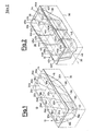
- the first tub 10 embodiment having selfsustaining walls according to the present invention, consists of a shell 12, formed for example by vacuum themoshaping of a thermoplastic material sheet, comprising an edge 14 according to a substantially rectangular frame from which depends a hull 16 forming the part of the tub intended to contain the water. From the edge 14 along the internal walls of the tub depend ribs or ridges 18a-l which, starting from points 20a-l on the edge of the hull 16, descend to a connection area 22 usually strengthened for housing accesories such as the tub drain.
- the points 20a-l are arranged in order to lay on a grid having rectangular substantially regular loops formed by intersecting straight lines 24a-e which provides a substantially uniform distribution of the strains on the hull 16 due to the presence of water and/or of the body of a person in the tub 10.
- said tub 10 abuts in a usual way with its bottom and edge 14 on a structure 26, such as a brick wall structure tiled or panelled, and also on the floor of the room in which the bathtub is installed.
- a selfsustaining wall tub 30 consists of a shell 32 also formed by vacuum thermoshaping from a thermoplastic material sheet, comprising an edge 34 according to a rectangular fram frome which a hull 36, forming the part of the tub intedend to contain water, descends.
- the internal walls of the hull 36 have two inside protruding areas of which a first major area or band 38 is arranged parallel and symmetric with respect to a longitudinal axis 39 of the tub itself and a minor area or band 40 is sustantially perpendicular with respect to the major area 38 crossing the same near the foot side of the tub.
- the two band areas 38 and 40 delimit adjacent lowered areas 42a-f, of which two areas 42b and 42e have intermediate depth and four areas 42a, 42c, 42d, and 42f are the deepest, forming among them rib connections 44a-l having a strengthening duty similar to that of the ribs of a boat hull.
- the rib connections 44a-l are in line with straight lines 45a-e crossing each other to form a grid having rectangular uniform loops providing a substantially uniform distribution of the strains applied to the hull 36 by the presence of water and/or the body of a person in the bathtub itself.
- said tub 30, showing on the external wall of its hull 36 re-entring band areas 46 and 48 respectively corresponding to band areas 38 and 40 inside protruding, abuts in a usual way with its bottom and the edge 34 against a structure 50, such as a brick structure, tilable or panelable for aesthetic purposes, as well as on the floor of the room in which the bathtub is installed.
- a structure 50 such as a brick structure, tilable or panelable for aesthetic purposes, as well as on the floor of the room in which the bathtub is installed.
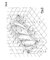
- FIG 3 it is seen an installed bathtub having ribbed shell embodied according to figure 1 example.
- a bathtub manufactured according to the tub 10, having the ribbed shell 12 of figure 1.
- Said tub surrounded and supported by a brick structure, defined by the tiled walls 66 and 68, comprises a rectangular frame edge 74 from which descends a ribbed shell 76 provided with ribs protruding to the inside indicating the limits among hollow surfaces such as the surfaces 78a-h, or between hollow and convex surfaces, such as the surfaces 80a and 80b terminating a little below the rectangular edge 74 for defining two article support planes 82a and 82b.
- hollow surfaces 78b and 78h are formed as deep niches housing, at half height, support planes having duty of arms 84 and 85 and the hollow surface 78a is so shaped to form an anatomic back affording particular comfort to the bathtub.
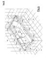
- a bathtub manufactured according to the tub 30, having ribbed shell 32 of figure 2.
- Said tub surrounded and supported by a brick structure defined by the tiled walls 66 and 68, comprises a rectangular frame edge 94 from which descends a ribbed shell 96 provided with a first major raised band area 98 arranged according to the length of the tub, and with a second minor raised band area 100 substantially perpendicular with respect to the major band area 98, said band area 100 terminating with two planes 102a and 102b a little below the frame 94 operating as article supporting planes.
- the raised band 98 is surrounded by two lowered niches 104a and 104b, terminating at half height with two planes 106a, and 106b, operating as arms.
- the major raised band 98 is shaped at the head side to form an anatomic back 110 affording particular comfort to the tub.
- a further thickness step 112 at half height supplies a supplementar or izontal rib further cooperating to strengthen the shell 96.
Landscapes
- Health & Medical Sciences (AREA)
- Public Health (AREA)
- Epidemiology (AREA)
- General Health & Medical Sciences (AREA)
- Bathtubs, Showers, And Their Attachments (AREA)
- Devices For Medical Bathing And Washing (AREA)
- Cultivation Receptacles Or Flower-Pots, Or Pots For Seedlings (AREA)
Applications Claiming Priority (2)
| Application Number | Priority Date | Filing Date | Title |
|---|---|---|---|
| IT2216388 | 1988-10-03 | ||
| IT8822163A IT1227267B (it) | 1988-10-03 | 1988-10-03 | Vasca da bagno a pareti autoportanti. |
Publications (2)
| Publication Number | Publication Date |
|---|---|
| EP0362932A1 true EP0362932A1 (de) | 1990-04-11 |
| EP0362932B1 EP0362932B1 (de) | 1993-07-28 |
Family
ID=11192441
Family Applications (1)
| Application Number | Title | Priority Date | Filing Date |
|---|---|---|---|
| EP89202428A Expired - Lifetime EP0362932B1 (de) | 1988-10-03 | 1989-09-28 | Badewanne mit selbsttragenden Wänden |
Country Status (4)
| Country | Link |
|---|---|
| EP (1) | EP0362932B1 (de) |
| DE (1) | DE68907842T2 (de) |
| ES (1) | ES2044064T3 (de) |
| IT (1) | IT1227267B (de) |
Cited By (3)
| Publication number | Priority date | Publication date | Assignee | Title |
|---|---|---|---|---|
| WO1992007147A1 (en) * | 1990-10-16 | 1992-04-30 | American Standard Inc. | Bathtub assembly having contoured walls and accessories |
| JP2015188482A (ja) * | 2014-03-27 | 2015-11-02 | Toto株式会社 | 浴槽 |
| WO2018158991A1 (ja) * | 2017-02-28 | 2018-09-07 | Toto株式会社 | 浴槽 |
Families Citing this family (2)
| Publication number | Priority date | Publication date | Assignee | Title |
|---|---|---|---|---|
| US7802324B2 (en) * | 2003-12-23 | 2010-09-28 | 2033875 Ontario Inc. | Modular prefabricated spa |
| USD575406S1 (en) | 2003-12-23 | 2008-08-19 | Jack Layfield | Water spa |
Citations (5)
| Publication number | Priority date | Publication date | Assignee | Title |
|---|---|---|---|---|
| US3421162A (en) * | 1966-10-03 | 1969-01-14 | Coleco Ind Inc | Recreational structure for pools and the like |
| US3793653A (en) * | 1972-05-17 | 1974-02-26 | Carolina Enterprises | One-piece plastic pool |
| DE2702295A1 (de) * | 1977-01-21 | 1978-07-27 | Ahlmann Sanitaer U Kunststofft | Einteilige badewanne |
| EP0126832A2 (de) * | 1983-05-31 | 1984-12-05 | K & Q KING AND QUEEN S.p.A. | Bett zum Transportieren und Unterstützen von Badewannen, insbesondere hergestellt aus synthetischem Material |
| DE8631326U1 (de) * | 1986-11-22 | 1988-01-07 | Kayser, Burkhard, 2906 Wardenburg | Warmwasserbecken |
-
1988
- 1988-10-03 IT IT8822163A patent/IT1227267B/it active
-
1989
- 1989-09-28 EP EP89202428A patent/EP0362932B1/de not_active Expired - Lifetime
- 1989-09-28 DE DE89202428T patent/DE68907842T2/de not_active Expired - Fee Related
- 1989-09-28 ES ES89202428T patent/ES2044064T3/es not_active Expired - Lifetime
Patent Citations (5)
| Publication number | Priority date | Publication date | Assignee | Title |
|---|---|---|---|---|
| US3421162A (en) * | 1966-10-03 | 1969-01-14 | Coleco Ind Inc | Recreational structure for pools and the like |
| US3793653A (en) * | 1972-05-17 | 1974-02-26 | Carolina Enterprises | One-piece plastic pool |
| DE2702295A1 (de) * | 1977-01-21 | 1978-07-27 | Ahlmann Sanitaer U Kunststofft | Einteilige badewanne |
| EP0126832A2 (de) * | 1983-05-31 | 1984-12-05 | K & Q KING AND QUEEN S.p.A. | Bett zum Transportieren und Unterstützen von Badewannen, insbesondere hergestellt aus synthetischem Material |
| DE8631326U1 (de) * | 1986-11-22 | 1988-01-07 | Kayser, Burkhard, 2906 Wardenburg | Warmwasserbecken |
Cited By (3)
| Publication number | Priority date | Publication date | Assignee | Title |
|---|---|---|---|---|
| WO1992007147A1 (en) * | 1990-10-16 | 1992-04-30 | American Standard Inc. | Bathtub assembly having contoured walls and accessories |
| JP2015188482A (ja) * | 2014-03-27 | 2015-11-02 | Toto株式会社 | 浴槽 |
| WO2018158991A1 (ja) * | 2017-02-28 | 2018-09-07 | Toto株式会社 | 浴槽 |
Also Published As
| Publication number | Publication date |
|---|---|
| EP0362932B1 (de) | 1993-07-28 |
| DE68907842T2 (de) | 1993-12-23 |
| IT8822163A0 (it) | 1988-10-03 |
| IT1227267B (it) | 1991-03-28 |
| DE68907842D1 (de) | 1993-09-02 |
| ES2044064T3 (es) | 1994-01-01 |
Similar Documents
| Publication | Publication Date | Title |
|---|---|---|
| US2415150A (en) | Pneumatic mattress | |
| US3671981A (en) | Invalid or geriatric toilet seat | |
| US4724560A (en) | Pillow utilizing air and water | |
| US20050039259A1 (en) | Plastic mattress foundation having a sculpted exterior surface | |
| CA2232657A1 (en) | Inflatable mattress with improved border support wall | |
| US4535494A (en) | Slat type mattress foundation | |
| EP0362932A1 (de) | Badewanne mit selbsttragenden Wänden | |
| CA2130923C (en) | Spacer for supporting water catchment basins | |
| USD322003S (en) | Non-slip surface unit for bathtubs or the like | |
| US4467485A (en) | Waterbed mattress with free floating baffle | |
| CN209678335U (zh) | 一种木塑浴缸壁板及浴缸 | |
| EP0362933A1 (de) | Badewannen und deren Herstellungsverfahren | |
| US3020561A (en) | Bathtub construction | |
| CN212972496U (zh) | 一种桌式美陈道具 | |
| JPH04282106A (ja) | 積み重ね可能な椅子 | |
| KR200164029Y1 (ko) | 베개 | |
| US2118717A (en) | Paper covered casket | |
| CN111910962A (zh) | 一种滚塑成型的厕屋 | |
| USD312357S (en) | Water mattress support | |
| JPH0123350Y2 (de) | ||
| KR900008818Y1 (ko) | 차배달용 가방 | |
| JPH0120916Y2 (de) | ||
| JPH0322641Y2 (de) | ||
| JPS6122560Y2 (de) | ||
| JPS62194356A (ja) | 床構造 |
Legal Events
| Date | Code | Title | Description |
|---|---|---|---|
| PUAI | Public reference made under article 153(3) epc to a published international application that has entered the european phase |
Free format text: ORIGINAL CODE: 0009012 |
|
| AK | Designated contracting states |
Kind code of ref document: A1 Designated state(s): DE ES FR GB SE |
|
| 17P | Request for examination filed |
Effective date: 19900905 |
|
| 17Q | First examination report despatched |
Effective date: 19920128 |
|
| GRAA | (expected) grant |
Free format text: ORIGINAL CODE: 0009210 |
|
| AK | Designated contracting states |
Kind code of ref document: B1 Designated state(s): DE ES FR GB SE |
|
| PGFP | Annual fee paid to national office [announced via postgrant information from national office to epo] |
Ref country code: FR Payment date: 19930729 Year of fee payment: 5 |
|
| PGFP | Annual fee paid to national office [announced via postgrant information from national office to epo] |
Ref country code: ES Payment date: 19930804 Year of fee payment: 5 |
|
| PGFP | Annual fee paid to national office [announced via postgrant information from national office to epo] |
Ref country code: SE Payment date: 19930809 Year of fee payment: 5 |
|
| REF | Corresponds to: |
Ref document number: 68907842 Country of ref document: DE Date of ref document: 19930902 |
|
| PGFP | Annual fee paid to national office [announced via postgrant information from national office to epo] |
Ref country code: GB Payment date: 19930921 Year of fee payment: 5 |
|
| PGFP | Annual fee paid to national office [announced via postgrant information from national office to epo] |
Ref country code: DE Payment date: 19930928 Year of fee payment: 5 |
|
| ET | Fr: translation filed | ||
| REG | Reference to a national code |
Ref country code: ES Ref legal event code: FG2A Ref document number: 2044064 Country of ref document: ES Kind code of ref document: T3 |
|
| PLBE | No opposition filed within time limit |
Free format text: ORIGINAL CODE: 0009261 |
|
| STAA | Information on the status of an ep patent application or granted ep patent |
Free format text: STATUS: NO OPPOSITION FILED WITHIN TIME LIMIT |
|
| 26N | No opposition filed | ||
| PG25 | Lapsed in a contracting state [announced via postgrant information from national office to epo] |
Ref country code: GB Effective date: 19940928 |
|
| PG25 | Lapsed in a contracting state [announced via postgrant information from national office to epo] |
Ref country code: SE Effective date: 19940929 Ref country code: ES Free format text: LAPSE BECAUSE OF EXPIRATION OF PROTECTION Effective date: 19940929 |
|
| EAL | Se: european patent in force in sweden |
Ref document number: 89202428.2 |
|
| GBPC | Gb: european patent ceased through non-payment of renewal fee |
Effective date: 19940928 |
|
| PG25 | Lapsed in a contracting state [announced via postgrant information from national office to epo] |
Ref country code: FR Effective date: 19950531 |
|
| PG25 | Lapsed in a contracting state [announced via postgrant information from national office to epo] |
Ref country code: DE Effective date: 19950601 |
|
| EUG | Se: european patent has lapsed |
Ref document number: 89202428.2 |
|
| REG | Reference to a national code |
Ref country code: FR Ref legal event code: ST |
|
| REG | Reference to a national code |
Ref country code: ES Ref legal event code: FD2A Effective date: 19990601 |