EP0363033A2 - Vorrichtung und Verfahren zum elektrischen Laden von schmelzgeblasenen Stoffbahnen - Google Patents
Vorrichtung und Verfahren zum elektrischen Laden von schmelzgeblasenen Stoffbahnen Download PDFInfo
- Publication number
- EP0363033A2 EP0363033A2 EP89309333A EP89309333A EP0363033A2 EP 0363033 A2 EP0363033 A2 EP 0363033A2 EP 89309333 A EP89309333 A EP 89309333A EP 89309333 A EP89309333 A EP 89309333A EP 0363033 A2 EP0363033 A2 EP 0363033A2
- Authority
- EP
- European Patent Office
- Prior art keywords
- die
- electrodes
- fiber
- electrode
- pins
- Prior art date
- Legal status (The legal status is an assumption and is not a legal conclusion. Google has not performed a legal analysis and makes no representation as to the accuracy of the status listed.)
- Withdrawn
Links
Images

Classifications
-
- B—PERFORMING OPERATIONS; TRANSPORTING
- B01—PHYSICAL OR CHEMICAL PROCESSES OR APPARATUS IN GENERAL
- B01D—SEPARATION
- B01D39/00—Filtering material for liquid or gaseous fluids
- B01D39/08—Filter cloth, i.e. woven, knitted or interlaced material
-
- D—TEXTILES; PAPER
- D01—NATURAL OR MAN-MADE THREADS OR FIBRES; SPINNING
- D01D—MECHANICAL METHODS OR APPARATUS IN THE MANUFACTURE OF ARTIFICIAL FILAMENTS, THREADS, FIBRES, BRISTLES OR RIBBONS
- D01D4/00—Spinnerette packs; Cleaning thereof
- D01D4/02—Spinnerettes
- D01D4/025—Melt-blowing or solution-blowing dies
-
- D—TEXTILES; PAPER
- D04—BRAIDING; LACE-MAKING; KNITTING; TRIMMINGS; NON-WOVEN FABRICS
- D04H—MAKING TEXTILE FABRICS, e.g. FROM FIBRES OR FILAMENTARY MATERIAL; FABRICS MADE BY SUCH PROCESSES OR APPARATUS, e.g. FELTS, NON-WOVEN FABRICS; COTTON-WOOL; WADDING ; NON-WOVEN FABRICS FROM STAPLE FIBRES, FILAMENTS OR YARNS, BONDED WITH AT LEAST ONE WEB-LIKE MATERIAL DURING THEIR CONSOLIDATION
- D04H1/00—Non-woven fabrics formed wholly or mainly of staple fibres or like relatively short fibres
- D04H1/40—Non-woven fabrics formed wholly or mainly of staple fibres or like relatively short fibres from fleeces or layers composed of fibres without existing or potential cohesive properties
- D04H1/54—Non-woven fabrics formed wholly or mainly of staple fibres or like relatively short fibres from fleeces or layers composed of fibres without existing or potential cohesive properties by welding together the fibres, e.g. by partially melting or dissolving
- D04H1/56—Non-woven fabrics formed wholly or mainly of staple fibres or like relatively short fibres from fleeces or layers composed of fibres without existing or potential cohesive properties by welding together the fibres, e.g. by partially melting or dissolving in association with fibre formation, e.g. immediately following extrusion of staple fibres
-
- B—PERFORMING OPERATIONS; TRANSPORTING
- B01—PHYSICAL OR CHEMICAL PROCESSES OR APPARATUS IN GENERAL
- B01D—SEPARATION
- B01D2239/00—Aspects relating to filtering material for liquid or gaseous fluids
- B01D2239/02—Types of fibres, filaments or particles, self-supporting or supported materials
- B01D2239/0216—Bicomponent or multicomponent fibres
- B01D2239/0225—Side-by-side
-
- B—PERFORMING OPERATIONS; TRANSPORTING
- B01—PHYSICAL OR CHEMICAL PROCESSES OR APPARATUS IN GENERAL
- B01D—SEPARATION
- B01D2239/00—Aspects relating to filtering material for liquid or gaseous fluids
- B01D2239/02—Types of fibres, filaments or particles, self-supporting or supported materials
- B01D2239/0241—Types of fibres, filaments or particles, self-supporting or supported materials comprising electrically conductive fibres or particles
-
- B—PERFORMING OPERATIONS; TRANSPORTING
- B01—PHYSICAL OR CHEMICAL PROCESSES OR APPARATUS IN GENERAL
- B01D—SEPARATION
- B01D2239/00—Aspects relating to filtering material for liquid or gaseous fluids
- B01D2239/04—Additives and treatments of the filtering material
- B01D2239/0435—Electret
-
- B—PERFORMING OPERATIONS; TRANSPORTING
- B01—PHYSICAL OR CHEMICAL PROCESSES OR APPARATUS IN GENERAL
- B01D—SEPARATION
- B01D2239/00—Aspects relating to filtering material for liquid or gaseous fluids
- B01D2239/06—Filter cloth, e.g. knitted, woven non-woven; self-supported material
- B01D2239/0604—Arrangement of the fibres in the filtering material
- B01D2239/0618—Non-woven
-
- B—PERFORMING OPERATIONS; TRANSPORTING
- B01—PHYSICAL OR CHEMICAL PROCESSES OR APPARATUS IN GENERAL
- B01D—SEPARATION
- B01D2239/00—Aspects relating to filtering material for liquid or gaseous fluids
- B01D2239/06—Filter cloth, e.g. knitted, woven non-woven; self-supported material
- B01D2239/0604—Arrangement of the fibres in the filtering material
- B01D2239/0622—Melt-blown
-
- B—PERFORMING OPERATIONS; TRANSPORTING
- B01—PHYSICAL OR CHEMICAL PROCESSES OR APPARATUS IN GENERAL
- B01D—SEPARATION
- B01D2239/00—Aspects relating to filtering material for liquid or gaseous fluids
- B01D2239/06—Filter cloth, e.g. knitted, woven non-woven; self-supported material
- B01D2239/065—More than one layer present in the filtering material
-
- B—PERFORMING OPERATIONS; TRANSPORTING
- B01—PHYSICAL OR CHEMICAL PROCESSES OR APPARATUS IN GENERAL
- B01D—SEPARATION
- B01D2239/00—Aspects relating to filtering material for liquid or gaseous fluids
- B01D2239/10—Filtering material manufacturing
Definitions
- This invention relates generally to a process and apparatus for producing fibrous electrically charged nonwoven webs.
- the invention relates to the manufacture of electrically charged meltblown fibrous materials by applying a charge to meltblown fibers during the meltblowing process.
- Meltblowing is a one step process in which a molten thermoplastic resin is extruded to form a plurality of fibers. Converging sheets of high velocity air blows the fibers unto a collector screen where they are entangled and collected forming a nonwoven web. These webs, called meltblown nonwoven fabrics, have excellent properties for many uses, one of which is filtration of gas and liquids.
- the microscopic diameters of the entangled fibers of the meltblown web are ideally suited for filtering finely divided particles out of a gaseous or liquid media. It is also known that filtration efficiency of these nonwoven materials can be improved by applying an electrostatic charge to the fibers. The charges on the webs are frequently called electrets.
- U.S. Patents which disclose nonwoven fibrous electrets include U.S. Patents 4,215,682, 4,375,718, 4,588,537, and 4,592,815.
- a process for applying the electric charge to the molten or hot fibers during the meltblowing process is disclosed in U.S. Patent 4,215,682.
- the electrostatic charging of the fibers in the hot or molten state of the polymer permits the charges to migrate into the polymer (since its electrical resistance is lower) and remain trapped upon cooling of the polymer. This increases the charge life of the electret.
- the charge is achieved by passing the extruded fibers through a electrostatlc field established by two charge sources, one source above and one below the extruded fiber stream.
- Each source includes an electrode wire and a ground shell.
- a high voltage charge to each electrode establishes an electrostatic field between the conductor wire and the ground.
- the intensive electrostatic field ionizes air or other gases around the conductor wire. (The effect may be enhanced by using a grounded shell around part of the conductor wire.)
- the ions and charged particles thus produced are propelled into the fibrous stream.
- a problem associated with this system is that of propelling the charged particles into the fiber stream, particularly at or near the die discharge where the fibers are the hottest. A substantial portion of the fiber stream does not pass through the corona zone.
- the patent states that the ions or charged particles are propelled into the stream by aerodynamics and electrostatic forces and that a fan may be used to assist this action.
- a meltblowing apparatus is equipped with an improved electrostatic charge system for creating a corona zone at or near the meltblowing die discharge.
- the meltblowing apparatus may be conventional comprising a die having a row of orifices through which molten thermoplastic resin is extruded forming a row of fibers. Converging hot air streams are blown on the fibers forming a fiber-air stream.
- the improved electrostatic charge system includes a pair of grounded electron emitter means mounted on the die (one on each side of the die discharge) and a pair of collector electrodes (one on each side of the fiber-air stream) which are connected to a high voltage source for charging the electrodes.
- the emitter means protrude outwardly from the die generally in the direction of the fiber-air stream flow and terminate near the die discharge.
- the electrostatic field between the electrodes and emitter means is established by high voltage charge which creates a corona zone at or near the die discharge.
- the electrons and ions in the corona zone thus contact the molten or hot fibers discharged from the die discharge. It is significant that the corona zone is at the grounded emitters and not the electrodes as taught by U.S. Patent 4,215,682. This establishes the corona zone at or near the die discharge.
- the preferred emitters are in the form of pins spaced along and on both sides of the die discharge. The tips of the pins are pointed and terminate near the die discharge.
- the process of the present invention is characterized by the steps of (a) extruding molten thermoplastic resin through a plurality of orifices to form a plurality of molten fibers, (b) blowing convergent hot air on both sides of the fibers to extend the fibers thereby forming a fiber-air stream, (c) establishing an electrostatic field between (i) two electrodes on either side of the stream and (ii) grounded electron emitters on either side of the die discharge whereby fibers passing between the emitters are charged; and (d) collecting the charged fibers to form a fibrous electrically charged web.
- An important feature of the invention is the high emission of electrons from the emitters, particularly from the emitter pins. This creates a corona zone at or near the die discharge. Unlike the system disclosed in U.S. Patent 4,215,682 the present invention avoids the problem of bringing the charged particles (essentially electrons and ions) in contact with the molten or hot fibers since the fibers-air stream flows essentially through the corona zone.
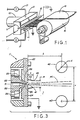
- a meltblown line with electrostatic charging equipment is illustrated in Figure 1 as comprising an extruder 10 for delivering molten resin to a meltblowing die 11 which extrudes fibers into converging hot air streams discharging a fiber-air stream 12 from the die discharge opening, and a rotating collector drum or screen 15 for separating the fibers and air.
- a web 16 is withdrawn from the screen 15.
- the typical meltblowing line will also include an air source connected to the die 11 through valved lines 17 and heating elements 18.
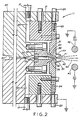
- the die 11 includes body members and 21, an elongate die nosepiece 22 secured to the die body and air knives 23 and 24.
- the nosepiece 22 has a converging section 29 of triangular cross section terminating at tip 30.
- a central elongate passage 31 is formed in the nosepiece 22 and a plurality of side-by-side orifices 32 are drilled in the tip 30.
- the die components are generally manufactured from high quality steal to provide durability. Molten polymer is delivered from the extruder through the die passages 33, 34 (coat hanger configuration) 35, 31, and extruded as a micro-sized side-by-side fibers from the orifices 32.
- the air knives 23 and 24 with the body members 20 and 21 define air passages 36 and 37.
- the air knives 23 and 24 have tapered inwardly facing surfaces which in combination with the tapered surfaces of the nosepiece 29 define converging air passages 38 and 39.
- the flow area of each air passage 38 and 39 is adjustable. Air is delivered from an air source via lines 17 through the air passages and is discharged onto opposite sides of the molten fibers as converging sheets of hot air.
- the converging sheets of hot air draw or attenuate the fibers forming a fiber and air stream 40 discharging from die discharge 41.
- the meltblowing apparatus shown in Figure 2 is provided with means for applying electrostatic charges to the fibers as they discharge from the die discharge opening 41.
- the electrostatic field is established by two electrodes 42 and 43, one placed above the stream 40 and the other below the stream 40 but equidistant from the center line of the stream 40.
- the center line of the stream is the direction of orientation of the orifices.
- the electrodes may be mounted on the same frame as that supporting the die to provide common ground.
- Protruding electron emitters are secured to the die air knives 23 and 24.
- the protruding emitters on either side of the die discharge 41 may be in a variety of shapes such as a blade or a wire
- the preferred emitters are pins 44 as illustrated.
- One row of pins 44 extends along the die above the die opening 41 and a second row of the pins extend along the die below the opening 41.
- the pins 44 are slanted toward the fiber-air stream and terminate in points 45.
- the slant angle of the pins 44 is not critical but serves to locate the pin tips 45 close to the fiber-air stream without interfering with the stream flow.
- a high voltage source is connected to electrodes (top/bottom) and the polarity is controlled so that the electrodes may have a +/+ charge, +/- charge, -/+ or -/- charge. This establishes a electrostatic field between the electrodes 42 and 43 and the grounded emitters 44. This in turn creates a corona zone around emitter tips 45 near the die discharge 41.
- the molten or hot fibers passing through the corona zone are charged by electrons or charged particles.
- the equipment for installation onto a meltblown line comprises the electrodes, a high voltage source, and the emitters. Specific examples of these components are described below.
- the electrodes 42 and 43 may be in the shape of metal (electrically conductive) bars as illustrated in the drawings.
- the bars may have a diameter ranging from 2" to a thin wire (e.g. 1/16 inch diameter).
- the electrode spacing should be as small as possible without interfering with the fiber-air stream flow. Electrode diameters of 1/8" to 1" are preferred.
- Also useable as electrodes are permeable, reticulated metal wires shaped as flat vanes or ovals. The openings between metal wires forming the fence-like or perforated material permits air to flow through the electrode with minimum interference of the fiber-air stream.
- the electrodes 42 and 43 regardless of shape and form, are mounted on insulators (e.g. ceramic) and connected to the high voltage source.
- any high voltage d.c. source may be used.
- the source should have variable voltage settings (e.g. between 10 KV and 25 KV) and preferably (-) and (+) polarity settings to permit adjustments in establishing the electrostatic field.
- a high voltage power source marketed by SIMCO, of Hatfield Penn. has proven quite adequate for purposes of this invention. This source has the following specification: Max. voltage - 25 kV DC Output polarity - neg. and pos. Max. current - 6.3 MA with electrode connected.
- the emitters are preferably in the form of sharp pointed electric conductive pins 44 spaced along and flanking the die discharge outlet 41.
- the pins are narrow having, for example, diameters in the range of 1/16 to 3/8 inch.
- the pins 44 may be mounted directly on the face of the air knives 23 and 24 as illustrated in Figures 2, 3, and 4 by welding or by insertion into properly drilled holes.
- the pins 44 are mounted on narrow plates 46 and 47 (as illustrated in Figure 5) which in turn are mounted on air knives 23 and 24 by means of threaded bolts 50 passing through slots 49. This arrangement permits adjustment of the vertical spacing of the pin tips 45.
- Also useable are a pair of grounded blades mounted on opposite sides of the die discharge and each having a sharp edge positioned near the die discharge outlet 41.
- a pair of wires flanking the die discharge outlet 41 may also be used.
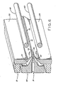
- FIG 6 Another preferred emitter construction is illustrated in Figure 6.
- the air knives 23 and 24 are provided with outwardly protruding lips 23a and 24a terminating in sharp edges 51 and 52.
- the edges 51 and 52 serve as the emitters in creating the corona zone.
- the emitters regardless of there form, are grounded.
- a combination of emitter construction may be used (e.g. protruding air knives with pins spaced thereon.)
- the bars 42 and 43 and emitter means should traverse the full length of the die discharge opening 41.
- the spacing (a) of pin ends 45 should be as close as possible without interfering with the flow of fiber in stream 40.
- the spacing (c) should be large, preferably about 0.2 to 0.6, most preferably 0.2 to 0.4, of (h) to localize the corona zone near outlet 41.
- the horizontal spacing (b) does not appear critical, provided sufficient corona zone is established along the length of the die discharge opening 41.
- the diameter (d) of the electrodes should be large (vis-a-vis a wire) but not so large as to interfere with fiber flow, and the spacings (v) and (h) should be small (close to the fiber-air stream 40 and the die 11 respectively).
- Dimensions (d) and (v) should be sized to avoid interference with the flow of fibers in stream 40.
- the dimension (h) should be greater than the distance between tips 45 and the axis of its associated bar to avoid electrical arcing between the bar and the die air knife.
- the electrostatic charge equipment will be mounted on a meltblowing line.
- the line may employ any of the thermoplastic resins capable of use in meltblowing.
- the preferred polymer is polypropylene, but other polymers may be used such as low and high density polyethylene, ethylene copolymers (including EVA copolymer), nylon, polyamide, polyesters, polystyrene, poly-4-methylpentene-1, polymethylmethacrylate, polytrifluorochloroethylene, polyurethanes, polycarbonates, silicones, and blends of these.
- the meltblowing line produces fibers less than 10 microns, typically 1 to 5 microns.
- the line is started and once steady state operation is achieved, the electrostatic charge system may be activated. Adjustments may be required to optimize performance of the electrostatic equipment.
- Meltblowing Die 20 inch width with twenty 0.015 orifices per inch; extrusion temp. 450° - 550°F; polymer flow rate: 0.2 to .8 grams per minute per orifice.
- Electrodes metal bars or wires
- Resin polypropylene (PP 3145 marketed by Exxon Chemical Co.)
- Aersosol 10% suspension of 0.8 micrometer latex spheres in a distilled water fog.
- the cone probe was vertically mounted with the large diameter end upward. A plastic spacer was placed on top of the cone.The height of the spacer required to give accurate voltage reading of a metal plate connected to a power supply was previously determined. Each web tested was placed on the plastic spacer. A grounded metal plate was then placed on the web and the test carried out to determine surface potential.
- Nonwoven webs were made under variable conditions (e.g. changes in voltage, polarity, and spacings) and tested for filtration efficiency and surface potential. Numerous tests were carried out. The data shown in Table I are representative of the tests. Table II represents comparative results for web prepared without charges.
Landscapes
- Engineering & Computer Science (AREA)
- Textile Engineering (AREA)
- Chemical & Material Sciences (AREA)
- Chemical Kinetics & Catalysis (AREA)
- Mechanical Engineering (AREA)
- Nonwoven Fabrics (AREA)
- Spinning Methods And Devices For Manufacturing Artificial Fibers (AREA)
Applications Claiming Priority (2)
| Application Number | Priority Date | Filing Date | Title |
|---|---|---|---|
| US245137 | 1981-03-18 | ||
| US07/245,137 US4904174A (en) | 1988-09-15 | 1988-09-15 | Apparatus for electrically charging meltblown webs (B-001) |
Publications (2)
| Publication Number | Publication Date |
|---|---|
| EP0363033A2 true EP0363033A2 (de) | 1990-04-11 |
| EP0363033A3 EP0363033A3 (de) | 1990-08-16 |
Family
ID=22925436
Family Applications (1)
| Application Number | Title | Priority Date | Filing Date |
|---|---|---|---|
| EP89309333A Withdrawn EP0363033A3 (de) | 1988-09-15 | 1989-09-14 | Vorrichtung und Verfahren zum elektrischen Laden von schmelzgeblasenen Stoffbahnen |
Country Status (3)
| Country | Link |
|---|---|
| US (1) | US4904174A (de) |
| EP (1) | EP0363033A3 (de) |
| JP (1) | JPH02234966A (de) |
Cited By (9)
| Publication number | Priority date | Publication date | Assignee | Title |
|---|---|---|---|---|
| WO1992005305A1 (en) * | 1990-09-24 | 1992-04-02 | Exxon Chemical Patents Inc. | Charging apparatus and method for meltblown webs |
| EP0518693A1 (de) * | 1991-06-12 | 1992-12-16 | Toray Industries, Inc. | Verfahren zur Herstellung von schlauchförmigem Vliesstoff sowie hergestellter Schlauchvliesstoff |
| EP0601278A1 (de) * | 1992-12-10 | 1994-06-15 | Firma Carl Freudenberg | Spinnrotor |
| WO2003022555A1 (en) * | 2001-09-07 | 2003-03-20 | S. C. Johnson Home Storage, Inc. | Method of producing an electrically charged film |
| US6635077B2 (en) | 2001-09-07 | 2003-10-21 | S.C. Johnson Home Storage, Inc. | Structure including a film material |
| WO2003106749A1 (en) * | 2002-06-15 | 2003-12-24 | Kimberly-Clark Worldwide, Inc. | Use of a pulsating power supply for electrostatic charging of nonwovens |
| WO2007022390A1 (en) * | 2005-08-17 | 2007-02-22 | E. I. Du Pont De Nemours And Company | Improved electroblowing fiber spinning process |
| DE102008047552A1 (de) * | 2008-09-16 | 2010-04-08 | Carl Freudenberg Kg | Elektretfilterelement und Verfahren zu dessen Herstellung |
| EP3778239A1 (de) * | 2019-08-16 | 2021-02-17 | FRAUNHOFER-GESELLSCHAFT zur Förderung der angewandten Forschung e.V. | Verfahren und vorrichtung zum parallelextrudieren von druckmedium auf ein substrat |
Families Citing this family (70)
| Publication number | Priority date | Publication date | Assignee | Title |
|---|---|---|---|---|
| WO1991019034A1 (en) * | 1990-05-29 | 1991-12-12 | Exxon Chemical Patents Inc. | Insulated collector for production of electrically charged meltblown webs |
| US5075068A (en) * | 1990-10-11 | 1991-12-24 | Exxon Chemical Patents Inc. | Method and apparatus for treating meltblown filaments |
| US5227172A (en) * | 1991-05-14 | 1993-07-13 | Exxon Chemical Patents Inc. | Charged collector apparatus for the production of meltblown electrets |
| US5196207A (en) * | 1992-01-27 | 1993-03-23 | Kimberly-Clark Corporation | Meltblown die head |
| US5486411A (en) * | 1992-03-26 | 1996-01-23 | The University Of Tennessee Research Corporation | Electrically charged, consolidated non-woven webs |
| US5441550A (en) * | 1992-03-26 | 1995-08-15 | The University Of Tennessee Research Corporation | Post-treatment of laminated nonwoven cellulosic fiber webs |
| USRE35206E (en) * | 1992-03-26 | 1996-04-16 | The University Of Tennessee Research Corporation | Post-treatment of nonwoven webs |
| US5244482A (en) * | 1992-03-26 | 1993-09-14 | The University Of Tennessee Research Corporation | Post-treatment of nonwoven webs |
| US5443606A (en) * | 1992-03-26 | 1995-08-22 | The University Of Tennessee Reserch Corporation | Post-treatment of laminated nonwoven cellulosic fiber webs |
| US5397413A (en) * | 1992-04-10 | 1995-03-14 | Fiberweb North America, Inc. | Apparatus and method for producing a web of thermoplastic filaments |
| US5254297A (en) * | 1992-07-15 | 1993-10-19 | Exxon Chemical Patents Inc. | Charging method for meltblown webs |
| US5531235A (en) * | 1992-09-28 | 1996-07-02 | Hassenboehler, Jr.; Charles B. | Cigarette filter micropleated web and method of manufacture |
| US5401446A (en) * | 1992-10-09 | 1995-03-28 | The University Of Tennessee Research Corporation | Method and apparatus for the electrostatic charging of a web or film |
| US5592357A (en) * | 1992-10-09 | 1997-01-07 | The University Of Tennessee Research Corp. | Electrostatic charging apparatus and method |
| US5686050A (en) * | 1992-10-09 | 1997-11-11 | The University Of Tennessee Research Corporation | Method and apparatus for the electrostatic charging of a web or film |
| CA2124237C (en) | 1994-02-18 | 2004-11-02 | Bernard Cohen | Improved nonwoven barrier and method of making the same |
| CA2136576C (en) | 1994-06-27 | 2005-03-08 | Bernard Cohen | Improved nonwoven barrier and method of making the same |
| US5665448A (en) * | 1994-08-24 | 1997-09-09 | Graham; Barbara | Electrostatic display device |
| WO1996017569A2 (en) | 1994-12-08 | 1996-06-13 | Kimberly-Clark Worldwide, Inc. | Method of forming a particle size gradient in an absorbent article |
| CA2153278A1 (en) | 1994-12-30 | 1996-07-01 | Bernard Cohen | Nonwoven laminate barrier material |
| US5955174A (en) * | 1995-03-28 | 1999-09-21 | The University Of Tennessee Research Corporation | Composite of pleated and nonwoven webs |
| US5496627A (en) * | 1995-06-16 | 1996-03-05 | Eastman Chemical Company | Composite fibrous filters |
| EP0801809A2 (de) * | 1995-06-19 | 1997-10-22 | The University Of Tennessee Research Corporation | Entladungsverfahren sowie elektroden zur erzeugung von plasma unter atmosphärendruck und materialen, die mit diesem verfahren behandelt werden |
| ZA965786B (en) | 1995-07-19 | 1997-01-27 | Kimberly Clark Co | Nonwoven barrier and method of making the same |
| US5834384A (en) | 1995-11-28 | 1998-11-10 | Kimberly-Clark Worldwide, Inc. | Nonwoven webs with one or more surface treatments |
| US5792242A (en) * | 1996-02-26 | 1998-08-11 | Minnesota Mining And Manufacturing Co. | Electrostatic fibrous filter web |
| IL119809A (en) * | 1996-12-11 | 2001-06-14 | Nicast Ltd | A device for the production of a complex material for filtration and a method for its application |
| US6422848B1 (en) | 1997-03-19 | 2002-07-23 | Nordson Corporation | Modular meltblowing die |
| US6537932B1 (en) | 1997-10-31 | 2003-03-25 | Kimberly-Clark Worldwide, Inc. | Sterilization wrap, applications therefor, and method of sterilizing |
| US6368409B1 (en) | 1997-11-25 | 2002-04-09 | Nordson Corporation | Electrostatic dispensing apparatus and method |
| US6365088B1 (en) | 1998-06-26 | 2002-04-02 | Kimberly-Clark Worldwide, Inc. | Electret treatment of high loft and low density nonwoven webs |
| US6110260A (en) * | 1998-07-14 | 2000-08-29 | 3M Innovative Properties Company | Filter having a change indicator |
| US6036752A (en) * | 1998-07-28 | 2000-03-14 | 3M Innovative Properties Company | Pleated filter |
| USD414855S (en) | 1998-07-28 | 1999-10-05 | 3M Innovative Properties Company | Pleated filter |
| US6123269A (en) * | 1998-10-30 | 2000-09-26 | Nordson Corporation | Liquid dispensing system and method for electrostatically deflecting a continuous strand of high viscosity viscoelastic nonconductive liquid |
| US6243909B1 (en) | 1999-02-01 | 2001-06-12 | Barbara Graham | Dust mop with replaceable electrostatically |
| US6428610B1 (en) * | 2000-01-18 | 2002-08-06 | The University Of Tennessee Research Corporation | Hepa filter |
| US6494921B1 (en) | 2000-02-10 | 2002-12-17 | M. Catherine Bennett | Method of removing particulate debris, especially dust mite fecal material from fabric articles in a conventional clothes dryer |
| US6533119B1 (en) | 2000-05-08 | 2003-03-18 | 3M Innovative Properties Company | BMF face oil remover film |
| US20070031607A1 (en) * | 2000-12-19 | 2007-02-08 | Alexander Dubson | Method and apparatus for coating medical implants |
| US20040030377A1 (en) * | 2001-10-19 | 2004-02-12 | Alexander Dubson | Medicated polymer-coated stent assembly |
| US20020084178A1 (en) | 2000-12-19 | 2002-07-04 | Nicast Corporation Ltd. | Method and apparatus for manufacturing polymer fiber shells via electrospinning |
| US7244272B2 (en) | 2000-12-19 | 2007-07-17 | Nicast Ltd. | Vascular prosthesis and method for production thereof |
| US6709623B2 (en) | 2000-12-22 | 2004-03-23 | Kimberly-Clark Worldwide, Inc. | Process of and apparatus for making a nonwoven web |
| EP1377419A4 (de) * | 2001-03-20 | 2004-05-26 | Nicast Ltd | Verfahren und vorrichtung zum verbessern mechanischer eigenschaften von vliesstoffen |
| DE10120223B4 (de) * | 2001-04-24 | 2005-08-25 | Carl Freudenberg Kg | Mehrlagiger Luftfilter und dessen Verwendung |
| US6514324B1 (en) | 2001-08-10 | 2003-02-04 | Rick L. Chapman | High efficiency active electrostatic air filter and method of manufacture |
| US6899931B2 (en) | 2001-09-07 | 2005-05-31 | S. C. Johnson Home Storage, Inc. | Film material |
| KR100438004B1 (ko) * | 2001-09-17 | 2004-07-02 | 한국과학기술연구원 | 부직포형 필터 소재 제조시스템 및 그 제조방법 |
| US6534129B1 (en) | 2001-10-30 | 2003-03-18 | Nordson Corporation | Electrostatic liquid dispensing apparatus and method |
| US7662332B2 (en) * | 2003-10-01 | 2010-02-16 | The Research Foundation Of State University Of New York | Electro-blowing technology for fabrication of fibrous articles and its applications of hyaluronan |
| US20080200975A1 (en) * | 2004-01-06 | 2008-08-21 | Nicast Ltd. | Vascular Prosthesis with Anastomotic Member |
| US8808608B2 (en) * | 2004-12-27 | 2014-08-19 | E I Du Pont De Nemours And Company | Electroblowing web formation process |
| JP2008535534A (ja) * | 2005-02-17 | 2008-09-04 | ナイキャスト リミテッド | 膨張可能な医療装置 |
| US7465159B2 (en) * | 2005-08-17 | 2008-12-16 | E.I. Du Pont De Nemours And Company | Fiber charging apparatus |
| DE102006048292A1 (de) * | 2006-10-12 | 2008-04-17 | Irema-Filter Gmbh | Verfahren zur Herstellung eines Faservlieses aus Kunststoff-Micro- und/oder Nanofasern |
| CZ2007729A3 (cs) * | 2007-10-18 | 2009-04-29 | Elmarco S. R. O. | Zarízení pro výrobu vrstvy nanovláken elektrostatickým zvláknováním polymerních matric a sberná elektroda pro takové zarízení |
| US20100007042A1 (en) * | 2008-07-09 | 2010-01-14 | Simmonds Glen E | Method and apparatus for making submicron diameter fibers and webs there from |
| JP5226558B2 (ja) * | 2009-02-16 | 2013-07-03 | パナソニック株式会社 | ナノファイバ製造装置、ナノファイバ製造方法 |
| CN102720003A (zh) * | 2012-05-15 | 2012-10-10 | 山东泰鹏无纺有限公司 | 提高涤纶纺粘非织造布均匀度的方法及静电分丝装置 |
| CN102787374B (zh) * | 2012-07-20 | 2015-02-25 | 东华大学 | 一种制备超细纤维的熔喷模头 |
| CZ304124B6 (cs) * | 2012-11-23 | 2013-11-06 | Nafigate Corporation, A.S. | Zpusob a zarízení pro výrobu nanovláken elektrostatickým zvláknováním roztoku nebo taveniny polymeru |
| CN103114341A (zh) * | 2013-02-22 | 2013-05-22 | 昆山鸿福泰环保科技有限公司 | 一种用于pp滤芯加工的喷丝嘴 |
| CN103628149B (zh) * | 2013-11-25 | 2015-10-14 | 北京化工大学 | 一种高压气流辅助喷头自旋转静电纺丝装置 |
| CN104088084B (zh) * | 2014-07-04 | 2016-08-24 | 江苏丽洋新材料股份有限公司 | 一种高效低阻空气过滤材料制备装置 |
| GB2579100A (en) * | 2018-11-23 | 2020-06-10 | Teknoweb Mat S R L | Spinneret block with readily exchangable nozzles for use in the manufacturing of meltblown fibers |
| CN109537068B (zh) * | 2018-12-19 | 2021-08-06 | 上海固甲新材料科技有限公司 | 一种液喷纺丝装置 |
| CN110230106A (zh) * | 2019-04-16 | 2019-09-13 | 天津工业大学 | 一种连续初生氧化铝纳微米纤维的纺丝方法 |
| WO2021262977A1 (en) | 2020-06-26 | 2021-12-30 | Jabil Inc. | Improved melt blown articles and methods to form them |
| EP3929340A1 (de) * | 2020-06-26 | 2021-12-29 | Lenzing Aktiengesellschaft | Elektrostatisch geladenes filtermaterial, dessen herstellung und verwendung |
Family Cites Families (10)
| Publication number | Priority date | Publication date | Assignee | Title |
|---|---|---|---|---|
| US2108361A (en) * | 1936-03-23 | 1938-02-15 | Asakaws Yukichi | Apparatus for manufacturing luster-free rayon |
| US3163753A (en) * | 1961-09-12 | 1964-12-29 | Du Pont | Process and apparatus for electrostatically applying separating and forwarding forces to a moving stream of discrete elements of dielectric material |
| US3860369A (en) * | 1972-11-02 | 1975-01-14 | Du Pont | Apparatus for making non-woven fibrous sheet |
| US3820929A (en) * | 1972-12-14 | 1974-06-28 | Celanese Corp | Electrostatic pinning of polymeric film |
| US4009508A (en) * | 1975-04-30 | 1977-03-01 | Monsanto Company | Method for forwarding and charging a bundle of filaments |
| US4215682A (en) * | 1978-02-06 | 1980-08-05 | Minnesota Mining And Manufacturing Company | Melt-blown fibrous electrets |
| US4375718A (en) * | 1981-03-12 | 1983-03-08 | Surgikos, Inc. | Method of making fibrous electrets |
| AU565762B2 (en) * | 1983-02-04 | 1987-09-24 | Minnesota Mining And Manufacturing Company | Method and apparatus for manufacturing an electret filter medium |
| US4534918A (en) * | 1983-10-27 | 1985-08-13 | E. I. Du Pont De Nemours And Company | Method and apparatus for the electrostatic pinning of polymeric webs |
| JPS60168511A (ja) * | 1984-02-10 | 1985-09-02 | Japan Vilene Co Ltd | エレクトレツトフイルタの製造方法 |
-
1988
- 1988-09-15 US US07/245,137 patent/US4904174A/en not_active Expired - Fee Related
-
1989
- 1989-09-14 JP JP1237398A patent/JPH02234966A/ja active Pending
- 1989-09-14 EP EP89309333A patent/EP0363033A3/de not_active Withdrawn
Cited By (12)
| Publication number | Priority date | Publication date | Assignee | Title |
|---|---|---|---|---|
| WO1992005305A1 (en) * | 1990-09-24 | 1992-04-02 | Exxon Chemical Patents Inc. | Charging apparatus and method for meltblown webs |
| EP0518693A1 (de) * | 1991-06-12 | 1992-12-16 | Toray Industries, Inc. | Verfahren zur Herstellung von schlauchförmigem Vliesstoff sowie hergestellter Schlauchvliesstoff |
| EP0601278A1 (de) * | 1992-12-10 | 1994-06-15 | Firma Carl Freudenberg | Spinnrotor |
| WO2003022555A1 (en) * | 2001-09-07 | 2003-03-20 | S. C. Johnson Home Storage, Inc. | Method of producing an electrically charged film |
| US6635077B2 (en) | 2001-09-07 | 2003-10-21 | S.C. Johnson Home Storage, Inc. | Structure including a film material |
| WO2003106749A1 (en) * | 2002-06-15 | 2003-12-24 | Kimberly-Clark Worldwide, Inc. | Use of a pulsating power supply for electrostatic charging of nonwovens |
| WO2007022390A1 (en) * | 2005-08-17 | 2007-02-22 | E. I. Du Pont De Nemours And Company | Improved electroblowing fiber spinning process |
| US7582247B2 (en) | 2005-08-17 | 2009-09-01 | E. I. Du Pont De Nemours And Company | Electroblowing fiber spinning process |
| KR101290019B1 (ko) | 2005-08-17 | 2013-07-30 | 이 아이 듀폰 디 네모아 앤드 캄파니 | 향상된 전기블로잉 섬유 방사 방법 |
| DE102008047552A1 (de) * | 2008-09-16 | 2010-04-08 | Carl Freudenberg Kg | Elektretfilterelement und Verfahren zu dessen Herstellung |
| US8871011B2 (en) | 2008-09-16 | 2014-10-28 | Carl Freudenberg Kg | Electret filter element and method for the manufacture thereof |
| EP3778239A1 (de) * | 2019-08-16 | 2021-02-17 | FRAUNHOFER-GESELLSCHAFT zur Förderung der angewandten Forschung e.V. | Verfahren und vorrichtung zum parallelextrudieren von druckmedium auf ein substrat |
Also Published As
| Publication number | Publication date |
|---|---|
| EP0363033A3 (de) | 1990-08-16 |
| US4904174A (en) | 1990-02-27 |
| JPH02234966A (ja) | 1990-09-18 |
Similar Documents
| Publication | Publication Date | Title |
|---|---|---|
| EP0363033A2 (de) | Vorrichtung und Verfahren zum elektrischen Laden von schmelzgeblasenen Stoffbahnen | |
| US5227172A (en) | Charged collector apparatus for the production of meltblown electrets | |
| EP0550670B1 (de) | Aufladegerät und verfahren für schmelzgeblasene vliesstoffe | |
| US5254297A (en) | Charging method for meltblown webs | |
| DE3788821T2 (de) | Verfahren und Vorrichtung zur Herstellung einer nicht gewebten Faserfolie. | |
| US3689608A (en) | Process for forming a nonwoven web | |
| EP1834020B1 (de) | Verbessertes elektroblasvliesbildungsverfahren | |
| KR101504768B1 (ko) | 2중 모드 단층 1성분 매체를 구비한 주름 필터 | |
| AU689757B2 (en) | Method for electrostatic charging of film | |
| DE69119948T2 (de) | Verfahren zur Herstellung eines Elektrets, eines Filmelektrets sowie eines Elektretfilters | |
| EP0515593B1 (de) | Verfahren und vorrichtung zur herstellung von feinstfasern aus thermoplastischen polymeren | |
| US7465159B2 (en) | Fiber charging apparatus | |
| AU2003221942B2 (en) | Nonwoven amorphous fibrous webs and methods for making them | |
| JPH08502790A (ja) | 金属溶融吹込布 | |
| US20020089093A1 (en) | Die assembly for a meltblowing apparatus | |
| JPS62290477A (ja) | 帯電繊維マツトを有する顔マスク | |
| EP0552285A1 (de) | Verfahren und vorrichtung zur behandlung von schmelzgeblasenen filamenten. | |
| JPH0260761B2 (de) | ||
| US5762857A (en) | Method for producing nonwoven web using pulsed electrostatic charge | |
| WO1991019034A1 (en) | Insulated collector for production of electrically charged meltblown webs | |
| JP3819129B2 (ja) | スパンボンド不織布の製造装置および製造方法 | |
| JP4079772B2 (ja) | ディフューザがスロット・アテニュエータから一定の距離を置いて配置される不織布製造プラント | |
| JP3273667B2 (ja) | メルトブロー熱可塑性樹脂不織布の製造方法 | |
| JPH03249252A (ja) | メルトブロー装置と同方法 | |
| EP0538480A1 (de) | Drahtdispergierungsvorrichtung |
Legal Events
| Date | Code | Title | Description |
|---|---|---|---|
| PUAI | Public reference made under article 153(3) epc to a published international application that has entered the european phase |
Free format text: ORIGINAL CODE: 0009012 |
|
| AK | Designated contracting states |
Kind code of ref document: A2 Designated state(s): BE CH DE FR GB IT LI NL SE |
|
| RIN1 | Information on inventor provided before grant (corrected) |
Inventor name: MOOSMAYER, PETER Inventor name: BUDLIGER, JEAN PIERRE Inventor name: ZUERCHER, ERWIN A. Inventor name: WADSWORTH, LARRY CLIFTON |
|
| PUAL | Search report despatched |
Free format text: ORIGINAL CODE: 0009013 |
|
| AK | Designated contracting states |
Kind code of ref document: A3 Designated state(s): BE CH DE FR GB IT LI NL SE |
|
| 17P | Request for examination filed |
Effective date: 19900824 |
|
| RAP1 | Party data changed (applicant data changed or rights of an application transferred) |
Owner name: EXXON CHEMICAL PATENTS INC. |
|
| 17Q | First examination report despatched |
Effective date: 19920421 |
|
| STAA | Information on the status of an ep patent application or granted ep patent |
Free format text: STATUS: THE APPLICATION IS DEEMED TO BE WITHDRAWN |
|
| 18D | Application deemed to be withdrawn |
Effective date: 19930401 |