EP0363129A2 - Ablösevorrichtung für Übertragungsmaterial - Google Patents
Ablösevorrichtung für Übertragungsmaterial Download PDFInfo
- Publication number
- EP0363129A2 EP0363129A2 EP89310064A EP89310064A EP0363129A2 EP 0363129 A2 EP0363129 A2 EP 0363129A2 EP 89310064 A EP89310064 A EP 89310064A EP 89310064 A EP89310064 A EP 89310064A EP 0363129 A2 EP0363129 A2 EP 0363129A2
- Authority
- EP
- European Patent Office
- Prior art keywords
- claw
- photoreceptor
- wire
- separating
- transfer material
- Prior art date
- Legal status (The legal status is an assumption and is not a legal conclusion. Google has not performed a legal analysis and makes no representation as to the accuracy of the status listed.)
- Granted
Links
Images


Classifications
-
- G—PHYSICS
- G03—PHOTOGRAPHY; CINEMATOGRAPHY; ANALOGOUS TECHNIQUES USING WAVES OTHER THAN OPTICAL WAVES; ELECTROGRAPHY; HOLOGRAPHY
- G03G—ELECTROGRAPHY; ELECTROPHOTOGRAPHY; MAGNETOGRAPHY
- G03G15/00—Apparatus for electrographic processes using a charge pattern
- G03G15/65—Apparatus which relate to the handling of copy material
- G03G15/6532—Removing a copy sheet form a xerographic drum, band or plate
Definitions
- the present invention relates to the improvement of the function of a separating claw which is provided in a separating module of an image producing apparatus for the separation of a transfer material.
- the transfer material fed to a photoreceptor surface is attracted to the photoreceptor surface which has a toner image on it by the function of a transfer electrode to transfer the toner image from the photoreceptor surface onto the transfer material.
- the transfer material is separated from the photoreceptor surface being discharged the charge on it by the function of a separating electrode and is then sent to a fixing station.
- mechanical separator is usually provided at the processing site lower than the position of the separating electrode to reinforce the separation of a transfer material together with the function of the separating electrode.
- plural numbers of claw provided at the separating site to touch the photoreceptor surface softly by the rotating moment of its weight or by the aid of an attached spring to the one end of the claw.
- the residual toner on the photoreceptor surface sometimes drops down on a transfer material surface by being scrapped off with the claws: and it causes the damage of the toner image quality.
- the claw itself wears easily by keeping contact with the photoreceptor surface and also is apt to scratch the photoreceptor surface when the claw is smudged and coated with some foreign material like toner, paper dust, and etc.
- the separating claw having a releasing mechanism driven by a solenoid coupled with a lever member having rotating axis in order to avoid the constant contact with the photoreceptor surface is proposed.
- An object of the invention is to propose an improved separating mechanism where the claw can be operated with a solenoid of small capacity which doesn't require much space.
- the aforesaid object may be achieved by the separating means which consists of a claw having a pivot at its center to rotate, a balance weight at the opposite end to the claw tip, and a releasable wire being connected with the balance weight of the claw, wherein by loosening the wire, the claw contacts with the photoreceptor surface to separate the transferred material which has toner image on it and by stretching the wire, the claw can be moved from the contact with the photoreceptor surface.
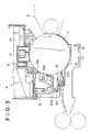
- Fig. 1 and Fig. 3 show an example of the embodiment of the invention.
- Fig. 3 is a view of a portion of an image producing apparatus in which aforesaid mechanical device is incorporated.
- the separating device is incorporated in the photoreceptor module A which is a part of image producing mechanism and is constructed so as to be attached to or detached from the image producing apparatus.
- 11 is a photoreceptor drum which rotates in the arrowed direction.
- 12 is an exposure device which discharges the charge remained on the photoreceptor surface prior to the charging in the start of the process, 13 is the charger.
- 14 is a discharging device which eliminates the charge presented outside of image area.
- 15 is a cleaning device wherein cleaning blade 15A which contacts with the photoreceptor surface and toner guide roller 15B which is rotated as a follower to the rotation of the photoreceptor are incorporated.
- 20 is a separating device for transfer material which is equipped in the lower part of the cleaning device so as to face the photoreceptor surface.
- Fig. 1 and Fig. 2 show the mechanical construction of the separating device 20 wherein each part is assembled on a cover member 20A made of a plate like material to structure a module.
- 21 is a photo-electric sensor detecting toner density of standard sample image made on the photoreceptor surface by reflection density measuring method.
- the toner feeding to the developing device B is controlled by the detected data gained in the photo-electric sensor.
- each of the claws is consisted of three parts, that is, claw tip 22C, pivot 22B for rotation at its central part and balance weight 22A at one end of the claw.
- Aforesaid pivot 22B of the separating claw 22 is supported by supporting member 23 fixed at the cover member 20A to rotate freely counterclockwise by the balance weight 22A provided at the end of the claw.
- a rotatable lever 24 is fixed to the left side of the cover member 20A with a screw 25 which has a step-shaped head in order to rotate on its center and is forced to rotate clockwise by a spring 26. And, a bended portion 24A of the rotatable lever 24 tightly holds one end of a wire, which is explained later, by clamping the wire inserted through a hole provided at the top of the bended portion 24A.
- S is a plunger type solenoid activated by the electricity from the main frame.
- the top of the plunger P is connected to the other end of the rotatable lever 24 to make the lever rotate freely on the pivot 25.
- 27 is a wire fixing part set up at the riht side of the cover member 20A and is fixed to it with a screw 28 after adjusting its position moving the hole of the part along with a pin provided on the cover member.
- the wire fixing part 27 also has a bended portion 27A to which the another end of the wire is clamped to hold the wire tightly after inserted through a hole just as explained before.
- W is aforesaid wire for which thin metal wire having good flexibility or thin plastic resin wire having no deforming characteristic for elongating or shrinking to its length can be used.
- Aforesaid wire is inserted through a small hole provided at the weight 22A fixed to the one end of the claw 22; and one end of wire is fixed to the top of the bended protion 24A of the lotatable lever 24 and the another end of the wire is fixed to the top of the bended portion 27A of the fixing part 27.
- Power switching of the solenoid S is performed by a timer which starts in accordance with the start of the feeding roller or by a signal from a sensor which detects the leading edge of a transfer material coming to the separating site.
- solenoid S is switched off and returned back to the position shown in Fig. 1.
- the present invention using wire, instead of ordinary releasing mechanism which uses sliding member or rotating member, can reduce load to the solenoid, solenoid capacity and space needed to be fixed.
- the contacting or releasing of the claw to the photoreceptor surface can be attained very effectively with a very simple device. Resultingly, a long life separating device for transfer material, which can avoid the needless sliding by the claw on the photoreceptor surface and the toner drop resulted from the sliding of the claw, has been proposed.
Landscapes
- Physics & Mathematics (AREA)
- General Physics & Mathematics (AREA)
- Electrostatic Charge, Transfer And Separation In Electrography (AREA)
Applications Claiming Priority (2)
| Application Number | Priority Date | Filing Date | Title |
|---|---|---|---|
| JP254304/88 | 1988-10-07 | ||
| JP63254304A JP2652682B2 (ja) | 1988-10-07 | 1988-10-07 | 転写材分離装置 |
Publications (3)
| Publication Number | Publication Date |
|---|---|
| EP0363129A2 true EP0363129A2 (de) | 1990-04-11 |
| EP0363129A3 EP0363129A3 (en) | 1990-08-01 |
| EP0363129B1 EP0363129B1 (de) | 1993-12-15 |
Family
ID=17263130
Family Applications (1)
| Application Number | Title | Priority Date | Filing Date |
|---|---|---|---|
| EP89310064A Expired - Lifetime EP0363129B1 (de) | 1988-10-07 | 1989-10-02 | Ablösevorrichtung für Übertragungsmaterial |
Country Status (4)
| Country | Link |
|---|---|
| US (1) | US5006905A (de) |
| EP (1) | EP0363129B1 (de) |
| JP (1) | JP2652682B2 (de) |
| DE (1) | DE68911459T2 (de) |
Cited By (2)
| Publication number | Priority date | Publication date | Assignee | Title |
|---|---|---|---|---|
| US5589925A (en) * | 1994-11-08 | 1996-12-31 | Eastman Kodak Company | Anti-gouging skive mechanism with replaceable fingers |
| EP2138902A3 (de) * | 2008-05-16 | 2014-04-02 | Konica Minolta Business Technologies, Inc. | Bilderzeugungsvorrichtung |
Families Citing this family (4)
| Publication number | Priority date | Publication date | Assignee | Title |
|---|---|---|---|---|
| JP2004170905A (ja) * | 2002-10-29 | 2004-06-17 | Sharp Corp | 用紙剥離機構およびプロセスカートリッジ |
| FI20065310A0 (fi) * | 2006-05-10 | 2006-05-10 | Abb Oy | Ilmankuivain tuulivoimalalaitoksessa |
| JP5178435B2 (ja) * | 2008-10-01 | 2013-04-10 | キヤノン株式会社 | 画像形成装置 |
| JP2020154203A (ja) * | 2019-03-22 | 2020-09-24 | 富士ゼロックス株式会社 | 剥離装置及び画像形成装置 |
Family Cites Families (7)
| Publication number | Priority date | Publication date | Assignee | Title |
|---|---|---|---|---|
| US3955889A (en) * | 1973-12-20 | 1976-05-11 | Katsuragawa Denki Kabushiki Kaisha | Apparatus for stripping receptor papers for use in electrophotographic machines |
| US4261560A (en) * | 1977-12-21 | 1981-04-14 | Ricoh Company, Ltd. | Sheet separation apparatus |
| JPS54153241U (de) * | 1978-04-15 | 1979-10-24 | ||
| JPS56162769A (en) * | 1980-05-20 | 1981-12-14 | Fuji Xerox Co Ltd | Transfer member stripper in electrophotographic copier |
| JPS5929281A (ja) * | 1982-08-12 | 1984-02-16 | Ricoh Co Ltd | 転写材剥離装置 |
| JPS5994772A (ja) * | 1982-11-22 | 1984-05-31 | Ricoh Co Ltd | 乾式定着装置 |
| US4748473A (en) * | 1985-10-21 | 1988-05-31 | Rank Xerox Limited | Printing apparatus with detack device |
-
1988
- 1988-10-07 JP JP63254304A patent/JP2652682B2/ja not_active Expired - Lifetime
-
1989
- 1989-09-28 US US07/413,847 patent/US5006905A/en not_active Expired - Fee Related
- 1989-10-02 DE DE68911459T patent/DE68911459T2/de not_active Expired - Fee Related
- 1989-10-02 EP EP89310064A patent/EP0363129B1/de not_active Expired - Lifetime
Cited By (2)
| Publication number | Priority date | Publication date | Assignee | Title |
|---|---|---|---|---|
| US5589925A (en) * | 1994-11-08 | 1996-12-31 | Eastman Kodak Company | Anti-gouging skive mechanism with replaceable fingers |
| EP2138902A3 (de) * | 2008-05-16 | 2014-04-02 | Konica Minolta Business Technologies, Inc. | Bilderzeugungsvorrichtung |
Also Published As
| Publication number | Publication date |
|---|---|
| US5006905A (en) | 1991-04-09 |
| JPH02100075A (ja) | 1990-04-12 |
| EP0363129A3 (en) | 1990-08-01 |
| DE68911459D1 (de) | 1994-01-27 |
| DE68911459T2 (de) | 1994-05-19 |
| JP2652682B2 (ja) | 1997-09-10 |
| EP0363129B1 (de) | 1993-12-15 |
Similar Documents
| Publication | Publication Date | Title |
|---|---|---|
| US5262827A (en) | Light emitting diode printer | |
| JPH0240569B2 (de) | ||
| CA1088143A (en) | Reader-printer apparatus | |
| US5006905A (en) | Separating apparatus of transfer material | |
| US4443101A (en) | Recording paper separation failure release for copying machine | |
| EP0177039B1 (de) | Elektrostatisches Kopiergerät | |
| US5564337A (en) | Plate clamping apparatus of printing machine | |
| US4954847A (en) | Recirculating automatic document feeder | |
| US5024431A (en) | Sheet transport device with easy sheet jam handling | |
| US5546171A (en) | Displaceable transfer apparatus having a post-transfer guide | |
| US5805957A (en) | Image forming apparatus | |
| US4766459A (en) | Apparatus for separating transfer paper from photosensitive member of copying machine | |
| KR870000893Y1 (ko) | 복사기의 잼 검지 및 그 제거장치 | |
| JP2726901B2 (ja) | 給紙装置 | |
| JPH073416Y2 (ja) | 画像形成装置の用紙分離装置 | |
| JP2001088981A (ja) | 原稿搬送装置 | |
| JP3251819B2 (ja) | 原稿搬送装置 | |
| JP3286403B2 (ja) | 画像形成装置 | |
| JPH08101544A (ja) | 画像形成装置 | |
| JP2719590B2 (ja) | 給紙装置 | |
| JP2656322B2 (ja) | 自動原稿送り装置 | |
| KR100202381B1 (ko) | 전자사진 프로세서의 기록용지 급지 장치 | |
| JP2511579Y2 (ja) | 画像形成装置における給紙装置 | |
| JPH03288735A (ja) | 自動給紙装置 | |
| JPH09251250A (ja) | 画像形成装置 |
Legal Events
| Date | Code | Title | Description |
|---|---|---|---|
| PUAI | Public reference made under article 153(3) epc to a published international application that has entered the european phase |
Free format text: ORIGINAL CODE: 0009012 |
|
| AK | Designated contracting states |
Kind code of ref document: A2 Designated state(s): DE GB |
|
| PUAL | Search report despatched |
Free format text: ORIGINAL CODE: 0009013 |
|
| AK | Designated contracting states |
Kind code of ref document: A3 Designated state(s): DE GB |
|
| 17P | Request for examination filed |
Effective date: 19901213 |
|
| 17Q | First examination report despatched |
Effective date: 19920612 |
|
| GRAA | (expected) grant |
Free format text: ORIGINAL CODE: 0009210 |
|
| AK | Designated contracting states |
Kind code of ref document: B1 Designated state(s): DE GB |
|
| REF | Corresponds to: |
Ref document number: 68911459 Country of ref document: DE Date of ref document: 19940127 |
|
| PLBE | No opposition filed within time limit |
Free format text: ORIGINAL CODE: 0009261 |
|
| STAA | Information on the status of an ep patent application or granted ep patent |
Free format text: STATUS: NO OPPOSITION FILED WITHIN TIME LIMIT |
|
| 26N | No opposition filed | ||
| PGFP | Annual fee paid to national office [announced via postgrant information from national office to epo] |
Ref country code: GB Payment date: 19960923 Year of fee payment: 8 |
|
| PGFP | Annual fee paid to national office [announced via postgrant information from national office to epo] |
Ref country code: DE Payment date: 19961011 Year of fee payment: 8 |
|
| PG25 | Lapsed in a contracting state [announced via postgrant information from national office to epo] |
Ref country code: GB Free format text: LAPSE BECAUSE OF NON-PAYMENT OF DUE FEES Effective date: 19971002 |
|
| GBPC | Gb: european patent ceased through non-payment of renewal fee |
Effective date: 19971002 |
|
| PG25 | Lapsed in a contracting state [announced via postgrant information from national office to epo] |
Ref country code: DE Free format text: LAPSE BECAUSE OF NON-PAYMENT OF DUE FEES Effective date: 19980701 |