EP0363131A1 - Pneumatisches Einführverfahren mittels Drossel für eine Faser - Google Patents
Pneumatisches Einführverfahren mittels Drossel für eine Faser Download PDFInfo
- Publication number
- EP0363131A1 EP0363131A1 EP89310068A EP89310068A EP0363131A1 EP 0363131 A1 EP0363131 A1 EP 0363131A1 EP 89310068 A EP89310068 A EP 89310068A EP 89310068 A EP89310068 A EP 89310068A EP 0363131 A1 EP0363131 A1 EP 0363131A1
- Authority
- EP
- European Patent Office
- Prior art keywords
- passageway
- fibre
- fluid flow
- package
- fibre package
- Prior art date
- Legal status (The legal status is an assumption and is not a legal conclusion. Google has not performed a legal analysis and makes no representation as to the accuracy of the status listed.)
- Granted
Links
Images

Classifications
-
- G—PHYSICS
- G02—OPTICS
- G02B—OPTICAL ELEMENTS, SYSTEMS OR APPARATUS
- G02B6/00—Light guides; Structural details of arrangements comprising light guides and other optical elements, e.g. couplings
- G02B6/44—Mechanical structures for providing tensile strength and external protection for fibres, e.g. optical transmission cables
- G02B6/4479—Manufacturing methods of optical cables
- G02B6/4485—Installing in protective tubing by fluid drag during manufacturing
-
- B—PERFORMING OPERATIONS; TRANSPORTING
- B65—CONVEYING; PACKING; STORING; HANDLING THIN OR FILAMENTARY MATERIAL
- B65H—HANDLING THIN OR FILAMENTARY MATERIAL, e.g. SHEETS, WEBS, CABLES
- B65H59/00—Adjusting or controlling tension in filamentary material, e.g. for preventing snarling; Applications of tension indicators
- B65H59/10—Adjusting or controlling tension in filamentary material, e.g. for preventing snarling; Applications of tension indicators by devices acting on running material and not associated with supply or take-up devices
- B65H59/105—Adjusting or controlling tension in filamentary material, e.g. for preventing snarling; Applications of tension indicators by devices acting on running material and not associated with supply or take-up devices the material being subjected to the action of a fluid
-
- B—PERFORMING OPERATIONS; TRANSPORTING
- B65—CONVEYING; PACKING; STORING; HANDLING THIN OR FILAMENTARY MATERIAL
- B65H—HANDLING THIN OR FILAMENTARY MATERIAL, e.g. SHEETS, WEBS, CABLES
- B65H2701/00—Handled material; Storage means
- B65H2701/30—Handled filamentary material
- B65H2701/31—Textiles threads or artificial strands of filaments
Definitions
- This invention relates to fibre blowing.
- Fibre blowing is a process in which lightweight transmission lines are advanced through installation ducts by the viscous drag of a fluid, usually compressed air. This process is described in our European patent specification 108590.
- a known form of fibre blowing apparatus includes a transmission line package coiled into a sealed, pressurised container, the pressure within the container providing the propellant gas, thus eliminating the need for a compressor or other seperate source of propellant.
- Such pressurised containers may be particularly useful for repair work.
- a disadvantage of such an arrangement is that, once the pressure in the container is released to commence installation of a transmission line package into a duct, the propellant cannot be shut off without a substantial risk of that portion of the package which is already in the duct being damaged by closure of a valve to block the duct. This is particularly a problem where the package contains delicate transmission lines such as optical fibres. Also, the package travelling along the duct has a significant momentum, and, if abruptly halted, the tension induced at the halting point may be harmful.
- a further problem that may be experienced in the pressurised container method of fibre blowing is that the initial pressure may be very much greater than that necessaryy to ensure that there is sufficient propellant to ensure that all the package in the container can be installed.
- the aim of the invention is to provide apparatus for selectively inhibiting the flow of fluid from a pressurised container of fibre package, and for inhibiting or retarding the advance of the fibre package.
- the present invention provides apparatus for inhibiting fluid flow and fibre package motion in a fibre blowing operation, the apparatus comprising a passageway along which a fibre package and fluid flow can be passed, a first junction at which the fibre package and at least part of the fluid flow can separate along, respectively, a fibre package passageway and a fluid flow passageway, a second junction at which the fibre package passageway and the fluid flow passageway recombine, a valve disposed in the fluid flow passageway between the first and second junctions for selectively blocking the fluid flow along the fluid flow passageway, and a flexible sealing member for sealing against the fibre to inhibit fluid flow along the fibre passageway.
- the fluid flow passageway is separated from the fibre passageway by an elastic, flexible membrane located between the first and second junctions and preceding the valve, the arrangement being such that, upon closure of the valve, pressure in the fluid flow passageway expands the membrane into the fibre package passageway.
- fibre package means any line or filament capable of installation by the fibre blowing technique, and is not necessarily restricted to optical fibres.
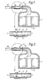
- Figure 1 shows a container 1 having a central annulus 2 about which a coil of fibre package 3 is wound.
- the fibre package 3 may comprise, for example, one or more optical fibres enclosed in a lightweight protective covering.
- the fibre package 3 is threaded through a funnel portion 4 on the container 1, and into a braking section 5.
- the braking section 5 is divided into a double passageway 7, 8 by a dividing wall 6.
- the fibre package 3 is diverted into the passageway 7, and the other passageway 8 is provided with a valve 9.
- the container 1 is capable of being sealed and maintained under pressure by closing the brake valve 9 to operate a sealing mechanism described hereinafter.
- a separate port (not shown) for pressurising the container 1 may be provided.
- the container 1 may be pressurised through the braking section 5 with the valve 9 open, the valve 9 then being closed before the pressurising source is disconnected.
- the free end of the fibre package 3 may be taped or clipped to the outermost end of the braking section 5 to prevent unthreading.
- An installation duct 10 is connected to the outermost end of the braking section 5.
- the outermost end of the braking section 5 would generally be cleared, prior to connection of the container 1 to the installation duct 10, thereby eliminating any damage caused due to securing or exposure.
- the valve 9 is opened to the configuration shown in Figure 1. Pressurised gas then commences escaping from the container 1 along the passageways 7 and 8 and into the duct 10, the pressurised gas propelling the fibre package 3 along the duct.
- Various techniques may be employed to aid insertion of the free end of the fibre package 3 into the duct 10.
- a length of the fibre package 3 released from the container 1, prior to connection of the duct may be manually inserted.
- the duct 10 (or a connection tube) may be vented a short distance away from the container 1, in order to create a high local flow and draw the free end of the fibre package 3 into the duct.
- valve 9 When it is desired to cease the installation process, the valve 9 is closed. At this point, there is still a route for propellant along the passageway 7, although this passageway is insufficient to provide a substantive alternative route for the air.
- a part of the wall 6 between the passageways 7 and 8 is made of a membrane 11 of flexible, elastic material such as a soft grade of rubber. As pressure builds up in the now closed off passageway 8, the membrane 11 balloons outwardly into the passageway 7, and commences pressing against the fibre package 3 and the walls of passageway 7.
- the sizes of the membrane 11 and the pasageways 7 and 8 are such that, at the operating pressures of the container 1, the membrane 11 completely closes off the passageway 7.
- passageway 7 is drawn on an enlarged scale for clarity: in fact it should only be sufficiently wide for the passage of the fibre package 3, and thus very little air flow is required to enable closure by the flexible membrane 11.
- the passageway 8 is much larger, thereby permitting a high air flow with little pressure differential.
- the structure of the passageways 7 and 8 may comprise two side-by-side tubes with a common wall portion, the common wall portion having three longitudinally-spaced ports (not shown), the two end ports being for diversion of the fibre package 3, and the central port being for supporting the flexible membrane 11.
- the fibre diversion tube (the passageway 7) may be made smaller than the other tube (the passageway 8).
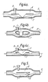
- An equivalent arrangement may be made by a single tube having an internal partition (see Figure 3a), by a branched structure (see Figure 3b), or by a diversion path for the propellant (see Figure 3c) leaving a straight, through-path for the fibre package 3. This last-mentioned arrangement is particularly preferable.
- the general structure is the same, namely two passageways with communicating entry and exit ports, and an intermediate port blocked by a membrane.
- the fibre package 3 passes along one route, the other route being blocked by the valve 9.
- Figures 4a, 4b and 4c show the same arrangements with the fibre package 3 braked.
- Another alternative to the embodiments shown in Figures 1 to 4 is to eliminate the port with the flexible membrane, and to locate a pressure-sensitive seal 12 (see Figure 5) around the entry port to the fibre passageway 7. Under flow conditions, the seal 12 lightly rests against the fibre package 3, but, as soon as pressure builds up above a predetermined level in the propellant passageway 8, the seal is urged tightly around the fibre package 3, preventing further movement or escape of propellant into the passageway 8.
- the restriction caused by the seal 12 results in the main flow of propellant being along the passageway 8, and the section of the fibre package 3 within the fibre passageway 7 is not subjected to viscous drag.
- the length of the fibre package 3 within the passageway 7 is not sufficient to influence the installation significantly.
Landscapes
- Physics & Mathematics (AREA)
- Engineering & Computer Science (AREA)
- Manufacturing & Machinery (AREA)
- General Physics & Mathematics (AREA)
- Optics & Photonics (AREA)
- Filling Or Discharging Of Gas Storage Vessels (AREA)
- Braking Arrangements (AREA)
- Separation Using Semi-Permeable Membranes (AREA)
- Light Guides In General And Applications Therefor (AREA)
- Electric Cable Installation (AREA)
- Yarns And Mechanical Finishing Of Yarns Or Ropes (AREA)
- Multicomponent Fibers (AREA)
Priority Applications (1)
| Application Number | Priority Date | Filing Date | Title |
|---|---|---|---|
| AT89310068T ATE101281T1 (de) | 1988-10-05 | 1989-10-02 | Pneumatisches einfuehrverfahren mittels drossel fuer eine faser. |
Applications Claiming Priority (2)
| Application Number | Priority Date | Filing Date | Title |
|---|---|---|---|
| GB8823426 | 1988-10-05 | ||
| GB888823426A GB8823426D0 (en) | 1988-10-05 | 1988-10-05 | Fibre blowing brake |
Publications (2)
| Publication Number | Publication Date |
|---|---|
| EP0363131A1 true EP0363131A1 (de) | 1990-04-11 |
| EP0363131B1 EP0363131B1 (de) | 1994-02-02 |
Family
ID=10644773
Family Applications (1)
| Application Number | Title | Priority Date | Filing Date |
|---|---|---|---|
| EP89310068A Expired - Lifetime EP0363131B1 (de) | 1988-10-05 | 1989-10-02 | Pneumatisches Einführverfahren mittels Drossel für eine Faser |
Country Status (14)
| Country | Link |
|---|---|
| US (1) | US5165662A (de) |
| EP (1) | EP0363131B1 (de) |
| JP (1) | JP2823621B2 (de) |
| AT (1) | ATE101281T1 (de) |
| AU (1) | AU629863B2 (de) |
| CA (1) | CA2000067C (de) |
| DE (1) | DE68912868T2 (de) |
| DK (1) | DK59391A (de) |
| ES (1) | ES2048293T3 (de) |
| GB (1) | GB8823426D0 (de) |
| HK (1) | HK136296A (de) |
| IE (1) | IE62819B1 (de) |
| NZ (1) | NZ230891A (de) |
| WO (1) | WO1990004191A1 (de) |
Cited By (1)
| Publication number | Priority date | Publication date | Assignee | Title |
|---|---|---|---|---|
| CN103757807A (zh) * | 2013-12-31 | 2014-04-30 | 吴江市豪辉布业有限公司 | 导纱器 |
Families Citing this family (5)
| Publication number | Priority date | Publication date | Assignee | Title |
|---|---|---|---|---|
| US3685824A (en) * | 1971-03-10 | 1972-08-22 | Three Line Research And Dev Co | Training hurdle |
| GB8714578D0 (en) * | 1987-06-22 | 1987-07-29 | British Telecomm | Fibre winding |
| US5813658A (en) * | 1994-11-23 | 1998-09-29 | Arnco Corporation | Cable feeding apparatus |
| US6012621A (en) | 1997-09-04 | 2000-01-11 | Condux International, Inc. | Cable conveying apparatus |
| US6511047B1 (en) | 1999-12-15 | 2003-01-28 | Newport News Shipbuilding And Dry Dock Company | Apparatus for making a plurality of blown optical fiber insertions into a duct |
Citations (5)
| Publication number | Priority date | Publication date | Assignee | Title |
|---|---|---|---|---|
| GB1262772A (en) * | 1968-03-27 | 1972-02-09 | Robertshaw Controls Co | Fluid flow control systems |
| US4206860A (en) * | 1978-12-18 | 1980-06-10 | Eastman Kodak Company | Air dissipator apparatus for airjet tow puddling |
| EP0108590A1 (de) * | 1982-11-08 | 1984-05-16 | BRITISH TELECOMMUNICATIONS public limited company | Optische Übertragungsfasern |
| DE3409376A1 (de) * | 1984-03-14 | 1985-12-05 | Siemens AG, 1000 Berlin und 8000 München | Verfahren zur geschwindigkeitsdosierung einer laengsbewegten faser, sowie vorrichtung zur durchfuehrung des verfahrens |
| EP0253636A1 (de) * | 1986-07-16 | 1988-01-20 | BRITISH TELECOMMUNICATIONS public limited company | Verfahren und Einrichtung zur Abstimmung |
Family Cites Families (5)
| Publication number | Priority date | Publication date | Assignee | Title |
|---|---|---|---|---|
| US2515953A (en) * | 1947-01-08 | 1950-07-18 | Dufresne Joseph Eugene | Rodding machine |
| US3533599A (en) * | 1969-09-10 | 1970-10-13 | Holub Ind Inc | Fish tape winder |
| GB8706803D0 (en) | 1987-03-23 | 1987-04-29 | British Telecomm | Optical fibre installation |
| NL193126B (nl) * | 1987-04-28 | 1998-07-01 | Nederland Ptt | Werkwijze en inrichting voor het aanbrengen van een kabel in een kabelgeleidingsbuis. |
| CA1306241C (en) * | 1988-08-11 | 1992-08-11 | Nobuo Araki | Method and apparatus for inserting thread into tube |
-
1988
- 1988-10-05 GB GB888823426A patent/GB8823426D0/en active Pending
-
1989
- 1989-10-02 CA CA002000067A patent/CA2000067C/en not_active Expired - Lifetime
- 1989-10-02 US US07/681,537 patent/US5165662A/en not_active Expired - Lifetime
- 1989-10-02 JP JP1510319A patent/JP2823621B2/ja not_active Expired - Fee Related
- 1989-10-02 AT AT89310068T patent/ATE101281T1/de active
- 1989-10-02 ES ES89310068T patent/ES2048293T3/es not_active Expired - Lifetime
- 1989-10-02 AU AU43318/89A patent/AU629863B2/en not_active Ceased
- 1989-10-02 EP EP89310068A patent/EP0363131B1/de not_active Expired - Lifetime
- 1989-10-02 DE DE68912868T patent/DE68912868T2/de not_active Expired - Fee Related
- 1989-10-02 WO PCT/GB1989/001165 patent/WO1990004191A1/en not_active Ceased
- 1989-10-04 IE IE316989A patent/IE62819B1/en not_active IP Right Cessation
- 1989-10-04 NZ NZ230891A patent/NZ230891A/en unknown
-
1991
- 1991-04-03 DK DK059391A patent/DK59391A/da not_active Application Discontinuation
-
1996
- 1996-07-25 HK HK136296A patent/HK136296A/en not_active IP Right Cessation
Patent Citations (5)
| Publication number | Priority date | Publication date | Assignee | Title |
|---|---|---|---|---|
| GB1262772A (en) * | 1968-03-27 | 1972-02-09 | Robertshaw Controls Co | Fluid flow control systems |
| US4206860A (en) * | 1978-12-18 | 1980-06-10 | Eastman Kodak Company | Air dissipator apparatus for airjet tow puddling |
| EP0108590A1 (de) * | 1982-11-08 | 1984-05-16 | BRITISH TELECOMMUNICATIONS public limited company | Optische Übertragungsfasern |
| DE3409376A1 (de) * | 1984-03-14 | 1985-12-05 | Siemens AG, 1000 Berlin und 8000 München | Verfahren zur geschwindigkeitsdosierung einer laengsbewegten faser, sowie vorrichtung zur durchfuehrung des verfahrens |
| EP0253636A1 (de) * | 1986-07-16 | 1988-01-20 | BRITISH TELECOMMUNICATIONS public limited company | Verfahren und Einrichtung zur Abstimmung |
Cited By (1)
| Publication number | Priority date | Publication date | Assignee | Title |
|---|---|---|---|---|
| CN103757807A (zh) * | 2013-12-31 | 2014-04-30 | 吴江市豪辉布业有限公司 | 导纱器 |
Also Published As
| Publication number | Publication date |
|---|---|
| DE68912868T2 (de) | 1994-05-19 |
| ATE101281T1 (de) | 1994-02-15 |
| DE68912868D1 (de) | 1994-03-17 |
| CA2000067C (en) | 1999-08-31 |
| AU629863B2 (en) | 1992-10-15 |
| IE893169L (en) | 1990-04-05 |
| HK136296A (en) | 1996-08-02 |
| JPH04500866A (ja) | 1992-02-13 |
| JP2823621B2 (ja) | 1998-11-11 |
| NZ230891A (en) | 1992-04-28 |
| IE62819B1 (en) | 1995-03-08 |
| EP0363131B1 (de) | 1994-02-02 |
| US5165662A (en) | 1992-11-24 |
| GB8823426D0 (en) | 1988-11-09 |
| WO1990004191A1 (en) | 1990-04-19 |
| DK59391D0 (da) | 1991-04-03 |
| CA2000067A1 (en) | 1990-04-05 |
| ES2048293T3 (es) | 1994-03-16 |
| AU4331889A (en) | 1990-05-01 |
| DK59391A (da) | 1991-04-03 |
Similar Documents
| Publication | Publication Date | Title |
|---|---|---|
| EP0323028B1 (de) | Verfahren und Vorrichtung zum pneumatischen Installieren eines faseroptischen Körpers | |
| CA1282052C (en) | Method and device for introducing a cable into a cable guide tube | |
| US5897103A (en) | Method for installing cables | |
| JP2896400B2 (ja) | 伝送線の布設方法および装置 | |
| US5143353A (en) | Method for laying optical fiber unit and apparatus therefor | |
| ES2269068T3 (es) | Procedimiento de instalacion de un cable en un conducto. | |
| EP0363131B1 (de) | Pneumatisches Einführverfahren mittels Drossel für eine Faser | |
| JPH03504770A (ja) | 伝送線の布設 | |
| CA2159635A1 (en) | Fluid-conducting swivel and method | |
| US5127630A (en) | Method for drawing cables into a pipe | |
| US20040079929A1 (en) | Pipe threading | |
| US5038990A (en) | Pneumatic shoe for high speed filamentary capstan | |
| EP0901593B1 (de) | Rohrverbinder für röhren in denen eine kabelinstallation vorgesehen ist | |
| ES2033595T3 (es) | Dispositivo de eyeccion hidraulica por empujadores con sistema de restitucion neumatica. | |
| US3910523A (en) | Arrangement for pneumatic piping of cargoes in containers | |
| CN215061268U (zh) | 一种具有缓冲系统的气体充装装置 | |
| JP2000308225A (ja) | ダクト中にチューブを敷設する方法及び敷設中のチューブに圧力を持たせるための装置 | |
| GB2304840A (en) | Vacuum bleeding equipment | |
| EP0396680B1 (de) | Pneumatischer schuh für schnellgeschwindigkeitsfadenwinde | |
| JPH04114110A (ja) | 線条体の管路内通線方法 | |
| JPH01303227A (ja) | 気送式管体検査用カプセルの定速制御方法 |
Legal Events
| Date | Code | Title | Description |
|---|---|---|---|
| PUAI | Public reference made under article 153(3) epc to a published international application that has entered the european phase |
Free format text: ORIGINAL CODE: 0009012 |
|
| AK | Designated contracting states |
Kind code of ref document: A1 Designated state(s): AT BE CH DE ES FR GB GR IT LI LU NL SE |
|
| 17P | Request for examination filed |
Effective date: 19900924 |
|
| 17Q | First examination report despatched |
Effective date: 19920309 |
|
| GRAA | (expected) grant |
Free format text: ORIGINAL CODE: 0009210 |
|
| AK | Designated contracting states |
Kind code of ref document: B1 Designated state(s): AT BE CH DE ES FR GB GR IT LI LU NL SE |
|
| REF | Corresponds to: |
Ref document number: 101281 Country of ref document: AT Date of ref document: 19940215 Kind code of ref document: T |
|
| ITF | It: translation for a ep patent filed | ||
| REG | Reference to a national code |
Ref country code: ES Ref legal event code: FG2A Ref document number: 2048293 Country of ref document: ES Kind code of ref document: T3 |
|
| REF | Corresponds to: |
Ref document number: 68912868 Country of ref document: DE Date of ref document: 19940317 |
|
| ET | Fr: translation filed | ||
| REG | Reference to a national code |
Ref country code: GR Ref legal event code: FG4A Free format text: 3011522 |
|
| PLBE | No opposition filed within time limit |
Free format text: ORIGINAL CODE: 0009261 |
|
| STAA | Information on the status of an ep patent application or granted ep patent |
Free format text: STATUS: NO OPPOSITION FILED WITHIN TIME LIMIT |
|
| 26N | No opposition filed | ||
| EAL | Se: european patent in force in sweden |
Ref document number: 89310068.5 |
|
| PGFP | Annual fee paid to national office [announced via postgrant information from national office to epo] |
Ref country code: AT Payment date: 19970916 Year of fee payment: 9 Ref country code: BE Payment date: 19970916 Year of fee payment: 9 |
|
| PGFP | Annual fee paid to national office [announced via postgrant information from national office to epo] |
Ref country code: SE Payment date: 19970918 Year of fee payment: 9 |
|
| PGFP | Annual fee paid to national office [announced via postgrant information from national office to epo] |
Ref country code: GR Payment date: 19970926 Year of fee payment: 9 |
|
| PGFP | Annual fee paid to national office [announced via postgrant information from national office to epo] |
Ref country code: LU Payment date: 19971006 Year of fee payment: 9 |
|
| PGFP | Annual fee paid to national office [announced via postgrant information from national office to epo] |
Ref country code: ES Payment date: 19971008 Year of fee payment: 9 |
|
| PG25 | Lapsed in a contracting state [announced via postgrant information from national office to epo] |
Ref country code: AT Free format text: LAPSE BECAUSE OF NON-PAYMENT OF DUE FEES Effective date: 19981002 Ref country code: LU Free format text: LAPSE BECAUSE OF NON-PAYMENT OF DUE FEES Effective date: 19981002 |
|
| PG25 | Lapsed in a contracting state [announced via postgrant information from national office to epo] |
Ref country code: SE Free format text: LAPSE BECAUSE OF NON-PAYMENT OF DUE FEES Effective date: 19981003 Ref country code: ES Free format text: LAPSE BECAUSE OF THE APPLICANT RENOUNCES Effective date: 19981003 |
|
| PG25 | Lapsed in a contracting state [announced via postgrant information from national office to epo] |
Ref country code: GR Free format text: LAPSE BECAUSE OF NON-PAYMENT OF DUE FEES Effective date: 19981031 Ref country code: BE Free format text: LAPSE BECAUSE OF NON-PAYMENT OF DUE FEES Effective date: 19981031 |
|
| BERE | Be: lapsed |
Owner name: BRITISH TELECOMMUNICATIONS P.L.C. Effective date: 19981031 |
|
| EUG | Se: european patent has lapsed |
Ref document number: 89310068.5 |
|
| REG | Reference to a national code |
Ref country code: ES Ref legal event code: FD2A Effective date: 20001009 |
|
| PGFP | Annual fee paid to national office [announced via postgrant information from national office to epo] |
Ref country code: CH Payment date: 20010919 Year of fee payment: 13 |
|
| REG | Reference to a national code |
Ref country code: GB Ref legal event code: IF02 |
|
| PG25 | Lapsed in a contracting state [announced via postgrant information from national office to epo] |
Ref country code: LI Free format text: LAPSE BECAUSE OF NON-PAYMENT OF DUE FEES Effective date: 20021031 Ref country code: CH Free format text: LAPSE BECAUSE OF NON-PAYMENT OF DUE FEES Effective date: 20021031 |
|
| REG | Reference to a national code |
Ref country code: CH Ref legal event code: PL |
|
| PG25 | Lapsed in a contracting state [announced via postgrant information from national office to epo] |
Ref country code: IT Free format text: LAPSE BECAUSE OF NON-PAYMENT OF DUE FEES Effective date: 20051002 |
|
| PGFP | Annual fee paid to national office [announced via postgrant information from national office to epo] |
Ref country code: GB Payment date: 20070921 Year of fee payment: 19 |
|
| PGFP | Annual fee paid to national office [announced via postgrant information from national office to epo] |
Ref country code: DE Payment date: 20070921 Year of fee payment: 19 Ref country code: NL Payment date: 20070913 Year of fee payment: 19 |
|
| PGFP | Annual fee paid to national office [announced via postgrant information from national office to epo] |
Ref country code: FR Payment date: 20070912 Year of fee payment: 19 |
|
| GBPC | Gb: european patent ceased through non-payment of renewal fee |
Effective date: 20081002 |
|
| NLV4 | Nl: lapsed or anulled due to non-payment of the annual fee |
Effective date: 20090501 |
|
| REG | Reference to a national code |
Ref country code: FR Ref legal event code: ST Effective date: 20090630 |
|
| PG25 | Lapsed in a contracting state [announced via postgrant information from national office to epo] |
Ref country code: NL Free format text: LAPSE BECAUSE OF NON-PAYMENT OF DUE FEES Effective date: 20090501 |
|
| PG25 | Lapsed in a contracting state [announced via postgrant information from national office to epo] |
Ref country code: DE Free format text: LAPSE BECAUSE OF NON-PAYMENT OF DUE FEES Effective date: 20090501 |
|
| PG25 | Lapsed in a contracting state [announced via postgrant information from national office to epo] |
Ref country code: FR Free format text: LAPSE BECAUSE OF NON-PAYMENT OF DUE FEES Effective date: 20081031 |
|
| PG25 | Lapsed in a contracting state [announced via postgrant information from national office to epo] |
Ref country code: GB Free format text: LAPSE BECAUSE OF NON-PAYMENT OF DUE FEES Effective date: 20081002 |