EP0363246B1 - Apparatus for placing and withdrawing a plasma arc torch in an installation working under such a pressure and temperature that a direct intervention is impossible - Google Patents
Apparatus for placing and withdrawing a plasma arc torch in an installation working under such a pressure and temperature that a direct intervention is impossible Download PDFInfo
- Publication number
- EP0363246B1 EP0363246B1 EP89402600A EP89402600A EP0363246B1 EP 0363246 B1 EP0363246 B1 EP 0363246B1 EP 89402600 A EP89402600 A EP 89402600A EP 89402600 A EP89402600 A EP 89402600A EP 0363246 B1 EP0363246 B1 EP 0363246B1
- Authority
- EP
- European Patent Office
- Prior art keywords
- torch
- shutter
- pressure
- volume
- tubular member
- Prior art date
- Legal status (The legal status is an assumption and is not a legal conclusion. Google has not performed a legal analysis and makes no representation as to the accuracy of the status listed.)
- Expired - Lifetime
Links
- 238000009434 installation Methods 0.000 title description 6
- 238000000034 method Methods 0.000 claims description 9
- 238000007789 sealing Methods 0.000 claims description 6
- 238000011144 upstream manufacturing Methods 0.000 claims description 5
- 229920001971 elastomer Polymers 0.000 claims description 4
- 239000000806 elastomer Substances 0.000 claims description 3
- 229910052751 metal Inorganic materials 0.000 claims description 3
- 230000000295 complement effect Effects 0.000 claims description 2
- 230000000694 effects Effects 0.000 claims 1
- 235000010599 Verbascum thapsus Nutrition 0.000 description 44
- 230000004048 modification Effects 0.000 description 4
- 238000012986 modification Methods 0.000 description 4
- 239000000243 solution Substances 0.000 description 3
- 244000178289 Verbascum thapsus Species 0.000 description 2
- 238000002347 injection Methods 0.000 description 2
- 239000007924 injection Substances 0.000 description 2
- 239000002184 metal Substances 0.000 description 2
- 238000001816 cooling Methods 0.000 description 1
- 230000001627 detrimental effect Effects 0.000 description 1
- 238000010586 diagram Methods 0.000 description 1
- 230000009931 harmful effect Effects 0.000 description 1
- 238000004519 manufacturing process Methods 0.000 description 1
- 239000003607 modifier Substances 0.000 description 1
- 239000003775 serotonin noradrenalin reuptake inhibitor Substances 0.000 description 1
- 229910001220 stainless steel Inorganic materials 0.000 description 1
- 239000010935 stainless steel Substances 0.000 description 1
Images

Classifications
-
- C—CHEMISTRY; METALLURGY
- C21—METALLURGY OF IRON
- C21B—MANUFACTURE OF IRON OR STEEL
- C21B5/00—Making pig-iron in the blast furnace
- C21B5/001—Injecting additional fuel or reducing agents
- C21B5/002—Heated electrically (plasma)
Definitions
- the present invention relates to a method and a device for placing and removing a plasma torch on an installation operating under high pressure and temperature conditions.
- Plasma torches of the non-transferred arc type, are used in a certain number of installations or apparatuses, the operation of which involves pressures and temperatures which prohibit any direct intervention for the removal of the torch or its setting up .
- the placement or removal of the plasma torch requires a change in the operating regime of the installation or of the apparatus, in particular a momentary reduction in the pressure and possibly working temperature conditions which are detrimental. in every way.
- blast furnaces As a typical example of an installation in which plasma torches are used, mention may be made of blast furnaces and it is in this application that the invention will be described.
- Plasma torches are used on blast furnaces to overheat the hot wind from the cowper before it is injected into the device.
- the injection of the hot wind is carried out by means of a conduit, or nozzle, to which is connected by one end an inclined cuff, for example as described in FR-A-2,566,802 of the applicant, and the nose of the torch is inserted into the opposite end of this cuff.
- This cuff should be as short as possible to reduce heat loss.
- the wind flow in the nozzle must be reduced to a sufficiently low pressure, of the order of about 400 mb or less and, due to the temperature and the slight flow of hot gas, the operation s 'performs under difficult conditions, and results in production losses proportional to the duration of the change of regime of the blast furnace.
- a volume of the nozzle was isolated by means of two valves disposed respectively upstream and downstream of the cuff receiving the nose of the torch, thus making it possible to bring this volume to atmospheric pressure to perform the necessary operations.
- a valve was inserted on a longer cuff, immediately downstream from the nose of the torch, thus making it possible to use a valve of smaller dimensions than the previous ones, but requiring to lengthen the cuff, which increases heat losses at the connection interface and changes the mixing conditions.
- valve as well as the refractory of the cuff are partly exposed to the thermal flow of the plasma, thus requiring it to be cooled effectively by means of expensive devices.
- a short cuff having just the length of the nose of the torch was produced and a valve was inserted in the middle of its length.
- the valve operates in poor conditions with regard to the ⁇ P, which results in deformations that hinder its operation, and leaks.
- this arrangement prevents the valve from being closed when the torch is in place and hot gas leaks when the torch is removed, before the valve closes.
- the invention also relates to a device for implementing the method defined above, characterized in that it comprises, upstream of the valve, an expandable and retractable tubular member fixed in leaktight manner at one end, around the end of the cuff adapted to receive the nose of the torch and by its other end around this nose, means for balancing the pressure in said member with that prevailing downstream of the valve, and means for cooling said tubular member.
- said annular member is fixed around the nose of the torch in a removable manner, additional sealing means being provided on said member and on the torch as well as means for mutual locking of said member on the torch.
- said means for balancing the pressure in said member with that downstream of the valve comprises a conduit connecting the interior of said member to a source of compressed air by means of a pressure reducer- pilot connected to the downstream side of the valve by a tap.
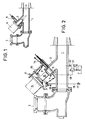
- Figure 1 is a schematic sectional view showing a known arrangement of a plasma torch on a cuff secured to a nozzle for injecting hot wind into a blast furnace.
- Figure 2 is a view similar to that of Figure 1, showing the device according to the invention.
- Figures 3 and 4 are schematic sectional views showing the operation of the device of Figure 1.
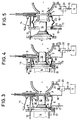
- Figure 5 is a view of a variant.
- Figure 6 is a view of another variant.
- Figure 1 a diagram of a known arrangement in which the reference 1 designates a hot wind injection nozzle in a blast furnace, comprising a wind inlet 2 and an inclined sleeve 3 for the connection of a plasma torch 4, of the non-transferred arc type, this sleeve being provided with a shut-off valve 5 situated approximately in the middle of its length.
- valve operates in poor ⁇ P conditions, which have caused deformations of the valve shutter, resulting in difficulties in operating the valve, leaks and leaks.
- FIG. 2 shows the device according to the invention for implementing the method defined above.
- This device can be adapted to the arrangement of FIG. 1, practically without modification.
- This tubular member 6 may consist for example of metallic annular elements mounted to slide one inside the other in a telescopic and sealed manner, as known per se.
- the tubular member 6 is provided with a sealing collar 8 having in section a suitable shape for fitting tightly around a complementary sealing part 9 of the end of the torch 4 .
- At least one guide rod 10 is provided fixed parallel to the axis of the cuff 3 and on which the flange 8 of the tubular member 6 can slide, as well as a flange 11 of the torch, set back from his nose 12.
- the device also comprises at least one locking member 13 articulated on the edge of the flange 8 so as to be able to come into engagement with the flange 11 of the torch in order to maintain the latter in sealed contact with the flange; at least one other similar locking member 14 is articulated on the cuff 3 and adapted to cooperate outside the tubular member with the flange 11 of the torch, in order to retain the latter in the operating position, as is will describe below.
- conduit 15 connecting the interior of the tubular member 6 to the atmosphere via a tap 17, and another conduit 18 connecting the interior of the member 6 to a source of compressed air S by means of a tap 19 and of a pilot regulator 20 which is itself connected to the interior of the nozzle 1 by a duct 21 and a tap 22.
- FIG. 2 shows the torch 4 in the non-use position, in which the valve 5 is closed and the torch remote from the flange 8.
- valves 17, 19 and 22 are closed and the torch is made to slide on the guide 10 to bring the part 9 in tight contact with the flange 8 of the tubular member 6 and locks them together by means of the locking member 13, as shown in FIG. 3.
- the tubular member 6 delimits between the nose of the torch and the cuff 3 a sealed enclosure or airlock 16 of variable volume, closed at one of its ends by the nose of the torch 4 and at its opposite end by valve 5, closed.
- valves 19 and 22 are then opened in order to bring the airlock 16 to a pressure equal to that of the nozzle, or of the cuff downstream of the valve 5, by means of the pilot holder 20.
- the valve When the pressures are equalized, the valve is opened and the torch is advanced, thereby reducing at the same time the volume of the airlock 16, which is retracted, by simultaneously using the plasma gas from torch 4, without striking the arc electric and thus brings its nose to a station in contact with the periphery of the opening of the cuff 3.
- the torch is then locked in position by means of the locking member 14 on the flange 11, and the valve 17 is opened on the atmosphere so as to cool the interior of the airlock with air from the source S under a pressure controlled by the regulator-pilot 20 and approximately equal to that prevailing downstream of the valve 5.
- tubular member 6 is made of metal, for example stainless steel, in several elements sliding one inside the other as known per se.
- the annular member 23 is made of rubber, or other reinforced elastomer, for example a bellows brand "VIBROFIX” marketed by the company SNRI, all the other elements are similar to those of the first mode of achievement.
- the annular member 24 is mounted on a cuff 25 located behind the inlet 26 of hot wind and in the axis of the nozzle 27.
- the entire device is also identical in all respects to the previous example, either with a telescopic metal airlock or with an elastomer bellows.
- conduit 28 connecting the regulator 20 to the nozzle opens into the latter further downstream of the inlet 26 of hot wind ( Figure 6).
Landscapes
- Engineering & Computer Science (AREA)
- Chemical & Material Sciences (AREA)
- Manufacturing & Machinery (AREA)
- Materials Engineering (AREA)
- Metallurgy (AREA)
- Organic Chemistry (AREA)
- Plasma Technology (AREA)
- Manufacture Of Iron (AREA)
- Feeding And Controlling Fuel (AREA)
- Arc Welding In General (AREA)
- Gas Burners (AREA)
Description
La présente invention est relative à un procédé et à un dispositif pour la mise à poste et le retrait d'une torche à plasma sur une installation fonctionnant dans des conditions de pression et de température élevées.The present invention relates to a method and a device for placing and removing a plasma torch on an installation operating under high pressure and temperature conditions.
Des torches à plasma, du type à arc non transféré, sont utilisées dans un certain nombre d'installations, ou appareils, dont le fonctionnement implique des pressions et des températures qui interdisent toute intervention directe pour le retrait de la torche ou sa mise à poste.Plasma torches, of the non-transferred arc type, are used in a certain number of installations or apparatuses, the operation of which involves pressures and temperatures which prohibit any direct intervention for the removal of the torch or its setting up .
Dans ces conditions, la mise à poste ou le retrait de la torche à plasma nécessite un changement du régime de fonctionnement de l'installation ou de l'appareil, notamment une diminution momentanée des conditions de pression et éventuellement de température de travail qui sont préjudiciables à tous points de vues.Under these conditions, the placement or removal of the plasma torch requires a change in the operating regime of the installation or of the apparatus, in particular a momentary reduction in the pressure and possibly working temperature conditions which are detrimental. in every way.
Le développement industriel de la technique des torches à plasma étant, d'une façon générale, relativement récent, il n'existe actuellement que peu de dispositifs pour la mise en oeuvre de ces torches sur des appareils industriels.The industrial development of the plasma torch technique being, in general, relatively recent, there are currently only a few devices for the implementation of these torches on industrial devices.
A titre d'exemple caractéristique d'une installation dans laquelle on utilise des torches à plasma on peut citer les hauts fourneaux et c'est dans cette application que l'invention sera décrite.As a typical example of an installation in which plasma torches are used, mention may be made of blast furnaces and it is in this application that the invention will be described.
Les torches à plasma sont utilisées sur les hauts fourneaux pour surchauffer le vent chaud provenant des cowper, avant son injection dans l'appareil.Plasma torches are used on blast furnaces to overheat the hot wind from the cowper before it is injected into the device.
L'injection du vent chaud est effectuée par l'intermédiaire d'un conduit, ou busillon, auquel est raccordée par une extrémité une manchette inclinée, par exemple comme décrit dans FR-A-2.566.802 de la demanderesse, et le nez de la torche est introduit dans l'extrémité opposée de cette manchette.The injection of the hot wind is carried out by means of a conduit, or nozzle, to which is connected by one end an inclined cuff, for example as described in FR-A-2,566,802 of the applicant, and the nose of the torch is inserted into the opposite end of this cuff.
Cette manchette doit être la plus courte possible afin de réduire les pertes thermiques.This cuff should be as short as possible to reduce heat loss.
Pour effectuer la mise à poste et le retrait de la torche, le débit de vent dans le busillon doit être réduit jusqu'à une pression suffisamment faible, de l'ordre d'environ 400 mb ou moins et, du fait de la température et du léger débit de gaz chaud l'opération s'effectue dans les conditions difficiles, et entraîne des pertes de production proportionnelles à la durée du changement de régime du haut fourneau.To post and collect the torch, the wind flow in the nozzle must be reduced to a sufficiently low pressure, of the order of about 400 mb or less and, due to the temperature and the slight flow of hot gas, the operation s 'performs under difficult conditions, and results in production losses proportional to the duration of the change of regime of the blast furnace.
Différentes solutions ont été envisagées pour résoudre ce problème en utilisant une ou plusieurs vannes pour isoler le nez de la torche par rapport au busillon.Different solutions have been envisaged to solve this problem by using one or more valves to isolate the nose of the torch from the nozzle.
Dans une première solution on a isolé un volume du busillon au moyen de deux vannes disposées respectivement en amont et en aval de la manchette recevant le nez de la torche, permettant ainsi de mettre ce volume à la pression atmosphérique pour effectuer les opérations nécessaires.In a first solution, a volume of the nozzle was isolated by means of two valves disposed respectively upstream and downstream of the cuff receiving the nose of the torch, thus making it possible to bring this volume to atmospheric pressure to perform the necessary operations.
Cet agencement permet de manoeuvrer les vannes dans des conditions de Δ P acceptables, il présente cependant un inconvénient important du fait qu'il nécessite une modification majeure des conduits du hauteur fourneau, dont le diamètre important impose l'emploi de vannes de grandes dimensions entraînant des frais élevés.This arrangement makes it possible to operate the valves under acceptable Δ P conditions, it however has a significant drawback because it requires a major modification of the ducts of the furnace height, the large diameter of which requires the use of valves of large dimensions causing high fees.
Suivant une autre solution, on a intercalé une vanne sur une manchette plus longue, immédiatement en aval du nez de la torche, permettant ainsi d'utiliser une vanne de dimensions plus réduites que les précédentes, mais obligeant à rallonger la manchette, ce qui augmente les pertes thermiques à l'interface de raccordement et modifie les conditions de mélange.According to another solution, a valve was inserted on a longer cuff, immediately downstream from the nose of the torch, thus making it possible to use a valve of smaller dimensions than the previous ones, but requiring to lengthen the cuff, which increases heat losses at the connection interface and changes the mixing conditions.
D'autre part dans cette position, la vanne ainsi que le réfractaire de la manchette sont en partie exposés au flux thermique du plasma, nécessitant ainsi de la refroidir efficacement au moyen de dispositifs coûteux.On the other hand in this position, the valve as well as the refractory of the cuff are partly exposed to the thermal flow of the plasma, thus requiring it to be cooled effectively by means of expensive devices.
Dans un troisième agencement on a réalisé une manchette courte ayant juste la longueur du nez de la torche et on a intercalé une vanne au milieu de sa longueur.In a third arrangement, a short cuff having just the length of the nose of the torch was produced and a valve was inserted in the middle of its length.
On a ainsi éliminé les pertes thermiques et soustrait la vanne aux effets nuisibles du jet de plasma.This eliminated heat losses and removed the valve from the harmful effects of the plasma jet.
Par contre la vanne fonctionne dans de mauvaises conditions en ce qui concerne le Δ P, d'où résultent des déformations qui entravent sa manoeuvre, et des fuites.On the other hand, the valve operates in poor conditions with regard to the Δ P, which results in deformations that hinder its operation, and leaks.
Enfin, cet agencement empêche de fermer la vanne lorsque la torche est en place et il se produit des fuites de gaz chaud lors du retrait de la torche, avant la fermeture de la vanne.Finally, this arrangement prevents the valve from being closed when the torch is in place and hot gas leaks when the torch is removed, before the valve closes.
L'invention a pour but de remédier à ces inconvénients des agencements connus en fournissant un procédé et un dispositif peu coûteux pour la mise à poste et le retrait d'une torche à plasma à arc non transféré sur une manchette comportant une vanne et communiquant avec un busillon d'une installation, ou d'un appareil fonctionnant dans des conditions de pression et de température élevées :
- qui ne nécessite pas de modifier le régime de fonctionnement de l'appareil,
- qui soit fiable et commode et puisse être adapté sur un appareil existant comportant une manchette courte, sans modification de l'appareil.
- which does not require modifying the operating regime of the device,
- which is reliable and convenient and can be adapted to an existing device comprising a short cuff, without modification of the device.
Pour atteindre ces buts l'invention a pour objet un procédé pour la mise à poste d'une torche à plasma à arc non transféré sur une extrémité d'une manchette comportant une vanne et communiquant avec un busillon d'un appareil fonctionnant dans des conditions de température et de pression élevées, caractérisé en ce que pour effectuer la mise à poste :
- a) on matérialise un volume fermé, modifiable, en amont de la vanne entre celle-ci et l'extrémité de la torche,
- b) on équilibre la pression dans ledit volume avec celle règnant en aval de la vanne,
- c) on ouvre la vanne,
- d) on réduit ledit volume en faisant avancer le nez de la torche à poste à travers ladite vanne.
- a) a closed, modifiable volume is materialized, upstream of the valve between the latter and the end of the torch,
- b) the pressure in said volume is balanced with that prevailing downstream of the valve,
- c) the valve is opened,
- d) reducing said volume by advancing the nose of the station torch through said valve.
L'invention a également pour objet un dispositif pour la mise en oeuvre du procédé défini ci-dessus, caractérisé en ce qu'il comprend en amont de la vanne un organe tubulaire extensible et rétractable fixé de façon étanche par une extrémité, autour de l'extrémité de la manchette adaptée pour recevoir le nez de la torche et par son autre extrémité autour de ce nez, des moyens pour équilibrer la pression dans ledit organe avec celle règnant en aval de la vanne, et des moyens pour refroidir ledit organe tubulaire.The invention also relates to a device for implementing the method defined above, characterized in that it comprises, upstream of the valve, an expandable and retractable tubular member fixed in leaktight manner at one end, around the end of the cuff adapted to receive the nose of the torch and by its other end around this nose, means for balancing the pressure in said member with that prevailing downstream of the valve, and means for cooling said tubular member.
D'une façon avantageuse ledit organe annulaire est fixé autour du nez de la torche de façon amovible, des moyens d'étanchéité complémentaires étant prévus sur ledit organe et sur la torche ainsi que des moyens de verrouillage mutuel dudit organe sur la torche.Advantageously, said annular member is fixed around the nose of the torch in a removable manner, additional sealing means being provided on said member and on the torch as well as means for mutual locking of said member on the torch.
Suivant une autre caractéristique de l'invention, lesdits moyens pour équilibrer la pression dans ledit organe avec celle en aval de la vanne comprennent un conduit reliant l'intérieur dudit organe a une source d'air comprimé par l'intermédiaire d'un détendeur-pilote relié au côté aval de la vanne par un robinet.According to another characteristic of the invention, said means for balancing the pressure in said member with that downstream of the valve comprises a conduit connecting the interior of said member to a source of compressed air by means of a pressure reducer- pilot connected to the downstream side of the valve by a tap.
La description qui va suivre, en regard des dessins annexés à titre d'exemples non limitatifs, permettra de bien comprendre comment l'invention peut être mise en pratique.The description which follows, with reference to the accompanying drawings by way of nonlimiting examples, will make it possible to understand clearly how the invention can be put into practice.
La figure 1 est une vue schématique en coupe montrant un agencement connu d'une torche à plasma sur une manchette solidaire d'un busillon d'injection de vent chaud dans un haut fourneau.Figure 1 is a schematic sectional view showing a known arrangement of a plasma torch on a cuff secured to a nozzle for injecting hot wind into a blast furnace.
La figure 2 est une vue analogue à celle de la figure 1, montrant le dispositif suivant l'invention.Figure 2 is a view similar to that of Figure 1, showing the device according to the invention.
Les figures 3 et 4 sont des vues schématiques en coupe montrant le fonctionnement du dispositif de la figure 1.Figures 3 and 4 are schematic sectional views showing the operation of the device of Figure 1.
La figure 5 est une vue d'une variante.Figure 5 is a view of a variant.
La figure 6 est une vue d'une autre variante.Figure 6 is a view of another variant.
On a représenté à la figure 1 un schéma d'un agencement connu dans lequel la référence 1 désigne un busillon d'injection de vent chaud dans un haut fourneau, comportant une entrée 2 de vent et une manchette inclinée 3 pour le raccordement d'une torche à plasma 4, du type à arc non transféré, cette manchette étant pourvue d'une vanne d'obturation 5 située à peu près au milieu de sa longueur.There is shown in Figure 1 a diagram of a known arrangement in which the
Avec cet agencement la vanne fonctionne dans de mauvaises conditions de Δ P, qui ont provoqué des déformations de l'obturateur de la vanne, ayant pour résultat des difficultés de manoeuvre de celle-ci des défauts d'étanchéité et des fuites.With this arrangement, the valve operates in poor ΔP conditions, which have caused deformations of the valve shutter, resulting in difficulties in operating the valve, leaks and leaks.
En outre, dans l'intervalle compris entre le début du recul de la torche 4 et la fermeture de la vanne 5 il se produit une fuite de gaz chaud à l'arrière de la manchette, qui rend les opérations difficiles. En effet les positions relatives des éléments en présence interdisent d'avoir simultanément la torche 4 en place et la vanne 5 fermée. Ce dispositif n'est donc pas satisfaisant.In addition, in the interval between the start of the recoil of the
On a représenté à la figure 2 le dispositif suivant l'invention pour la mise en oeuvre du procédé défini plus haut.FIG. 2 shows the device according to the invention for implementing the method defined above.
Ce dispositif peut être adapté sur l'agencement de la figure 1, pratiquement sans modification.This device can be adapted to the arrangement of FIG. 1, practically without modification.
Il comprend un organe tubulaire extensible et rétractable 6 fixé de façon étanche par une extrémité, par exemple au moyen de vis (non représentées) autour de l'ouverture 7 de la manchette 3.It comprises an expandable and retractable
Cet organe tubulaire 6 peut être constitué par exemple d'éléments annulaires métalliques montés coulissants les uns dans les autres de manière télescopique et étanche, comme connu en soi.This
A son extrémité opposée l'organe tubulaire 6 est pourvu d'une collerette d'étanchéité 8 ayant en section une forme appropriée pour s'ajuster de façon étanche autour d'une partie d'étanchéité complémentaire 9 de l'extrémité de la torche 4.At its opposite end, the
D'une façon avantageuse, il est prévu au moins une tige 10 de guidage fixée parallèlement à l'axe de la manchette 3 et sur laquelle peut coulisser la collerette 8 de l'organe tubulaire 6 ainsi qu'une bride 11 de la torche, en retrait de son nez 12.Advantageously, at least one
Le dispositif comprend également au moins un organe de verrouillage 13 articulé sur le bord de la collerette 8 de manière à pouvoir venir en prise avec la bride 11 de la torche afin de maintenir celle-ci en contact étanche avec la collerette; au moins un autre organe de verrouillage analogue 14 est articulé sur la manchette 3 et adapté pour coopérer à l'extérieur de l'organe tubulaire avec la bride 11 de la torche, afin de retenir celle-ci en position de fonctionnement, comme on le décrira dans la suite.The device also comprises at least one
Il est enfin prévu d'une part un conduit 15 reliant l'intérieur de l'organe tubulaire 6 à l'atmosphère par l'intermédiaire d'un robinet 17, et un autre conduit 18 reliant l'intérieur de l'organe 6 à une source d'air comprimé S par l'intermédiaire d'un robinet 19 et d'un détendeur-pilote 20 relié lui-même à l'intérieur du busillon 1 par un conduit 21 et un robinet 22.Finally, there is provided on the one hand a
La figure 2 montre la torche 4 en position de non utilisation, dans laquelle la vanne 5 est fermée et la torche éloignée de la collerette 8.FIG. 2 shows the
Pour mettre la torche 4 à poste sur la manchette, on ferme les robinets 17, 19 et 22 et on fait coulisser la torche sur le guide 10 pour amener la partie 9 en contact étanche avec la collerette 8 de l'organe tubulaire 6 et on les verrouille ensemble au moyen de l'organe de verrouillage 13, comme représenté à la figure 3.To put the
Dans cette position, l'organe tubulaire 6 délimite entre le nez de la torche et la manchette 3 une enceinte ou sas étanche 16 de volume variable, fermé à l'une de ses extrémités par le nez de la torche 4 et à son extrémité opposée par la vanne 5, fermée.In this position, the
On ouvre alors les robinets 19 et 22 afin d'amener le sas 16 à une pression égale à celle du busillon, ou de la manchette en aval de la vanne 5, au moyen du détenteur-pilote 20.The
Lorsque les pressions sont égalisées, on ouvre la vanne et on fait avancer la torche en réduisant ainsi en même temps le volume du sas 16, qui est rétracté, en mettant en oeuvre simultanément le gaz plasmagène de la torche 4, sans amorcer l'arc électrique et on amène ainsi son nez à poste en contact avec la périphérie de l'ouverture de la manchette 3.When the pressures are equalized, the valve is opened and the torch is advanced, thereby reducing at the same time the volume of the
On verrouille alors la torche en position au moyen de l'organe de verrouillage 14 sur la bride 11, et on ouvre le robinet 17 sur l'atmosphère de manière à refroidir l'intérieur du sas avec de l'air provenant de la source S sous une pression commandée par le détendeur-pilote 20 et à peu près égale à celle règnant en aval de la vanne 5.The torch is then locked in position by means of the
On comprend bien entendu que le processus de retrait de la torche s'effectue exactement dans l'ordre inverse.We understand of course that the process of removing the torch is done exactly in reverse order.
Dans ce mode de réalisation l'organe tubulaire 6 est réalisé en métal, par exemple en acier inoxydable, en plusieurs éléments coulissant les uns dans les autres comme connu en soi.In this embodiment the
Dans la variante représentée à la figure 5, l'organe annulaire 23 est réalisé en caoutchouc, ou autre élastomère renforcé, par exemple un soufflet de marque "VIBROFIX" commercialisé par la Société SNRI, tous les autres éléments sont anologues à ceux du premier mode de réalisation.In the variant shown in Figure 5, the
Suivant encore une autre variante représentée à la figure 6, l'organe annulaire 24 est monté sur une manchette 25 située en arrière de l'entrée 26 de vent chaud et dans l'axe du busillon 27. L'ensemble du dispositif est par ailleurs en tous points identique à l'exemple précédent, soit avec un sas télescopique en métal, soit avec un soufflet en élastomère.According to yet another variant shown in Figure 6, the
Dans cette variante, cependant, le conduit 28 reliant le détendeur 20 au busillon débouche dans celui-ci plus loin en aval de l'entrée 26 de vent chaud (figure 6).In this variant, however, the
Il apparaîtra évident pour les techniciens que bien que l'invention soit particulièrement applicable sur des appareils pourvus d'une manchette courte, elle peut également être appliquée dans le cas d'une manchette longue.It will appear obvious to technicians that although the invention is particularly applicable to devices provided with a short cuff, it can also be applied in the case of a long cuff.
Claims (8)
- Process for putting in place a plasma torch with a non-transferred arc in an end of a tube comprising a shutter and communicating with a tuyere of apparatus operating under conditions of elevated temperature and pressure, and its withdrawal, characterised in that to effect the advance:a) there is created a variable closed volume upstream of the shutter between the latter and the end of the torch,b) the pressure in the said volume is brought into equilibrium with that prevailing downstream of the shutter.c) the shutter is opened,d) the said volume is reduced, while advancing the tip of the torch to its position past the said shutter, and in that to cause withdrawal of the torch:e) the said volume is caused to increase while the tip of the torch is retracted,f) the shutter is closed,g) the said volume is connected to atmospheric pressure below that prevailing downstream of the shutter,h) the said volume is opened.
- Apparatus for putting into practice the process defined according to claim 1, characterised in that it comprises an extensible and retractable tubular member (6) upstream of the shutter (5), secured in a sealing manner by one end around the end (7) of the tube (3) adapted to receive the tip (12) of the torch (4) and by its other end around this tip, means (19, 20, 22, S) to produce equilibrium between the pressure in the said member (6) and that prevailing downstream of the shutter (5) , and means (17, 19, 20, 22, S) to cool the said tubular member (6).
- Apparatus according to claim 2 characterised in that the said tubular member (6) is secured around the tip of the torch (4) in an immovable manner, complementary sealing means (8, 11) being provided on the said member (6) and on the torch (4) as well as means (13) for locking the said member and the torch together.
- Apparatus according to claim 2 characterised in that the said means for producing equilibrium between the pressure in the said member (6) and that downstream of the shutter (5) comprise a conduit (18) connecting the interior of the said member (6) to a supply of compressed air (S) through the intermediary of a pilot valve (20) connected through a valve (22) to the downstream side of the shutter (5).
- Apparatus according to claim 3 characterised in that the sealing member (7) on the end of the tube (3) extends beyond the interior of the said tubular member (6).
- Arrangement according to any one of claims 2 to 5, characterised in that the said tubular member (6, 24) is formed of metallic elements sliding telescopically one within another.
- Apparatus according to any one of claims 2 to 5 characterised in that the said annular member (23) is a bellows made of reinforced elastomer.
- Apparatus according to any one of the preceding claims characterised in that it is mounted on a tube (25) aligned axially on the tuyere (27).
Applications Claiming Priority (2)
| Application Number | Priority Date | Filing Date | Title |
|---|---|---|---|
| FR8812899 | 1988-10-03 | ||
| FR8812899A FR2637443B1 (en) | 1988-10-03 | 1988-10-03 | METHOD AND DEVICE FOR POSITIONING AND REMOVING A PLASMA TORCH ON AN APPARATUS OPERATING UNDER PRESSURE AND TEMPERATURE CONDITIONS FORBIDDEN DIRECT INTERVENTION |
Publications (2)
| Publication Number | Publication Date |
|---|---|
| EP0363246A1 EP0363246A1 (en) | 1990-04-11 |
| EP0363246B1 true EP0363246B1 (en) | 1993-05-05 |
Family
ID=9370622
Family Applications (1)
| Application Number | Title | Priority Date | Filing Date |
|---|---|---|---|
| EP89402600A Expired - Lifetime EP0363246B1 (en) | 1988-10-03 | 1989-09-22 | Apparatus for placing and withdrawing a plasma arc torch in an installation working under such a pressure and temperature that a direct intervention is impossible |
Country Status (7)
| Country | Link |
|---|---|
| US (1) | US4997475A (en) |
| EP (1) | EP0363246B1 (en) |
| JP (1) | JPH0665195B2 (en) |
| CA (1) | CA1310075C (en) |
| DE (1) | DE68906347T2 (en) |
| ES (1) | ES2039902T3 (en) |
| FR (1) | FR2637443B1 (en) |
Families Citing this family (2)
| Publication number | Priority date | Publication date | Assignee | Title |
|---|---|---|---|---|
| LU88280A1 (en) * | 1993-05-27 | 1994-12-01 | Wurth Paul Sa | Device for introducing a lance into a pressure tank, in particular a blast furnace |
| US9599333B2 (en) | 2013-11-08 | 2017-03-21 | Air Products And Chemicals, Inc. | Burner retraction system |
Family Cites Families (7)
| Publication number | Priority date | Publication date | Assignee | Title |
|---|---|---|---|---|
| GB303510A (en) * | 1928-01-06 | 1929-12-05 | Thery Rene | Improvements in or relating to furnaces heated by oil burners |
| US2924269A (en) * | 1956-10-01 | 1960-02-09 | United States Steel Corp | Blast furnace stove gas-port and burner nozzle connection |
| GB1231684A (en) * | 1968-04-30 | 1971-05-12 | ||
| US4477248A (en) * | 1983-08-04 | 1984-10-16 | Dulac Robert R | Oil burner shutter |
| FR2566802B1 (en) * | 1984-07-02 | 1986-12-05 | Aerospatiale | METHOD FOR THE HEATING OF THE BLOW GAS OF A BLAST FURNACE BY A PLASMA GENERATOR |
| SE451756B (en) * | 1984-10-19 | 1987-10-26 | Skf Steel Eng Ab | PLASMA MAGAZINE INSTALLATION IN CHESS OVEN |
| US4769065A (en) * | 1987-05-08 | 1988-09-06 | Electric Power Research Institute | Control of a plasma fired cupola |
-
1988
- 1988-10-03 FR FR8812899A patent/FR2637443B1/en not_active Expired - Fee Related
-
1989
- 1989-09-18 CA CA000611691A patent/CA1310075C/en not_active Expired - Fee Related
- 1989-09-22 EP EP89402600A patent/EP0363246B1/en not_active Expired - Lifetime
- 1989-09-22 ES ES198989402600T patent/ES2039902T3/en not_active Expired - Lifetime
- 1989-09-22 DE DE8989402600T patent/DE68906347T2/en not_active Expired - Fee Related
- 1989-09-26 US US07/412,860 patent/US4997475A/en not_active Expired - Fee Related
- 1989-10-02 JP JP1255353A patent/JPH0665195B2/en not_active Expired - Lifetime
Also Published As
| Publication number | Publication date |
|---|---|
| EP0363246A1 (en) | 1990-04-11 |
| US4997475A (en) | 1991-03-05 |
| FR2637443B1 (en) | 1990-11-02 |
| JPH0665195B2 (en) | 1994-08-22 |
| ES2039902T3 (en) | 1993-10-01 |
| CA1310075C (en) | 1992-11-10 |
| JPH02168596A (en) | 1990-06-28 |
| DE68906347D1 (en) | 1993-06-09 |
| DE68906347T2 (en) | 1993-08-12 |
| FR2637443A1 (en) | 1990-04-06 |
Similar Documents
| Publication | Publication Date | Title |
|---|---|---|
| FR2670177A1 (en) | SEAL SEAL BETWEEN THE REAR OF THE FUSELAGE OF AN AIRCRAFT AND THE EXTERIOR SHUTTERS OF ITS TURBOJET ENGINE. | |
| EP0296032A1 (en) | Burning system with high exhaust gas exit speed | |
| EP0363246B1 (en) | Apparatus for placing and withdrawing a plasma arc torch in an installation working under such a pressure and temperature that a direct intervention is impossible | |
| FR2995361A1 (en) | DEVICE FOR CLOSING AN OPENING OF AN ENCLOSURE WALL FOR ACCESSING A ROTARY SHAFT. | |
| FR2672882A1 (en) | TANK FILLING SYSTEM FOR A MOTOR VEHICLE OPERATING WITH CRYOGENIC HYDROGEN. | |
| CA1200689A (en) | Hot gunite lance nozzle | |
| EP0065922B1 (en) | Primary pump for a pressurized water reactor, having a seal arrangement for its shaft | |
| FR3036442A1 (en) | TURBOMACHINE COMPRISING A VENTILATION SYSTEM | |
| EP0170566A1 (en) | Method of heating the blast gas of a blast furnace with a plasma generator | |
| EP1034310A1 (en) | Method for cooling a shaft furnace loading device | |
| EP0018882A1 (en) | Process for reducing the risks of inflammation and explosion as a result of the decomposition of ethylene under high pressure, and device for carrying out the process | |
| EP3841022B1 (en) | Handling assembly and method for handling an aircraft propulsion assembly | |
| FR2672117A1 (en) | VACUUM INDUCTION FUSION DEVICE COMPRISING COOLING AND POWER SUPPLY CONNECTIONS MANUFACTURED SIMULTANEOUSLY. | |
| EP0363247B1 (en) | Apparatus for positioning and withdrawing a plasma arc torch in an installation working at such a pressure and temperature that a direct intervention is impossible | |
| CA1286522C (en) | Nosepiece stopper for probe end, probing process in a melter oven by means of a probe having said stopper, and device of use in said process | |
| EP0073168A2 (en) | Torch for cutting, welding or heating | |
| FR2645062A1 (en) | Pneumatic sand-blasting gun for locally stripping (blasting) surface to be metallised | |
| EP0536016A1 (en) | Cooling device for a telemanipulator and its use for an intervention in a hostile environment at high temperature | |
| EP0084785B1 (en) | Quenching metal or an alloy on a belt | |
| FR2685008A1 (en) | Device for removing solid residues formed in an enclosure subjected to high temperature | |
| EP0238412B1 (en) | Method and device for working at a gas conduit in operation | |
| FR2544026A2 (en) | Assembly for drawing off a liquid by means of a pressurised gas | |
| EP3647636A1 (en) | Control valve of a stream of fluid provided with an electrical actuator and system comprising such a valve | |
| EP0750448A1 (en) | Plasma torch external cooling device | |
| JP2883178B2 (en) | Sealing device |
Legal Events
| Date | Code | Title | Description |
|---|---|---|---|
| PUAI | Public reference made under article 153(3) epc to a published international application that has entered the european phase |
Free format text: ORIGINAL CODE: 0009012 |
|
| 17P | Request for examination filed |
Effective date: 19891003 |
|
| AK | Designated contracting states |
Kind code of ref document: A1 Designated state(s): BE DE ES GB IT SE |
|
| RAP1 | Party data changed (applicant data changed or rights of an application transferred) |
Owner name: AEROSPATIALE SOCIETE NATIONALE INDUSTRIELLE |
|
| 17Q | First examination report despatched |
Effective date: 19920918 |
|
| GRAA | (expected) grant |
Free format text: ORIGINAL CODE: 0009210 |
|
| ITF | It: translation for a ep patent filed | ||
| AK | Designated contracting states |
Kind code of ref document: B1 Designated state(s): BE DE ES GB IT SE |
|
| GBT | Gb: translation of ep patent filed (gb section 77(6)(a)/1977) |
Effective date: 19930505 |
|
| REF | Corresponds to: |
Ref document number: 68906347 Country of ref document: DE Date of ref document: 19930609 |
|
| REG | Reference to a national code |
Ref country code: ES Ref legal event code: FG2A Ref document number: 2039902 Country of ref document: ES Kind code of ref document: T3 |
|
| PLBE | No opposition filed within time limit |
Free format text: ORIGINAL CODE: 0009261 |
|
| STAA | Information on the status of an ep patent application or granted ep patent |
Free format text: STATUS: NO OPPOSITION FILED WITHIN TIME LIMIT |
|
| 26N | No opposition filed | ||
| EAL | Se: european patent in force in sweden |
Ref document number: 89402600.4 |
|
| PGFP | Annual fee paid to national office [announced via postgrant information from national office to epo] |
Ref country code: ES Payment date: 19970901 Year of fee payment: 9 |
|
| PGFP | Annual fee paid to national office [announced via postgrant information from national office to epo] |
Ref country code: GB Payment date: 19970909 Year of fee payment: 9 |
|
| PGFP | Annual fee paid to national office [announced via postgrant information from national office to epo] |
Ref country code: DE Payment date: 19970913 Year of fee payment: 9 |
|
| PGFP | Annual fee paid to national office [announced via postgrant information from national office to epo] |
Ref country code: SE Payment date: 19970925 Year of fee payment: 9 |
|
| PGFP | Annual fee paid to national office [announced via postgrant information from national office to epo] |
Ref country code: BE Payment date: 19970929 Year of fee payment: 9 |
|
| PG25 | Lapsed in a contracting state [announced via postgrant information from national office to epo] |
Ref country code: GB Free format text: LAPSE BECAUSE OF NON-PAYMENT OF DUE FEES Effective date: 19980922 |
|
| PG25 | Lapsed in a contracting state [announced via postgrant information from national office to epo] |
Ref country code: SE Free format text: LAPSE BECAUSE OF NON-PAYMENT OF DUE FEES Effective date: 19980923 Ref country code: ES Free format text: LAPSE BECAUSE OF THE APPLICANT RENOUNCES Effective date: 19980923 |
|
| PG25 | Lapsed in a contracting state [announced via postgrant information from national office to epo] |
Ref country code: BE Free format text: LAPSE BECAUSE OF NON-PAYMENT OF DUE FEES Effective date: 19980930 |
|
| BERE | Be: lapsed |
Owner name: AEROSPATIALE SOC. NATIONALE INDUSTRIELLE Effective date: 19980930 |
|
| GBPC | Gb: european patent ceased through non-payment of renewal fee |
Effective date: 19980922 |
|
| EUG | Se: european patent has lapsed |
Ref document number: 89402600.4 |
|
| PG25 | Lapsed in a contracting state [announced via postgrant information from national office to epo] |
Ref country code: DE Free format text: LAPSE BECAUSE OF NON-PAYMENT OF DUE FEES Effective date: 19990701 |
|
| REG | Reference to a national code |
Ref country code: ES Ref legal event code: FD2A Effective date: 20001009 |
|
| PG25 | Lapsed in a contracting state [announced via postgrant information from national office to epo] |
Ref country code: IT Free format text: LAPSE BECAUSE OF NON-PAYMENT OF DUE FEES;WARNING: LAPSES OF ITALIAN PATENTS WITH EFFECTIVE DATE BEFORE 2007 MAY HAVE OCCURRED AT ANY TIME BEFORE 2007. THE CORRECT EFFECTIVE DATE MAY BE DIFFERENT FROM THE ONE RECORDED. Effective date: 20050922 |