EP0363246B1 - Vorrichtung zum Anbringen und Entfernen eines Plasmabrenners in einen Apparat, der unter einem solchen Druck und einer solchen Temperatur arbeitet, dass direktes Arbeiten unmöglich ist - Google Patents
Vorrichtung zum Anbringen und Entfernen eines Plasmabrenners in einen Apparat, der unter einem solchen Druck und einer solchen Temperatur arbeitet, dass direktes Arbeiten unmöglich ist Download PDFInfo
- Publication number
- EP0363246B1 EP0363246B1 EP89402600A EP89402600A EP0363246B1 EP 0363246 B1 EP0363246 B1 EP 0363246B1 EP 89402600 A EP89402600 A EP 89402600A EP 89402600 A EP89402600 A EP 89402600A EP 0363246 B1 EP0363246 B1 EP 0363246B1
- Authority
- EP
- European Patent Office
- Prior art keywords
- torch
- shutter
- pressure
- volume
- tubular member
- Prior art date
- Legal status (The legal status is an assumption and is not a legal conclusion. Google has not performed a legal analysis and makes no representation as to the accuracy of the status listed.)
- Expired - Lifetime
Links
- 238000009434 installation Methods 0.000 title description 6
- 238000000034 method Methods 0.000 claims description 9
- 238000007789 sealing Methods 0.000 claims description 6
- 238000011144 upstream manufacturing Methods 0.000 claims description 5
- 229920001971 elastomer Polymers 0.000 claims description 4
- 239000000806 elastomer Substances 0.000 claims description 3
- 229910052751 metal Inorganic materials 0.000 claims description 3
- 230000000295 complement effect Effects 0.000 claims description 2
- 230000000694 effects Effects 0.000 claims 1
- 235000010599 Verbascum thapsus Nutrition 0.000 description 44
- 230000004048 modification Effects 0.000 description 4
- 238000012986 modification Methods 0.000 description 4
- 239000000243 solution Substances 0.000 description 3
- 244000178289 Verbascum thapsus Species 0.000 description 2
- 238000002347 injection Methods 0.000 description 2
- 239000007924 injection Substances 0.000 description 2
- 239000002184 metal Substances 0.000 description 2
- 238000001816 cooling Methods 0.000 description 1
- 230000001627 detrimental effect Effects 0.000 description 1
- 238000010586 diagram Methods 0.000 description 1
- 230000009931 harmful effect Effects 0.000 description 1
- 238000004519 manufacturing process Methods 0.000 description 1
- 239000003607 modifier Substances 0.000 description 1
- 239000003775 serotonin noradrenalin reuptake inhibitor Substances 0.000 description 1
- 229910001220 stainless steel Inorganic materials 0.000 description 1
- 239000010935 stainless steel Substances 0.000 description 1
Images

Classifications
-
- C—CHEMISTRY; METALLURGY
- C21—METALLURGY OF IRON
- C21B—MANUFACTURE OF IRON OR STEEL
- C21B5/00—Making pig-iron in the blast furnace
- C21B5/001—Injecting additional fuel or reducing agents
- C21B5/002—Heated electrically (plasma)
Definitions
- the present invention relates to a method and a device for placing and removing a plasma torch on an installation operating under high pressure and temperature conditions.
- Plasma torches of the non-transferred arc type, are used in a certain number of installations or apparatuses, the operation of which involves pressures and temperatures which prohibit any direct intervention for the removal of the torch or its setting up .
- the placement or removal of the plasma torch requires a change in the operating regime of the installation or of the apparatus, in particular a momentary reduction in the pressure and possibly working temperature conditions which are detrimental. in every way.
- blast furnaces As a typical example of an installation in which plasma torches are used, mention may be made of blast furnaces and it is in this application that the invention will be described.
- Plasma torches are used on blast furnaces to overheat the hot wind from the cowper before it is injected into the device.
- the injection of the hot wind is carried out by means of a conduit, or nozzle, to which is connected by one end an inclined cuff, for example as described in FR-A-2,566,802 of the applicant, and the nose of the torch is inserted into the opposite end of this cuff.
- This cuff should be as short as possible to reduce heat loss.
- the wind flow in the nozzle must be reduced to a sufficiently low pressure, of the order of about 400 mb or less and, due to the temperature and the slight flow of hot gas, the operation s 'performs under difficult conditions, and results in production losses proportional to the duration of the change of regime of the blast furnace.
- a volume of the nozzle was isolated by means of two valves disposed respectively upstream and downstream of the cuff receiving the nose of the torch, thus making it possible to bring this volume to atmospheric pressure to perform the necessary operations.
- a valve was inserted on a longer cuff, immediately downstream from the nose of the torch, thus making it possible to use a valve of smaller dimensions than the previous ones, but requiring to lengthen the cuff, which increases heat losses at the connection interface and changes the mixing conditions.
- valve as well as the refractory of the cuff are partly exposed to the thermal flow of the plasma, thus requiring it to be cooled effectively by means of expensive devices.
- a short cuff having just the length of the nose of the torch was produced and a valve was inserted in the middle of its length.
- the valve operates in poor conditions with regard to the ⁇ P, which results in deformations that hinder its operation, and leaks.
- this arrangement prevents the valve from being closed when the torch is in place and hot gas leaks when the torch is removed, before the valve closes.
- the invention also relates to a device for implementing the method defined above, characterized in that it comprises, upstream of the valve, an expandable and retractable tubular member fixed in leaktight manner at one end, around the end of the cuff adapted to receive the nose of the torch and by its other end around this nose, means for balancing the pressure in said member with that prevailing downstream of the valve, and means for cooling said tubular member.
- said annular member is fixed around the nose of the torch in a removable manner, additional sealing means being provided on said member and on the torch as well as means for mutual locking of said member on the torch.
- said means for balancing the pressure in said member with that downstream of the valve comprises a conduit connecting the interior of said member to a source of compressed air by means of a pressure reducer- pilot connected to the downstream side of the valve by a tap.
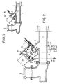
- Figure 1 is a schematic sectional view showing a known arrangement of a plasma torch on a cuff secured to a nozzle for injecting hot wind into a blast furnace.
- Figure 2 is a view similar to that of Figure 1, showing the device according to the invention.
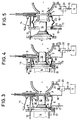
- Figures 3 and 4 are schematic sectional views showing the operation of the device of Figure 1.
- Figure 5 is a view of a variant.
- Figure 6 is a view of another variant.
- Figure 1 a diagram of a known arrangement in which the reference 1 designates a hot wind injection nozzle in a blast furnace, comprising a wind inlet 2 and an inclined sleeve 3 for the connection of a plasma torch 4, of the non-transferred arc type, this sleeve being provided with a shut-off valve 5 situated approximately in the middle of its length.
- valve operates in poor ⁇ P conditions, which have caused deformations of the valve shutter, resulting in difficulties in operating the valve, leaks and leaks.
- FIG. 2 shows the device according to the invention for implementing the method defined above.
- This device can be adapted to the arrangement of FIG. 1, practically without modification.
- This tubular member 6 may consist for example of metallic annular elements mounted to slide one inside the other in a telescopic and sealed manner, as known per se.
- the tubular member 6 is provided with a sealing collar 8 having in section a suitable shape for fitting tightly around a complementary sealing part 9 of the end of the torch 4 .
- At least one guide rod 10 is provided fixed parallel to the axis of the cuff 3 and on which the flange 8 of the tubular member 6 can slide, as well as a flange 11 of the torch, set back from his nose 12.
- the device also comprises at least one locking member 13 articulated on the edge of the flange 8 so as to be able to come into engagement with the flange 11 of the torch in order to maintain the latter in sealed contact with the flange; at least one other similar locking member 14 is articulated on the cuff 3 and adapted to cooperate outside the tubular member with the flange 11 of the torch, in order to retain the latter in the operating position, as is will describe below.
- conduit 15 connecting the interior of the tubular member 6 to the atmosphere via a tap 17, and another conduit 18 connecting the interior of the member 6 to a source of compressed air S by means of a tap 19 and of a pilot regulator 20 which is itself connected to the interior of the nozzle 1 by a duct 21 and a tap 22.
- FIG. 2 shows the torch 4 in the non-use position, in which the valve 5 is closed and the torch remote from the flange 8.
- valves 17, 19 and 22 are closed and the torch is made to slide on the guide 10 to bring the part 9 in tight contact with the flange 8 of the tubular member 6 and locks them together by means of the locking member 13, as shown in FIG. 3.
- the tubular member 6 delimits between the nose of the torch and the cuff 3 a sealed enclosure or airlock 16 of variable volume, closed at one of its ends by the nose of the torch 4 and at its opposite end by valve 5, closed.
- valves 19 and 22 are then opened in order to bring the airlock 16 to a pressure equal to that of the nozzle, or of the cuff downstream of the valve 5, by means of the pilot holder 20.
- the valve When the pressures are equalized, the valve is opened and the torch is advanced, thereby reducing at the same time the volume of the airlock 16, which is retracted, by simultaneously using the plasma gas from torch 4, without striking the arc electric and thus brings its nose to a station in contact with the periphery of the opening of the cuff 3.
- the torch is then locked in position by means of the locking member 14 on the flange 11, and the valve 17 is opened on the atmosphere so as to cool the interior of the airlock with air from the source S under a pressure controlled by the regulator-pilot 20 and approximately equal to that prevailing downstream of the valve 5.
- tubular member 6 is made of metal, for example stainless steel, in several elements sliding one inside the other as known per se.
- the annular member 23 is made of rubber, or other reinforced elastomer, for example a bellows brand "VIBROFIX” marketed by the company SNRI, all the other elements are similar to those of the first mode of achievement.
- the annular member 24 is mounted on a cuff 25 located behind the inlet 26 of hot wind and in the axis of the nozzle 27.
- the entire device is also identical in all respects to the previous example, either with a telescopic metal airlock or with an elastomer bellows.
- conduit 28 connecting the regulator 20 to the nozzle opens into the latter further downstream of the inlet 26 of hot wind ( Figure 6).
Landscapes
- Engineering & Computer Science (AREA)
- Chemical & Material Sciences (AREA)
- Manufacturing & Machinery (AREA)
- Materials Engineering (AREA)
- Metallurgy (AREA)
- Organic Chemistry (AREA)
- Plasma Technology (AREA)
- Manufacture Of Iron (AREA)
- Arc Welding In General (AREA)
- Feeding And Controlling Fuel (AREA)
- Gas Burners (AREA)
Claims (8)
- Verfahren zum Anbringen und Entfernen eines Plasmabrenners mit nicht übertragenem Lichtbogen an einem Ende eines mit einem Schieber versehenen Stutzens, wobei der Plasmabrenner mit einer Düse eines unter erhöhten Temperaturen und erhöhten Drücken arbeitetenden Gerätes kommuniziert, dadurch gekennzeichnet, daß zur Einnahme der Betriebsstellunga) ein geschlossener veränderlicher Hohlraum vor dem Schieber zwischen diesem und dem Ende des Brenners hergestellt wird,b) der Druck in diesem Hohlraum mit dem vor dem Schieber herrschenden Druck ausgeglichen wird,c) der Schieber geöffnet wird,d) dieser Hohlraum mit Hilfe des Schiebers durch Vorschieben des Brennermundstücks in die Betriebsstellung verkleinert wird, und daß zum Entfernen des Brennerse) der Hohlraum durch Rückziehen des Brennermundstücks vergrößert wird,f) der Schieber geschlossen wird,g) der Hohlraum auf atmosphärischen Druck, der niedriger als der hinter dem Schieber bestehene Druck ist, reduziert wird,h) der Hohlraum geöffnet wird.
- Vorrichtung zur Durchführung des Verfahrens nach Anspruch 1, dadurch gekennzeichnet, daß sie vor dem Schieber (5) mit einem ausziehbaren und wieder zusammenschiebbaren rohrförmigen Organ (6) versehen ist, das am einen Ende um das Ende (7) des Stutzens (3) dicht befestigt ist, indem dieses Ende (7) zur Aufnahme des Mundstücks (12) des Brenners (4) angepaßt ist, und am anderen Ende um das Mundstück herum Mittel (19, 20, 22, S) vorgesehen sind zur Herstellung des Ausgleichs des in diesem Organ (6) herrschenden Druckes mit dem hinter dem Schieber (5) vorhandenen Druck, sowie Mittel (17, 19, 20, 22, S) zur Kühlung des rohrförmigen Organs (6).
- Vorrichtung nach Anspruch 2, dadurch gekennzeichnet, daß das rohrförmige Organ (6) beweglich um das Mundstück des Brenners (4) herum angeordnet ist und hierzu sich ergänzende Abdichtmittel (8, 11) am Organ (6) und am Brenner (4), sowie Mittel (13) zur gegenseitigen Verriegelung/Absperrung dieses Elementes am Brenner aufweist.
- Vorrichtung nach Anspruch 2, dadurch gekennzeichnet, daß die genannten Mittel zum Ausgleich des Druckes im Organ (6) mit dem Druck hinter dem Schieber (5) eine Leitung (18) aufweisen, die das Innere des Organs (6) über einen Vorsteuerdruckminderer (20), der hinter dem Schieber (5) über einen Hahn (22) angeschlossen ist, mit einer Druckluftquelle (S) verbindet.
- Vorrichtung nach Anspruch 3, dadurch gekennzeichnet, daß das Abdichtelement (7) am Ende des Stutzens (3) als Vorsprung in das Innere des rohrförmigen Organs (6) hinein ragt.
- Vorrichtung nach einem der Ansprüche 2 bis 5, dadurch gekennzeichnet, daß das rohrförmige Organ (6, 24) aus Metallelementen besteht, die teleskopartig ineinander verschiebbar sind.
- Vorrichtung nach einem der Ansprüche 2 bis 5, dadurch gekennzeichnet, daß das ringförmige Organ (23) eine Manschette aus verstärktem Elastomer ist.
- Vorrichtung nach einem der vorangehenden Ansprüche, dadurch gekennzeichnet, daß sie an einem mit der Achse der Düse (27) fluchtenden Stutzen (25) angebracht ist.
Applications Claiming Priority (2)
| Application Number | Priority Date | Filing Date | Title |
|---|---|---|---|
| FR8812899A FR2637443B1 (fr) | 1988-10-03 | 1988-10-03 | Procede et dispositif pour la mise a poste et le retrait d'une torche a plasma sur un appareil fonctionnant dans des conditions de pression et de temperature interdisant une intervention directe |
| FR8812899 | 1988-10-03 |
Publications (2)
| Publication Number | Publication Date |
|---|---|
| EP0363246A1 EP0363246A1 (de) | 1990-04-11 |
| EP0363246B1 true EP0363246B1 (de) | 1993-05-05 |
Family
ID=9370622
Family Applications (1)
| Application Number | Title | Priority Date | Filing Date |
|---|---|---|---|
| EP89402600A Expired - Lifetime EP0363246B1 (de) | 1988-10-03 | 1989-09-22 | Vorrichtung zum Anbringen und Entfernen eines Plasmabrenners in einen Apparat, der unter einem solchen Druck und einer solchen Temperatur arbeitet, dass direktes Arbeiten unmöglich ist |
Country Status (7)
| Country | Link |
|---|---|
| US (1) | US4997475A (de) |
| EP (1) | EP0363246B1 (de) |
| JP (1) | JPH0665195B2 (de) |
| CA (1) | CA1310075C (de) |
| DE (1) | DE68906347T2 (de) |
| ES (1) | ES2039902T3 (de) |
| FR (1) | FR2637443B1 (de) |
Families Citing this family (2)
| Publication number | Priority date | Publication date | Assignee | Title |
|---|---|---|---|---|
| LU88280A1 (fr) * | 1993-05-27 | 1994-12-01 | Wurth Paul Sa | Dispositif pour introduire une lance dans un réservoir sous pression, notamment un haut fourneau |
| US9599333B2 (en) | 2013-11-08 | 2017-03-21 | Air Products And Chemicals, Inc. | Burner retraction system |
Family Cites Families (7)
| Publication number | Priority date | Publication date | Assignee | Title |
|---|---|---|---|---|
| GB303510A (en) * | 1928-01-06 | 1929-12-05 | Thery Rene | Improvements in or relating to furnaces heated by oil burners |
| US2924269A (en) * | 1956-10-01 | 1960-02-09 | United States Steel Corp | Blast furnace stove gas-port and burner nozzle connection |
| GB1231684A (de) * | 1968-04-30 | 1971-05-12 | ||
| US4477248A (en) * | 1983-08-04 | 1984-10-16 | Dulac Robert R | Oil burner shutter |
| FR2566802B1 (fr) * | 1984-07-02 | 1986-12-05 | Aerospatiale | Procede pour le rechauffage du gaz de soufflage d'un haut fourneau par un generateur de plasma |
| SE451756B (sv) * | 1984-10-19 | 1987-10-26 | Skf Steel Eng Ab | Plasmageneratorinstallation i schaktugn |
| US4769065A (en) * | 1987-05-08 | 1988-09-06 | Electric Power Research Institute | Control of a plasma fired cupola |
-
1988
- 1988-10-03 FR FR8812899A patent/FR2637443B1/fr not_active Expired - Fee Related
-
1989
- 1989-09-18 CA CA000611691A patent/CA1310075C/fr not_active Expired - Fee Related
- 1989-09-22 EP EP89402600A patent/EP0363246B1/de not_active Expired - Lifetime
- 1989-09-22 ES ES198989402600T patent/ES2039902T3/es not_active Expired - Lifetime
- 1989-09-22 DE DE8989402600T patent/DE68906347T2/de not_active Expired - Fee Related
- 1989-09-26 US US07/412,860 patent/US4997475A/en not_active Expired - Fee Related
- 1989-10-02 JP JP1255353A patent/JPH0665195B2/ja not_active Expired - Lifetime
Also Published As
| Publication number | Publication date |
|---|---|
| CA1310075C (fr) | 1992-11-10 |
| DE68906347D1 (de) | 1993-06-09 |
| US4997475A (en) | 1991-03-05 |
| JPH02168596A (ja) | 1990-06-28 |
| DE68906347T2 (de) | 1993-08-12 |
| ES2039902T3 (es) | 1993-10-01 |
| EP0363246A1 (de) | 1990-04-11 |
| FR2637443A1 (fr) | 1990-04-06 |
| JPH0665195B2 (ja) | 1994-08-22 |
| FR2637443B1 (fr) | 1990-11-02 |
Similar Documents
| Publication | Publication Date | Title |
|---|---|---|
| CH690506A5 (fr) | Soupage d'échappement sous vide. | |
| FR2670177A1 (fr) | Joint d'etancheite entre l'arriere du fuselage d'un avion et les volets exterieurs de son turboreacteur. | |
| EP0296032A1 (de) | Verbrennungssystem mit hoher Abgasaustrittsgeschwindigkeit | |
| EP0363246B1 (de) | Vorrichtung zum Anbringen und Entfernen eines Plasmabrenners in einen Apparat, der unter einem solchen Druck und einer solchen Temperatur arbeitet, dass direktes Arbeiten unmöglich ist | |
| EP0969239A1 (de) | Abschaltgerät für unter Druck stehende Flüssigkeitshandhabungs-Anlage | |
| FR2995361A1 (fr) | Dispositif de bouchage d'une ouverture d'une paroi d'enceinte pour l'acces a un arbre rotatif. | |
| FR2672882A1 (fr) | Systeme de remplissage de reservoir pour un vehicule a moteur fonctionnant a l'hydrogene cryogenique. | |
| CA1200689A (fr) | Embout de lance de gunitage a chaud | |
| EP0065922B1 (de) | Primärpumpe für einen Druckwasserreaktor, mit einem Dichtungssystem für ihre Antriebswelle | |
| FR3036442A1 (fr) | Turbomachine comportant un systeme de ventilation | |
| EP0170566A1 (de) | Verfahren zur Heizung des Heisswindes eines Hochofens mit Hilfe eines Plasmabrenners | |
| EP1034310A1 (de) | Verfahren zur kühlung einer beschickungsanlage eines schachtofens | |
| EP0052567B1 (de) | Verfahren und Vorrichtung zum Entfernen des Dichtungsmaterials einer Dichtungsbüchse | |
| EP0018882A1 (de) | Verfahren zur Verringerung der Entzündungs- und Explosionsgefahr infolge des Zerfalls von Hochdruckäthylen und Vorrichtung zur Durchführung des Verfahrens | |
| EP3841022B1 (de) | Vorrichtung und verfahren zur handhabung einer flugzeugantriebsanordnung | |
| FR2672117A1 (fr) | Dispositif de fusion a induction sous vide, comportant des branchements de refroidissement et d'alimentation de puissance manóoeuvrables simultanement. | |
| EP0363247B1 (de) | Vorrichtung zum Anbringen und Entfernen eines Plasmabrenners in einen Apparat, der unter einem solchen Druck und einer solchen Temperatur arbeitet, dass direktes Arbeiten unmöglich ist | |
| EP0073168A2 (de) | Brenner zum Schneiden, Schweissen oder Erwärmen | |
| FR2645062A1 (fr) | Pistolet pneumatique de sablage pour le decapage local de surfaces a metalliser | |
| EP0536016A1 (de) | Kühleinrichtung für Telemanipulator und seine Anwendung für eine Intervention in feindlichem Bereich unter hoher Temperatur | |
| EP0254659A1 (de) | Verschlusskappe für Sonde, Verfahren und Vorrichtung zur Probenentnahme bei Schmelzöfen mit einer solchen Sonde | |
| EP0084785B1 (de) | Schnelles Abschrecken eines Metalles oder einer Metallegierung auf einem Band | |
| EP2178761A1 (de) | Sperrvorrichtung | |
| FR2685008A1 (fr) | Dispositif d'enlevement de residus solides formes dans une enceinte soumise a haute temperature. | |
| EP0238412B1 (de) | Verfahren und Vorrichtung zum Ausführen von Arbeiten an einem im Betrieb befindlichen Gasrohr |
Legal Events
| Date | Code | Title | Description |
|---|---|---|---|
| PUAI | Public reference made under article 153(3) epc to a published international application that has entered the european phase |
Free format text: ORIGINAL CODE: 0009012 |
|
| 17P | Request for examination filed |
Effective date: 19891003 |
|
| AK | Designated contracting states |
Kind code of ref document: A1 Designated state(s): BE DE ES GB IT SE |
|
| RAP1 | Party data changed (applicant data changed or rights of an application transferred) |
Owner name: AEROSPATIALE SOCIETE NATIONALE INDUSTRIELLE |
|
| 17Q | First examination report despatched |
Effective date: 19920918 |
|
| GRAA | (expected) grant |
Free format text: ORIGINAL CODE: 0009210 |
|
| ITF | It: translation for a ep patent filed | ||
| AK | Designated contracting states |
Kind code of ref document: B1 Designated state(s): BE DE ES GB IT SE |
|
| GBT | Gb: translation of ep patent filed (gb section 77(6)(a)/1977) |
Effective date: 19930505 |
|
| REF | Corresponds to: |
Ref document number: 68906347 Country of ref document: DE Date of ref document: 19930609 |
|
| REG | Reference to a national code |
Ref country code: ES Ref legal event code: FG2A Ref document number: 2039902 Country of ref document: ES Kind code of ref document: T3 |
|
| PLBE | No opposition filed within time limit |
Free format text: ORIGINAL CODE: 0009261 |
|
| STAA | Information on the status of an ep patent application or granted ep patent |
Free format text: STATUS: NO OPPOSITION FILED WITHIN TIME LIMIT |
|
| 26N | No opposition filed | ||
| EAL | Se: european patent in force in sweden |
Ref document number: 89402600.4 |
|
| PGFP | Annual fee paid to national office [announced via postgrant information from national office to epo] |
Ref country code: ES Payment date: 19970901 Year of fee payment: 9 |
|
| PGFP | Annual fee paid to national office [announced via postgrant information from national office to epo] |
Ref country code: GB Payment date: 19970909 Year of fee payment: 9 |
|
| PGFP | Annual fee paid to national office [announced via postgrant information from national office to epo] |
Ref country code: DE Payment date: 19970913 Year of fee payment: 9 |
|
| PGFP | Annual fee paid to national office [announced via postgrant information from national office to epo] |
Ref country code: SE Payment date: 19970925 Year of fee payment: 9 |
|
| PGFP | Annual fee paid to national office [announced via postgrant information from national office to epo] |
Ref country code: BE Payment date: 19970929 Year of fee payment: 9 |
|
| PG25 | Lapsed in a contracting state [announced via postgrant information from national office to epo] |
Ref country code: GB Free format text: LAPSE BECAUSE OF NON-PAYMENT OF DUE FEES Effective date: 19980922 |
|
| PG25 | Lapsed in a contracting state [announced via postgrant information from national office to epo] |
Ref country code: SE Free format text: LAPSE BECAUSE OF NON-PAYMENT OF DUE FEES Effective date: 19980923 Ref country code: ES Free format text: LAPSE BECAUSE OF THE APPLICANT RENOUNCES Effective date: 19980923 |
|
| PG25 | Lapsed in a contracting state [announced via postgrant information from national office to epo] |
Ref country code: BE Free format text: LAPSE BECAUSE OF NON-PAYMENT OF DUE FEES Effective date: 19980930 |
|
| BERE | Be: lapsed |
Owner name: AEROSPATIALE SOC. NATIONALE INDUSTRIELLE Effective date: 19980930 |
|
| GBPC | Gb: european patent ceased through non-payment of renewal fee |
Effective date: 19980922 |
|
| EUG | Se: european patent has lapsed |
Ref document number: 89402600.4 |
|
| PG25 | Lapsed in a contracting state [announced via postgrant information from national office to epo] |
Ref country code: DE Free format text: LAPSE BECAUSE OF NON-PAYMENT OF DUE FEES Effective date: 19990701 |
|
| REG | Reference to a national code |
Ref country code: ES Ref legal event code: FD2A Effective date: 20001009 |
|
| PG25 | Lapsed in a contracting state [announced via postgrant information from national office to epo] |
Ref country code: IT Free format text: LAPSE BECAUSE OF NON-PAYMENT OF DUE FEES;WARNING: LAPSES OF ITALIAN PATENTS WITH EFFECTIVE DATE BEFORE 2007 MAY HAVE OCCURRED AT ANY TIME BEFORE 2007. THE CORRECT EFFECTIVE DATE MAY BE DIFFERENT FROM THE ONE RECORDED. Effective date: 20050922 |