EP0363406B1 - Ecoutille de protection pour sortir verticalement d'un abri - Google Patents
Ecoutille de protection pour sortir verticalement d'un abri Download PDFInfo
- Publication number
- EP0363406B1 EP0363406B1 EP88904916A EP88904916A EP0363406B1 EP 0363406 B1 EP0363406 B1 EP 0363406B1 EP 88904916 A EP88904916 A EP 88904916A EP 88904916 A EP88904916 A EP 88904916A EP 0363406 B1 EP0363406 B1 EP 0363406B1
- Authority
- EP
- European Patent Office
- Prior art keywords
- connecting sleeve
- cover
- protective hatch
- dome
- air
- Prior art date
- Legal status (The legal status is an assumption and is not a legal conclusion. Google has not performed a legal analysis and makes no representation as to the accuracy of the status listed.)
- Expired - Lifetime
Links
Images

Classifications
-
- E—FIXED CONSTRUCTIONS
- E06—DOORS, WINDOWS, SHUTTERS, OR ROLLER BLINDS IN GENERAL; LADDERS
- E06B—FIXED OR MOVABLE CLOSURES FOR OPENINGS IN BUILDINGS, VEHICLES, FENCES OR LIKE ENCLOSURES IN GENERAL, e.g. DOORS, WINDOWS, BLINDS, GATES
- E06B5/00—Doors, windows, or like closures for special purposes; Border constructions therefor
- E06B5/10—Doors, windows, or like closures for special purposes; Border constructions therefor for protection against air-raid or other war-like action; for other protective purposes
- E06B5/12—Doors, windows, or like closures for special purposes; Border constructions therefor for protection against air-raid or other war-like action; for other protective purposes against air pressure, explosion, or gas
Definitions
- the invention relates to a protective hatch according to the preamble of patent claim 1.
- EP-A-104 519 describes a protective hatch of the type mentioned at the outset, in which a protective collar is arranged below the cover as a pipe socket and is formed from a circular hollow profile with a rectangular cross section. Its axial length corresponds to approximately 6% of the diameter of the cover. To watch the cover, together with its pipe socket, is only lifted by the lifting device to such an extent that a slot created between the pipe socket and the upper end wall 16 is sufficient for viewing. A gas-tight seal between the interior of the shelter system and the outside world is no longer guaranteed under these circumstances. There is no protection against the pressure and suction waves after atomic detonation.
- the lids that open upwards cannot be pushed up in any case if debris or other heavy materials have accumulated above them.
- the entire, dome-shaped roof is raised by means of a hydraulic device in order to provide access to the outside world. Loads on such a roof can be pushed up by means of the hydraulic lifting device, but the known arrangement does not allow an observation position, the interior of the known shelter system is in direct contact with the outside world as soon as the roof is raised even slightly.
- the invention is based on the object of developing the protective hatch of the type mentioned at the outset from EP-A 104 519 in such a way that it is tight against pressure and suction waves and enables observation even when the seal is maintained.
- a protective hatch in which the cover and pipe socket are integrally connected to one another and the length of the pipe socket is approximately half the outer diameter of the cover, in which observation windows are used in a gastight manner in the pipe socket and preferably in the vicinity of the cover and at a second seal is arranged on the outer wall of the pipe socket as close as possible to a lower edge of the pipe socket, which lies against the inner wall of the recess.
- the metallic hood Due to the relatively long pipe socket, there is a large overlap between the recess and the hood, which reduces the risk of leaks. Due to the relatively long pipe socket, the metallic hood is stiffened in such a way that it can also withstand the pressure and suction waves that occur with atomic detonations. It is supported against the pressure wave by means of its edge area on the upper end wall, as a result of which a secure seal and high mechanical strength are achieved. When a suction wave acts on it, the edge region can lift off from the upper end wall without the seal being lost as a result. A full leak is only achieved when the hood is pulled out of the recess so far that your pipe socket is released. Sufficient mechanical precautions can be taken against this. The only important thing is that the hood can be raised by a certain amount, so no rigid attachment is necessary, but the seal is not lost.
- the observation windows in the pipe socket and preferably in the vicinity of the cover are used in a gas-tight manner, an intermediate position of the hood between the erroneous closed position and its open position can be used for observing the surroundings, without the sealing hatch being lost to the outside world.
- the invention suggests a closure that is more like a cork in a bottle neck and seals as long as it is inside the bottle neck.
- the lifting device can preferably be blocked or switched so that it exerts a permanent pull on the hood. As a result, the hood is pressed into the sealing position. A violent opening from the outside, whether by the suction wave or by other causes, is made more difficult. It has also proven to be advantageous here to let the cover into the upper end wall to such an extent that it does not protrude from it. It is practically impossible to pry the hood open from the outside.
- the protective hatch for vertical exit from a preferably underground shelter system, to which reference number 10 is pointed out, has a metallic hood 12 which is inserted into a recess 14 of an upper end wall 16 made of concrete.
- This end wall is preferably a cylindrical cover plate of an outlet pipe of an underground protective bunker system, as is known from German Patent 31 44 141.
- the recess 14 is limited in the exemplary embodiment shown by concrete, it is by careful formwork, z. B. steel formwork, made when casting the end wall 16. However, in another embodiment, it can also be limited by a metal socket which is connected to the end wall 16.
- the recess 14 is essentially cylindrical, it has a gradation 18 in the uppermost region.
- the gradation 18 is practically completely filled by the hood 12, provided that it is in the closed position shown in FIG. 1.
- the hood 12 consists essentially of a dome-shaped cover 22 which is convex towards the outer region 20 and a pipe socket 24 which is integrally connected to the latter.
- the latter has an outer diameter which is only insignificantly smaller than the clear inner diameter of the recess 14 and thus also the hood 12 is round in cross section, this is a preferred embodiment. Basically, it can also be angular, z. B. produce polygonal designs.
- the outer diameter of the cover 22 is approximately 90 cm.
- the length of the pipe socket is about half the outer diameter of the cover.
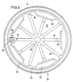
- the cover is stiffened by a total of ten ribs running in a star shape, it is smooth on the outside and forms a spherical cap.
- the wall thickness of the cover 22 is approximately 25 to 50 mm, the ribs 26 project approximately 12 cm inwards. They leave a central area 28 of about 6 cm inside diameter free in that there is an internal thread into which a closure body 29 in the form of a grub screw is tightly screwed. It can be removed, in its place there is an additional safety valve to be built in.
- the hood 12 is made of cast aluminum, for example GAlSi 12, or a cast steel.
- the wall thickness of the pipe socket 24 is comparable to the wall thickness of the cover 22, and the pipe socket 24 is stiffened by inner ribs 30, which can be seen in FIGS. 1 and 4, and towards the lower, free edge 32 of the hood 12 to a small height of leak a few millimeters.
- the cover 22 has an edge region 34 which projects over the pipe socket 24 and which is shaped in accordance with the gradation 18.
- a first seal is provided on the inner groove of the edge area, which is made as a circular ring made of elastic material.
- Fig. 2 the relaxed state of this seal 36 is shown, from this figure it can be seen that the outer, lower edge of the seal 36 comes to rest when closing the hood 12 on a plateau of the gradation 18 before the actual closing process is completed . In this area, the seal 36 is also compressed the most. Dimensional tolerances are compensated for by the construction described.
- the height of the gradation 18 corresponds to the height of the edge region 34, as a result of which the top of the cover 22 merges smoothly into the curved top of the cover 22.
- the gap between cover 22 and step 18 is chosen to be as small as possible, and it is also conical. These measures make it difficult to attach a tool for prying open the hood 12 from the outer region 20.
- a pipe 38 is provided on the pipe socket 24, which is connected to it in one piece and extends over its entire length, for receiving an actuating rod 40; the details can be seen from FIGS. 1 and 4.
- the actuating rod 40 is connected to the cover 22 of the hood 12 by suitable measures, in the exemplary embodiment shown this is done by a screw 42 which is accessible from the outer area 20.
- the actuating rod 40 can also be secured by a pin within its channel 38, into which it fits without play.
- the actuating rod is guided through at least one clamp 44 and held, this is, as Fig. 1 shows, attached to the concrete body of the shelter system 10.
- the lower free edge 32 of the hood 12 is at the same height as the lower edge of the end wall 16 (in the closed position according to FIG. 1).
- 46 denotes a section of the cylinder of the outlet pipe. A seal, which can be seen in FIG. 1, is interposed between the two.
- the clamp 44 is directly attached to a central tensioning tube which runs in the outlet tube 46.
- a hydraulic lifting device of a known type, not shown in the figures.
- a spindle drive or another drive device that enables vertical movement of the actuating rod 40 can also be provided.
- the drive device is designed so that the load located on the top of the cover 22 can be raised, for example due to debris.
- the actuating rod can be pivoted relative to the lifting device, as will be described later.
- a second seal 48 projects outwards on the outer jacket of the pipe socket 24, which is also designed as a flat cylinder ring. With its free, outer end region, it grinds against the cylindrical inner wall of the recess 14.
- a total of five observation windows 50 are provided.
- slots are formed in the pipe socket 24, behind which webs 52 formed during casting are located, between which two prisms 54, 56 are arranged. They are pressed against the webs 54 by means of a plate 58 (see FIG. 3).
- the observation window 50 can be arranged relatively close to the edge region 34, because the offset of the light path gives enough space for an observation below the cover 22.
- the hood 12 is raised above the actuating rod 40 to such an extent that the slots in the observation window 50 lie above the surface of the end wall 16, the surroundings can be observed through the five observation windows, the seal against the outside world being maintained via the second seal 48 .
- This seal is additionally supported by the fact that an overpressure is maintained in the inner region with respect to the outer region 20, so that in the event of a leak in the region of the second seal air flows outwards at this leak point, in any event no air can enter below the hood 12.
- the actuating rod 40 and thus the hood 12 can be pivoted, preferably it is pivoted through 180 degrees, as a result of which practically the whole is clear space of the recess 14 free for the exit upwards.
- the lifting device is preferably designed such that the actuating rod 40 can also be pulled down, as a result of which the seal 36 is pressed against the step 18.
- This coating 60 is material such as is also used for missiles which are intended to be immersed in the earth's atmosphere again after a flight.
Landscapes
- Engineering & Computer Science (AREA)
- Civil Engineering (AREA)
- Structural Engineering (AREA)
- Tents Or Canopies (AREA)
- Buildings Adapted To Withstand Abnormal External Influences (AREA)
- Pressure Vessels And Lids Thereof (AREA)
Claims (8)
Priority Applications (1)
| Application Number | Priority Date | Filing Date | Title |
|---|---|---|---|
| AT88904916T ATE73889T1 (de) | 1987-06-16 | 1988-06-09 | Schutzluke fuer den vertikalen ausstieg aus einer schutzraumanlage. |
Applications Claiming Priority (2)
| Application Number | Priority Date | Filing Date | Title |
|---|---|---|---|
| DE8708487U | 1987-06-16 | ||
| DE8708487U DE8708487U1 (de) | 1987-06-16 | 1987-06-16 | Schutzluke für den vertikalen Ausstieg aus einer Schutzraumanlage |
Publications (2)
| Publication Number | Publication Date |
|---|---|
| EP0363406A1 EP0363406A1 (fr) | 1990-04-18 |
| EP0363406B1 true EP0363406B1 (fr) | 1992-03-18 |
Family
ID=6809202
Family Applications (1)
| Application Number | Title | Priority Date | Filing Date |
|---|---|---|---|
| EP88904916A Expired - Lifetime EP0363406B1 (fr) | 1987-06-16 | 1988-06-09 | Ecoutille de protection pour sortir verticalement d'un abri |
Country Status (4)
| Country | Link |
|---|---|
| EP (1) | EP0363406B1 (fr) |
| AT (1) | ATE73889T1 (fr) |
| DE (2) | DE8708487U1 (fr) |
| WO (1) | WO1988010353A1 (fr) |
Family Cites Families (6)
| Publication number | Priority date | Publication date | Assignee | Title |
|---|---|---|---|---|
| FR857211A (fr) * | 1939-07-03 | 1940-08-31 | Acieries De Sambre Et Meuse | Guérite-abri |
| GB577933A (en) * | 1940-07-12 | 1946-06-06 | Francis Norman Pickett | An improved means for the protection of aerodromes, aircraft landing fields and other situations |
| US2395310A (en) * | 1942-09-10 | 1946-02-19 | Wilson John Hart | Armament structure |
| US2792794A (en) * | 1955-05-26 | 1957-05-21 | William H Miller | Bomb shelter |
| ATE23924T1 (de) * | 1982-09-27 | 1986-12-15 | Heierli Werner | Schutzvorrichtung zum beobachten und verteidigen, insbesondere fuer die infanterie und fuer bewachungsaufgaben. |
| DE3604466A1 (de) * | 1986-02-13 | 1987-08-20 | Hoesch Ag | Transportable zivilschutzvorrichtung |
-
1987
- 1987-06-16 DE DE8708487U patent/DE8708487U1/de not_active Expired
-
1988
- 1988-06-09 EP EP88904916A patent/EP0363406B1/fr not_active Expired - Lifetime
- 1988-06-09 DE DE8888904916T patent/DE3869413D1/de not_active Expired - Lifetime
- 1988-06-09 AT AT88904916T patent/ATE73889T1/de active
- 1988-06-09 WO PCT/DE1988/000345 patent/WO1988010353A1/fr not_active Ceased
Also Published As
| Publication number | Publication date |
|---|---|
| EP0363406A1 (fr) | 1990-04-18 |
| DE3869413D1 (de) | 1992-04-23 |
| WO1988010353A1 (fr) | 1988-12-29 |
| ATE73889T1 (de) | 1992-04-15 |
| DE8708487U1 (de) | 1987-08-27 |
Similar Documents
| Publication | Publication Date | Title |
|---|---|---|
| DE2551086A1 (de) | Einrichtung zur zeitweisen abdichtung des innenraumes von gepanzerten fahrzeugen, insbesondere von kampfpanzern, gegen das eindringen von fluessigen oder gasfoermigen stoffen | |
| DE2824305C2 (de) | Vorrichtung zum Absperren von Gasleitungen großen Querschnitts | |
| EP0110037B1 (fr) | Véhicule de combat, notamment char de combat blindé | |
| DE3305882C2 (fr) | ||
| EP0033139B1 (fr) | Vanne d'arrêt de pression et bouteille de gaz pourvue de cette vanne | |
| EP3582231B1 (fr) | Récipient destiné à la réception des déchets radioactif et récipient agrégat | |
| EP1484574A1 (fr) | Conteneur de sécurité pour une bombe explosive | |
| DE4225997A1 (de) | Schnellöffnungsventil | |
| EP0368870B1 (fr) | Porte de protection pour installations anti-aeriennes et centrales nucleaires | |
| DE102016200206A1 (de) | Entnahmearmatur für flüssigkeitsbehälter | |
| EP0363406B1 (fr) | Ecoutille de protection pour sortir verticalement d'un abri | |
| EP0428953A1 (fr) | Véhicule blindé de combat, en particulier char | |
| CH678092A5 (fr) | ||
| DE2806011A1 (de) | Personen-kontrollzelle | |
| DE3304626C2 (de) | Tuer mit einem riegelwerk | |
| DE102016008035A1 (de) | Tankventil | |
| DE3142674A1 (de) | "tankcontainer" | |
| DE1240196B (de) | Transfervorrichtung fuer radioaktive Gegenstaende | |
| DE3348343C2 (de) | Tür mit einem Riegelwerk | |
| DE1509762C3 (de) | Deckelverschluß | |
| DE202005019900U1 (de) | Gesicherte Schachtabdeckung | |
| DE1428587A1 (de) | Druck- und gasdichte Schleuse | |
| EP0564968A2 (fr) | Récipient pulvérisateur rempli d'un gaz propulseur | |
| DE9200144U1 (de) | Klappenventil | |
| DE3407082A1 (de) | Vorrichtung zur erstellung eines schutzraumes |
Legal Events
| Date | Code | Title | Description |
|---|---|---|---|
| PUAI | Public reference made under article 153(3) epc to a published international application that has entered the european phase |
Free format text: ORIGINAL CODE: 0009012 |
|
| 17P | Request for examination filed |
Effective date: 19891108 |
|
| AK | Designated contracting states |
Kind code of ref document: A1 Designated state(s): AT CH DE FR GB LI |
|
| 17Q | First examination report despatched |
Effective date: 19901025 |
|
| GRAA | (expected) grant |
Free format text: ORIGINAL CODE: 0009210 |
|
| AK | Designated contracting states |
Kind code of ref document: B1 Designated state(s): AT CH DE FR GB LI |
|
| PG25 | Lapsed in a contracting state [announced via postgrant information from national office to epo] |
Ref country code: GB Effective date: 19920318 Ref country code: FR Effective date: 19920318 |
|
| REF | Corresponds to: |
Ref document number: 73889 Country of ref document: AT Date of ref document: 19920415 Kind code of ref document: T |
|
| REF | Corresponds to: |
Ref document number: 3869413 Country of ref document: DE Date of ref document: 19920423 |
|
| PG25 | Lapsed in a contracting state [announced via postgrant information from national office to epo] |
Ref country code: AT Effective date: 19920609 |
|
| PG25 | Lapsed in a contracting state [announced via postgrant information from national office to epo] |
Ref country code: LI Effective date: 19920630 Ref country code: CH Effective date: 19920630 |
|
| EN | Fr: translation not filed | ||
| GBV | Gb: ep patent (uk) treated as always having been void in accordance with gb section 77(7)/1977 [no translation filed] | ||
| PLBE | No opposition filed within time limit |
Free format text: ORIGINAL CODE: 0009261 |
|
| STAA | Information on the status of an ep patent application or granted ep patent |
Free format text: STATUS: NO OPPOSITION FILED WITHIN TIME LIMIT |
|
| REG | Reference to a national code |
Ref country code: CH Ref legal event code: PL |
|
| PG25 | Lapsed in a contracting state [announced via postgrant information from national office to epo] |
Ref country code: DE Effective date: 19930302 |
|
| 26N | No opposition filed |