EP0363450B1 - Dispositif de pipettage - Google Patents
Dispositif de pipettage Download PDFInfo
- Publication number
- EP0363450B1 EP0363450B1 EP89902221A EP89902221A EP0363450B1 EP 0363450 B1 EP0363450 B1 EP 0363450B1 EP 89902221 A EP89902221 A EP 89902221A EP 89902221 A EP89902221 A EP 89902221A EP 0363450 B1 EP0363450 B1 EP 0363450B1
- Authority
- EP
- European Patent Office
- Prior art keywords
- pipettes
- plate
- valve plate
- carrier plate
- channels
- Prior art date
- Legal status (The legal status is an assumption and is not a legal conclusion. Google has not performed a legal analysis and makes no representation as to the accuracy of the status listed.)
- Expired - Lifetime
Links
- 239000007788 liquid Substances 0.000 claims abstract description 9
- 238000007789 sealing Methods 0.000 claims description 8
- 239000004033 plastic Substances 0.000 claims description 4
- 239000004809 Teflon Substances 0.000 claims description 2
- 229920006362 Teflon® Polymers 0.000 claims description 2
- 229920001971 elastomer Polymers 0.000 claims description 2
- 239000000806 elastomer Substances 0.000 claims description 2
- 238000003825 pressing Methods 0.000 claims description 2
- 238000005507 spraying Methods 0.000 claims description 2
- 239000007921 spray Substances 0.000 claims 1
- 238000002347 injection Methods 0.000 abstract 1
- 239000007924 injection Substances 0.000 abstract 1
- 238000000034 method Methods 0.000 description 2
- 238000003860 storage Methods 0.000 description 2
- 241001631457 Cannula Species 0.000 description 1
- 239000003153 chemical reaction reagent Substances 0.000 description 1
- 230000006835 compression Effects 0.000 description 1
- 238000007906 compression Methods 0.000 description 1
- 238000010276 construction Methods 0.000 description 1
- 238000010586 diagram Methods 0.000 description 1
- 238000006073 displacement reaction Methods 0.000 description 1
- 238000009826 distribution Methods 0.000 description 1
- 230000000694 effects Effects 0.000 description 1
- 238000004519 manufacturing process Methods 0.000 description 1
- 239000000463 material Substances 0.000 description 1
- 230000002572 peristaltic effect Effects 0.000 description 1
- 238000010079 rubber tapping Methods 0.000 description 1
- 238000005406 washing Methods 0.000 description 1
Images

Classifications
-
- G—PHYSICS
- G01—MEASURING; TESTING
- G01N—INVESTIGATING OR ANALYSING MATERIALS BY DETERMINING THEIR CHEMICAL OR PHYSICAL PROPERTIES
- G01N35/00—Automatic analysis not limited to methods or materials provided for in any single one of groups G01N1/00 - G01N33/00; Handling materials therefor
- G01N35/10—Devices for transferring samples or any liquids to, in, or from, the analysis apparatus, e.g. suction devices, injection devices
-
- G—PHYSICS
- G01—MEASURING; TESTING
- G01N—INVESTIGATING OR ANALYSING MATERIALS BY DETERMINING THEIR CHEMICAL OR PHYSICAL PROPERTIES
- G01N35/00—Automatic analysis not limited to methods or materials provided for in any single one of groups G01N1/00 - G01N33/00; Handling materials therefor
- G01N35/10—Devices for transferring samples or any liquids to, in, or from, the analysis apparatus, e.g. suction devices, injection devices
- G01N35/1004—Cleaning sample transfer devices
- G01N2035/1006—Rinsing only the inside of the tip
Definitions
- the invention is in the field of analytical laboratory equipment and relates to a metering device with a plurality of metering pumps which can be actuated simultaneously, preferably pipettes which are actuated with a piston.
- dosing pumps that are particularly suitable for automation, of which the piston dosing devices still occupy a central position.
- Peristaltic pumps are also used for dosing, as are movable dosing channels with which part of the liquid column can be separated. All of these metering pumps are also used in arrangements of several, in order, for example, to be able to receive and / or dispense a large number of identical volumes at the same time. Often the pump should be washed out and filled with another liquid in between. This necessitated valves with which these processes can only be controlled and thus automated.
- such a device is described in US Pat. No. 4106911. It includes a plurality of plunger syringes, the plungers of which are driven by a central drive to simultaneously fill and empty the syringes.
- Appropriately shaped storage or collecting vessels are placed in the area of the syringe outlets, from which liquid is sucked into the syringe or released into the liquid from the syringe. These vessels have to be replaced for each working step of the device. The change is carried out manually for the device described. Automation would involve moving relatively large weights over relatively large distances and would therefore determine the speed of the function of the entire device.
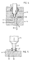
- Figures 1 to 3 show the same embodiment in three different working positions, namely: Figure 1 suction, mixing in a microtest plate (MTP); FIG. 2 sucking up from a storage container, dispensing, washing; Figure 3 Dispose of in a collection container.
- the various working positions are brought about by moving device parts. Shown is one of a multitude of similar valve functions on a pipette, all of which are operative at the same time. Another pipette is shown. In fact, in the embodiment under discussion there are 96 of them which are arranged in a mirror-image grid (array) corresponding to the cavities of a microtiter plate.
- the device discussed essentially consists of a first motor drive 1, which drives a plurality of syringe pistons 6 displaceable on a piston rod 7 via a spindle 1 ', preferably in the vertical direction z; from a second motor drive 2, which drives a carrier plate 3 via a spindle 2 ', preferably in the horizontal direction; a fixed one Valve plate 4 with a channel system 10 consisting of the channels 11, 12, 13 and a plurality of pipette cylinders 5, which are arranged in the carrier plate 3 in a manner to be shown later.
- the majority of the pipettes consist of 96 copies, each pipette here being assigned 3 channels of the channel system 10, that is to say that the valve plate 4 in its side facing the carrier plate 288 has inlet openings which can be connected to the pipettes by displacing the carrier plate can optionally be brought into an operative connection.
- the channel system 10 here consists of reagent supply channels 12 (for all 96 pipettes), disposal channels 11 (for all 96 pipettes) and channels 13 for operating the MTP cavities (for all 96 pipettes).
- the operating channels continue, for example.
- In the form of a hollow needle 13 ' which can be inserted into the cavity of the MTP.
- the device looks rather spiky, 96 needles protrude from the valve plate arranged in the MTP grid.
- the microtiter plates are brought up to these needles for processing.
- hollow needles for the continuation 13 'of the channels 13 commercially available disposable plastic tips, which can be replaced or replaced if necessary, can be used.
- the exchange of such plastic tips can also be carried out automatically by means of a perforated plate-like device with inserted new tips, which is inserted into the MTP feed device.
- the channel system 10 is through a network (preferably as in a chessboard at right angles to each other) from the valve plate 4 through holes in two levels (for filling and for disposal), into which holes the connections to the 96 inlet openings open and which two hole networks in a common Outlet. All other openings to the supply network due to the manufacture are closed. Several tapping points on the network outside this can also be brought together to form a common inlet / outlet.
- all duct parts are filled with liquid and free of air bubbles. It is advantageous to start with a filling stroke through the feed channel 12 and a subsequent ejection through the discharge channel 11 until the channel system is free of bubbles.
- the filling can also be drawn into the pipettes with a filling stroke through the cannulas 13, through which the paths to each individual pipette are of equal length, that is to say equal volumes per stroke be started.
- the ductwork is then filled and the air expelled by switching to one of the two networks.
- Figure 4 shows in a schematic diagram how something like this can be realized.
- the area with the three openings for the channels 11, 12, 13 of the valve plate 4 and the syringe nozzle 5 'of the pipette 5 in the carrier plate 3 form a transfer zone in the transfer gap 20.
- the double arrow in the transfer gap 20 indicates the displacement movement with which the nozzle 5 'is pushed from one inlet to the other.
- the spout 5 ' is pressed onto the valve plate 4 by an adequately strong force; this is done by means (springs, elastomers, etc.) that can exert this force.
- a sealing ring 5 ⁇ for example made of Teflon, can be placed on the nozzle 5 '.
- the sliding friction of such a sealing ring is small and the sealing effect is very high satisfactory and the price negligible.
- the simplicity of the construction leaves scope for "individual" zone seals in terms of material and shape.
- the carrier plate 3 with the array of pipettes which all spring slightly protrude from the bottom of the carrier plate, can be placed on the floor-mounted valve plate and pressed, for example, by means of four gas pressure springs arranged in the corners of the carrier plate.
- a deformation of the plate no longer affects the tightness, since it is compensated for by the vertical play of the pipettes.
- Such an arrangement can then be easily dismantled, for example to replace the pipettes (syringes) with new ones.
- the device thus essentially has a first motor drive 1, which drives a plurality of syringe pistons 6 displaceable on a piston rod 7 via a spindle 1 ', preferably in the vertical direction z; and a second motor drive 2, which drives a carrier plate 3 on a spindle 2 ', preferably in the horizontal direction.
- a carrier plate with a plurality of pipette cylinders 5, which are arranged in the carrier plate 3, is located on a fixed valve plate 4 with a channel system 10 comprising channels 11, 12, 13 for supplying and removing liquid are pressed against the spring pressure of means 21 on the pipettes.
- Each individual pipette is namely supported at its outlet with spring force on the valve plate with the valve openings and, if necessary, moved under this spring pressure on the transfer surface, each pipette having means such as springs, elastic rings and the like for the purpose of exerting such spring force.
- the carrier plate 3 is in turn pressed against the back pressure of the spring means of the individual pipettes by means of spring pressure on the valve plate. This can be accomplished using gas pressure springs, for example.
- the spring pressure on the carrier plate is chosen to be greater than the sum of all spring pressures of the individual pipettes. For example, each pipette is pressed onto the valve plate with a spring force of 600g, resulting in a total pressure of almost 60kg.
- the gas pressure springs are then selected so that they can exert a pressure of 80 to 100kg on the carrier plate.
Landscapes
- Physics & Mathematics (AREA)
- Health & Medical Sciences (AREA)
- Life Sciences & Earth Sciences (AREA)
- Chemical & Material Sciences (AREA)
- Analytical Chemistry (AREA)
- Biochemistry (AREA)
- General Health & Medical Sciences (AREA)
- General Physics & Mathematics (AREA)
- Immunology (AREA)
- Pathology (AREA)
- Automatic Analysis And Handling Materials Therefor (AREA)
- Sampling And Sample Adjustment (AREA)
- Devices For Use In Laboratory Experiments (AREA)
Abstract
Claims (8)
- Dispositif pour le pipetage de liquides avec une pluralité de pompes de dosage, de préférence des pipettes (5) pouvant être actionnées simultanément, dont chacune est actionnée par un piston (6), caractérisé
en ce qu'il présente une plaque de support (3) dans laquelle les pipettes (5) sont disposées dans des ouvertures traversantes,
en ce qu'il présente une plaque de soupape (4) disposée parallèlement à la plaque de support (3), vers laquelle sont orientées les extrémités d'écoulement des pipettes et qui présente un système de canaux (10) avec des canaux (11, 12, 13),
en ce qu'il présente un premier entraînement à moteur (1) qui entraîne les pistons (6) mobiles sur une tige de piston (7) par l'intermédiaire d'une broche (1′),
en ce qu'il présente un second entraînement à moteur (2) qui entraîne par l'intermédiaire d'une broche (2′) la plaque de support (3) par rapport à la plaque de soupape perpendiculairement au sens de déplacement des pistons (7), et
en ce qu'il présente des moyens exerçant un effet de ressort, qui pressent les extrémités d'écoulement des pipettes (5) de manière élastique et mobile en cas de besoin contre la plaque de soupape (4). - Dispositif selon la revendication 1, caractérisé en ce qu'une surface de la plaque de soupape présente trois ouvertures pour des canaux (11, 12, 13) pour l'arrivée ou l'évacuation de substances liquides.
- Dispositif selon l'une quelconque des revendications 1 et 2, caractérisé en ce que les douilles d'injection (5′) des pipettes (5) forment dans la plaque de support (3) une zone de transfert dans la fente de transfert (20), dans laquelle les douilles (5′) sont mobiles d'une entrée des canaux (11, 12, 13) à l'autre.
- Dispositif selon l'une quelconque des revendications 1 à 3, caractérisé en ce que les moyens exerçant un effet de ressort sont des ressorts, des élastomères ou similaires.
- Dispositif selon l'une quelconque des revendications 1 à 4, caractérisé en ce que les pipettes (5) sont des seringues en plastique courantes et en ce qu'un joint d'étanchéité (5˝) par exemple en téflon est posé sur leurs douilles (5′).
- Dispositif selon l'une quelconque des revendications précédentes, caractérisé en ce qu'une pluralité de pipettes sont disposées régulièrement.
- Dispositif selon la revendication 6, caractérisé en ce que la disposition correspond en nombre et en dimensions relatives aux cavités existantes d'une plaque de microtitrage.
- Dispositif selon l'une quelconque des revendications 1 à 7, caractérisé en ce que la plaque de support est pressée sur la plaque de soupape contre la contre-pression des moyens élastiques de chaque pipette au moyen d'un effet de ressort plus fort que la somme des pressions de ressorts des pipettes.
Priority Applications (1)
| Application Number | Priority Date | Filing Date | Title |
|---|---|---|---|
| AT89902221T ATE82527T1 (de) | 1988-04-18 | 1989-02-21 | Pipettiervorrichtung. |
Applications Claiming Priority (2)
| Application Number | Priority Date | Filing Date | Title |
|---|---|---|---|
| CH1419/88 | 1988-04-18 | ||
| CH141988 | 1988-04-18 |
Publications (2)
| Publication Number | Publication Date |
|---|---|
| EP0363450A1 EP0363450A1 (fr) | 1990-04-18 |
| EP0363450B1 true EP0363450B1 (fr) | 1992-11-19 |
Family
ID=4210013
Family Applications (1)
| Application Number | Title | Priority Date | Filing Date |
|---|---|---|---|
| EP89902221A Expired - Lifetime EP0363450B1 (fr) | 1988-04-18 | 1989-02-21 | Dispositif de pipettage |
Country Status (4)
| Country | Link |
|---|---|
| US (1) | US5193403A (fr) |
| EP (1) | EP0363450B1 (fr) |
| JP (1) | JP3152423B2 (fr) |
| WO (1) | WO1989010191A1 (fr) |
Families Citing this family (13)
| Publication number | Priority date | Publication date | Assignee | Title |
|---|---|---|---|---|
| WO2000044497A1 (fr) | 1999-01-29 | 2000-08-03 | Genomic Instrumentation Services, Inc. | Dispositif de pipettes |
| DE10013528C1 (de) * | 2000-03-20 | 2001-09-20 | Brand Gmbh & Co Kg | Dosiervorrichtung für insbesondere zähflüsige Flüssigkeiten |
| JP4271835B2 (ja) * | 2000-08-18 | 2009-06-03 | アークレイ株式会社 | ピペット装置 |
| FR2815719B1 (fr) * | 2000-10-24 | 2003-01-17 | Junior Instruments | Dispositif de pipetage automatique avec rincage |
| DE10135963B4 (de) * | 2001-07-24 | 2005-09-29 | Fraunhofer-Gesellschaft zur Förderung der angewandten Forschung e.V. | Vorrichtung zum Pipettieren einer Flüssigkeit |
| EP1539352B1 (fr) * | 2002-07-23 | 2009-12-23 | Protedyne Corporation | Outil de manipulation de liquide comportant un piston creux |
| US7591287B2 (en) * | 2003-12-18 | 2009-09-22 | Weyerhaeuser Nr Company | System and method for filling a seedcoat with a liquid to a selected level |
| JP5581236B2 (ja) * | 2011-01-21 | 2014-08-27 | 株式会社日立ハイテクノロジーズ | 分注チップ及び核酸分析装置 |
| WO2015156331A1 (fr) * | 2014-04-08 | 2015-10-15 | Nok株式会社 | Accessoire pour injection de liquide et procédé d'injection de liquide |
| CN108025307B (zh) * | 2015-09-25 | 2019-03-01 | Nok株式会社 | 移液管或者移液管吸头与液体注入用配件的安装结构以及液体注入用配件 |
| JP6627580B2 (ja) * | 2016-03-07 | 2020-01-08 | 株式会社島津製作所 | マイクロチップ電気泳動装置 |
| CN108543634A (zh) * | 2018-05-18 | 2018-09-18 | 河南联塑实业有限公司 | 一种喷头防堵装置 |
| CN110124765B (zh) * | 2019-06-18 | 2021-07-30 | 安阳工学院 | 一种高通量多流微量移液装置 |
Family Cites Families (16)
| Publication number | Priority date | Publication date | Assignee | Title |
|---|---|---|---|---|
| US2172575A (en) * | 1939-09-12 | Suction device | ||
| US720492A (en) * | 1902-07-25 | 1903-02-10 | Walter H Sedberry | Device for filling cans. |
| US3184122A (en) * | 1962-08-27 | 1965-05-18 | Childrens Hosp Medical Center | Semi-automatic dilution pipette |
| US3572552A (en) * | 1969-07-25 | 1971-03-30 | Perry W Guinn | Diaphragm dispenser |
| FI50813C (fi) * | 1970-05-12 | 1976-07-12 | Matti Antero Reunanen | Menetelmä ja laite reagenssien annostelua, niiden inkubointia ja reakt ioseoksen näytteenottoa varten. |
| US3712794A (en) * | 1971-01-26 | 1973-01-23 | Farr Devices Inc | Laboratory pipette and diluter device |
| LU77642A1 (fr) * | 1976-07-09 | 1977-10-03 | ||
| US4091677A (en) * | 1976-12-23 | 1978-05-30 | Nichiryo Co., Ltd. | Pipetting apparatus |
| US4158035A (en) * | 1978-03-15 | 1979-06-12 | Byrd William J | Multiple sample micropipette |
| US4494677A (en) * | 1982-11-24 | 1985-01-22 | E. I. Du Pont De Nemours And Company | Apparatus for delivering accurate volume of liquid |
| GB8401754D0 (en) * | 1984-01-24 | 1984-02-29 | Bilbate Ltd | Fluid sampling device |
| DE3410508C2 (de) * | 1984-03-22 | 1986-06-26 | Kernforschungsanlage Jülich GmbH, 5170 Jülich | Serien-Abfüllgerät zum Befüllen der Becher einer Mikrobecherplatte |
| US4532805A (en) * | 1984-05-29 | 1985-08-06 | Flesher Robert W | Pipette system |
| FR2583655B3 (fr) * | 1985-06-24 | 1987-09-11 | Bionova Sarl | Dispositif d'adaptation a diverses geometries de stations de pipetage a voies multiples |
| EP0215536A3 (fr) * | 1985-08-13 | 1987-09-02 | Costar Corporation | Outil à main pour transférer des milieux |
| JP2701900B2 (ja) * | 1988-12-20 | 1998-01-21 | 株式会社ニチリョー | マルチピペット |
-
1989
- 1989-02-21 WO PCT/CH1989/000033 patent/WO1989010191A1/fr not_active Ceased
- 1989-02-21 EP EP89902221A patent/EP0363450B1/fr not_active Expired - Lifetime
- 1989-02-21 US US07/455,460 patent/US5193403A/en not_active Expired - Fee Related
- 1989-02-21 JP JP50208289A patent/JP3152423B2/ja not_active Expired - Fee Related
Also Published As
| Publication number | Publication date |
|---|---|
| US5193403A (en) | 1993-03-16 |
| JP3152423B2 (ja) | 2001-04-03 |
| WO1989010191A1 (fr) | 1989-11-02 |
| JPH02503883A (ja) | 1990-11-15 |
| EP0363450A1 (fr) | 1990-04-18 |
Similar Documents
| Publication | Publication Date | Title |
|---|---|---|
| EP0363450B1 (fr) | Dispositif de pipettage | |
| DE60013983T2 (de) | Mehrkanal-Pipettensystem und Pipettenspitzen dafür | |
| EP1753536B1 (fr) | Dispositif destine a recevoir et distribuer des liquides | |
| EP1507592A1 (fr) | Procede et dispositif pour doser de petits volumes de liquides | |
| DE102016111910A1 (de) | Dosierkopf, Dosiervorrichtung umfassend einen Dosierkopf und Verfahren zum Dosieren mittels eines Dosierkopfes | |
| DE2736532A1 (de) | Automatische spruehvorrichtung | |
| CH644036A5 (de) | Pipette mit elastischem balg. | |
| DE102004022419A1 (de) | Pipette | |
| DE3706351C2 (fr) | ||
| DE10043345C2 (de) | Vorrichtung zur vollautomatischen Festphasenextraktion | |
| DE102018129320A1 (de) | Verfahren zum Steuern einer Pipettiervorrichtung | |
| EP0570727B1 (fr) | Dispositif de lavage pour machines à imprimer | |
| DE2923751C2 (fr) | ||
| EP1071960B1 (fr) | Dispositif de dosage et procede permettant de faire fonctionner un dispositif de dosage | |
| DE102005014572B4 (de) | Pipettiervorrichtung | |
| EP0570763B1 (fr) | Dispositif de lavage pour machine à imprimer | |
| DE3007163A1 (de) | Vorrichtung zur parallelen zufuehrung kleiner volumina von fluida in mehreren, im wesentlichen parallelen, flexiblen schlaeuchen | |
| DE69624221T2 (de) | Infusionspumpe für medizinische flüssigkeiten | |
| EP3489693B1 (fr) | Procédé de commande d'un dispositif de pipetage | |
| DE2459365C2 (de) | Vorrichtung zur gleichzeitigen abgabe bzw. entnahme dosierter fluessigkeitsmengen zur medizinischen verwendung | |
| DE2134207C2 (de) | Füll- und Dosiergerät für zähflüssige und/oder fädenziehende Flüssigkeiten | |
| DE2224385A1 (de) | Vorrichtung zum Verdünnen von flüssigen Proben | |
| DE2848121A1 (de) | Filtereinrichtung fuer kunststoff- schneckenpressen | |
| DE19845702C2 (de) | Rühr- und Mischeinrichtung für einen Vorratsbehälter mit Dosiereinrichtung für zähflüssige Stoffe, wie Gießharz | |
| EP4564011A1 (fr) | Dispositif et procédé de distribution parallèle de liquides à partir d'une pluralité de récipients à échantillons |
Legal Events
| Date | Code | Title | Description |
|---|---|---|---|
| PUAI | Public reference made under article 153(3) epc to a published international application that has entered the european phase |
Free format text: ORIGINAL CODE: 0009012 |
|
| 17P | Request for examination filed |
Effective date: 19891202 |
|
| AK | Designated contracting states |
Kind code of ref document: A1 Designated state(s): AT BE CH DE FR GB IT LI LU NL SE |
|
| RAP1 | Party data changed (applicant data changed or rights of an application transferred) |
Owner name: EPR LABAUTOMATION AG |
|
| 17Q | First examination report despatched |
Effective date: 19910730 |
|
| GRAA | (expected) grant |
Free format text: ORIGINAL CODE: 0009210 |
|
| AK | Designated contracting states |
Kind code of ref document: B1 Designated state(s): AT BE CH DE FR GB IT LI LU NL SE |
|
| REF | Corresponds to: |
Ref document number: 82527 Country of ref document: AT Date of ref document: 19921215 Kind code of ref document: T |
|
| ET | Fr: translation filed | ||
| GBT | Gb: translation of ep patent filed (gb section 77(6)(a)/1977) | ||
| REF | Corresponds to: |
Ref document number: 58902769 Country of ref document: DE Date of ref document: 19921224 |
|
| ITF | It: translation for a ep patent filed | ||
| PLBE | No opposition filed within time limit |
Free format text: ORIGINAL CODE: 0009261 |
|
| STAA | Information on the status of an ep patent application or granted ep patent |
Free format text: STATUS: NO OPPOSITION FILED WITHIN TIME LIMIT |
|
| 26N | No opposition filed | ||
| EPTA | Lu: last paid annual fee | ||
| EAL | Se: european patent in force in sweden |
Ref document number: 89902221.4 |
|
| REG | Reference to a national code |
Ref country code: GB Ref legal event code: IF02 |
|
| PGFP | Annual fee paid to national office [announced via postgrant information from national office to epo] |
Ref country code: CH Payment date: 20020214 Year of fee payment: 14 |
|
| PGFP | Annual fee paid to national office [announced via postgrant information from national office to epo] |
Ref country code: BE Payment date: 20020221 Year of fee payment: 14 |
|
| PGFP | Annual fee paid to national office [announced via postgrant information from national office to epo] |
Ref country code: AT Payment date: 20020222 Year of fee payment: 14 |
|
| PGFP | Annual fee paid to national office [announced via postgrant information from national office to epo] |
Ref country code: FR Payment date: 20020226 Year of fee payment: 14 |
|
| PGFP | Annual fee paid to national office [announced via postgrant information from national office to epo] |
Ref country code: SE Payment date: 20020228 Year of fee payment: 14 Ref country code: NL Payment date: 20020228 Year of fee payment: 14 |
|
| PGFP | Annual fee paid to national office [announced via postgrant information from national office to epo] |
Ref country code: LU Payment date: 20020304 Year of fee payment: 14 |
|
| PGFP | Annual fee paid to national office [announced via postgrant information from national office to epo] |
Ref country code: DE Payment date: 20020416 Year of fee payment: 14 |
|
| PGFP | Annual fee paid to national office [announced via postgrant information from national office to epo] |
Ref country code: GB Payment date: 20030210 Year of fee payment: 15 |
|
| PG25 | Lapsed in a contracting state [announced via postgrant information from national office to epo] |
Ref country code: LU Free format text: LAPSE BECAUSE OF NON-PAYMENT OF DUE FEES Effective date: 20030221 Ref country code: AT Free format text: LAPSE BECAUSE OF NON-PAYMENT OF DUE FEES Effective date: 20030221 |
|
| PG25 | Lapsed in a contracting state [announced via postgrant information from national office to epo] |
Ref country code: SE Free format text: LAPSE BECAUSE OF NON-PAYMENT OF DUE FEES Effective date: 20030222 |
|
| PG25 | Lapsed in a contracting state [announced via postgrant information from national office to epo] |
Ref country code: LI Free format text: LAPSE BECAUSE OF NON-PAYMENT OF DUE FEES Effective date: 20030228 Ref country code: CH Free format text: LAPSE BECAUSE OF NON-PAYMENT OF DUE FEES Effective date: 20030228 Ref country code: BE Free format text: LAPSE BECAUSE OF NON-PAYMENT OF DUE FEES Effective date: 20030228 |
|
| PG25 | Lapsed in a contracting state [announced via postgrant information from national office to epo] |
Ref country code: NL Free format text: LAPSE BECAUSE OF NON-PAYMENT OF DUE FEES Effective date: 20030901 |
|
| PG25 | Lapsed in a contracting state [announced via postgrant information from national office to epo] |
Ref country code: DE Free format text: LAPSE BECAUSE OF NON-PAYMENT OF DUE FEES Effective date: 20030902 |
|
| EUG | Se: european patent has lapsed | ||
| REG | Reference to a national code |
Ref country code: CH Ref legal event code: PL |
|
| PG25 | Lapsed in a contracting state [announced via postgrant information from national office to epo] |
Ref country code: FR Free format text: LAPSE BECAUSE OF NON-PAYMENT OF DUE FEES Effective date: 20031031 |
|
| NLV4 | Nl: lapsed or anulled due to non-payment of the annual fee |
Effective date: 20030901 |
|
| REG | Reference to a national code |
Ref country code: FR Ref legal event code: ST |
|
| PG25 | Lapsed in a contracting state [announced via postgrant information from national office to epo] |
Ref country code: GB Free format text: LAPSE BECAUSE OF NON-PAYMENT OF DUE FEES Effective date: 20040221 |
|
| GBPC | Gb: european patent ceased through non-payment of renewal fee |
Effective date: 20040221 |
|
| PG25 | Lapsed in a contracting state [announced via postgrant information from national office to epo] |
Ref country code: IT Free format text: LAPSE BECAUSE OF NON-PAYMENT OF DUE FEES Effective date: 20050221 |