EP0363468B1 - Dispositif d'enregistrement magnetique utilisant des tetes decalees de maniere circonferentielle a support a double face - Google Patents
Dispositif d'enregistrement magnetique utilisant des tetes decalees de maniere circonferentielle a support a double face Download PDFInfo
- Publication number
- EP0363468B1 EP0363468B1 EP89904436A EP89904436A EP0363468B1 EP 0363468 B1 EP0363468 B1 EP 0363468B1 EP 89904436 A EP89904436 A EP 89904436A EP 89904436 A EP89904436 A EP 89904436A EP 0363468 B1 EP0363468 B1 EP 0363468B1
- Authority
- EP
- European Patent Office
- Prior art keywords
- disk
- stabilizing
- transducers
- air bearing
- storage medium
- Prior art date
- Legal status (The legal status is an assumption and is not a legal conclusion. Google has not performed a legal analysis and makes no representation as to the accuracy of the status listed.)
- Expired - Lifetime
Links
- 230000002463 transducing effect Effects 0.000 claims abstract description 6
- 230000000087 stabilizing effect Effects 0.000 claims description 41
- 238000003860 storage Methods 0.000 claims description 10
- 239000003381 stabilizer Substances 0.000 abstract description 33
- 230000003993 interaction Effects 0.000 abstract description 6
- 230000008878 coupling Effects 0.000 abstract description 5
- 238000010168 coupling process Methods 0.000 abstract description 5
- 238000005859 coupling reaction Methods 0.000 abstract description 5
- 230000007246 mechanism Effects 0.000 description 7
- 230000007704 transition Effects 0.000 description 7
- 230000009977 dual effect Effects 0.000 description 6
- 230000035515 penetration Effects 0.000 description 4
- 239000004593 Epoxy Substances 0.000 description 3
- 229910002113 barium titanate Inorganic materials 0.000 description 3
- JRPBQTZRNDNNOP-UHFFFAOYSA-N barium titanate Chemical compound [Ba+2].[Ba+2].[O-][Ti]([O-])([O-])[O-] JRPBQTZRNDNNOP-UHFFFAOYSA-N 0.000 description 3
- 239000000463 material Substances 0.000 description 3
- 239000010409 thin film Substances 0.000 description 3
- 229910010293 ceramic material Inorganic materials 0.000 description 2
- 230000004907 flux Effects 0.000 description 2
- 238000011144 upstream manufacturing Methods 0.000 description 2
- UAOUIVVJBYDFKD-XKCDOFEDSA-N (1R,9R,10S,11R,12R,15S,18S,21R)-10,11,21-trihydroxy-8,8-dimethyl-14-methylidene-4-(prop-2-enylamino)-20-oxa-5-thia-3-azahexacyclo[9.7.2.112,15.01,9.02,6.012,18]henicosa-2(6),3-dien-13-one Chemical compound C([C@@H]1[C@@H](O)[C@@]23C(C1=C)=O)C[C@H]2[C@]12C(N=C(NCC=C)S4)=C4CC(C)(C)[C@H]1[C@H](O)[C@]3(O)OC2 UAOUIVVJBYDFKD-XKCDOFEDSA-N 0.000 description 1
- 230000001154 acute effect Effects 0.000 description 1
- 230000015572 biosynthetic process Effects 0.000 description 1
- 238000007796 conventional method Methods 0.000 description 1
- 238000013500 data storage Methods 0.000 description 1
- 239000012634 fragment Substances 0.000 description 1
- 230000036039 immunity Effects 0.000 description 1
- 238000005304 joining Methods 0.000 description 1
- 238000004519 manufacturing process Methods 0.000 description 1
- 238000005259 measurement Methods 0.000 description 1
- 230000000149 penetrating effect Effects 0.000 description 1
- 230000010363 phase shift Effects 0.000 description 1
- 238000004382 potting Methods 0.000 description 1
- 230000001681 protective effect Effects 0.000 description 1
- 229910000859 α-Fe Inorganic materials 0.000 description 1
Images


Classifications
-
- G—PHYSICS
- G11—INFORMATION STORAGE
- G11B—INFORMATION STORAGE BASED ON RELATIVE MOVEMENT BETWEEN RECORD CARRIER AND TRANSDUCER
- G11B17/00—Guiding record carriers not specifically of filamentary or web form, or of supports therefor
- G11B17/32—Maintaining desired spacing between record carrier and head, e.g. by fluid-dynamic spacing
-
- G—PHYSICS
- G11—INFORMATION STORAGE
- G11B—INFORMATION STORAGE BASED ON RELATIVE MOVEMENT BETWEEN RECORD CARRIER AND TRANSDUCER
- G11B21/00—Head arrangements not specific to the method of recording or reproducing
-
- G—PHYSICS
- G11—INFORMATION STORAGE
- G11B—INFORMATION STORAGE BASED ON RELATIVE MOVEMENT BETWEEN RECORD CARRIER AND TRANSDUCER
- G11B5/00—Recording by magnetisation or demagnetisation of a record carrier; Reproducing by magnetic means; Record carriers therefor
- G11B5/48—Disposition or mounting of heads or head supports relative to record carriers ; arrangements of heads, e.g. for scanning the record carrier to increase the relative speed
- G11B5/488—Disposition of heads
- G11B5/4886—Disposition of heads relative to rotating disc
Definitions
- the invention generally relates to recording and/or reproducing apparatus for use with a flexible storage medium, such as a pliable magnetic disk, and, more particularly, to a double-sided recording device having magnetic heads disposed on opposite sides of the disk.
- U.S. Patent 4,578,727 discloses a single-sided contact recording device that achieves a stable, constant interface between a moving disk and a magnetic head without the necessity of backing the disk with a pressure member. Such a stable interface is established by surrounding the transducing surface of the magnetic head with a small, flat air bearing surface. The head is supported in an opening in the air bearing surface to a negative pressure cavity. When the disk is rotated at relatively high speeds, a negative pressure is formed in the cavity that pulls a nearby section of the rotated disk into contact with the transducing surface of the head, thereby ensuring a constant interface for effective magnetic coupling.
- the air bearing surface is disposed at an angle with respect to the disk so that a leading edge of the air bearing surface penetrates slightly into the nominal plane of the rotating disk. This is believed to assist in the formation of strong coupling forces along the air bearing surface.
- the air bearing surface has been further refined both as to shape and composition in U.S. Patent 4,792,874 and U.S. patent application Serial Number 136,793 (filed on December 22, 1987 and assigned to the assignee of the present invention).
- the stabilizer described in the '727 and '250 patents is improved, according to the teaching of U.S. Patent 4,792,874, by establishing an abrupt transition in the leading edge of the air bearing surface that penetrates the nominal plane of the moving disk. The transition appears to act as a fulcrum, generating a force that turns a section of the moving disk about the transition and flattens the disk down upon the head. This force contributes to the coupling forces seen in the prior devices.
- the stabilizer is further improved, according to the teaching of Serial No.
- Double-sided recording on a floppy disk has been used to increase capacity and facilitate data transfer operations. As with most single-sided recording, pressure is required on the opposing side to urge the disk against the head.
- a typical double-sided contact system is disclosed by U.S. Patent 4,151,573, which shows a fixed head on one side of a disk and a cantilevered, gimbal-mounted, movable head on the other side. In operation, the disk is confined against the fixed head, despite perturbations in movement of the disk, by the pressure of the movable head.
- the disk is contained within a protective plastic jacket. A shutter on the jacket is moved aside to reveal a windowed opening through which the heads can contact the disk.
- a double-sided recording device permits a circumferential offset between a pair of operating transducers so that they separately interact with the medium, instead of mutually interacting to their common detriment. This is accomplished for an apparatus of the above type as defined in claim 1.
- the invention can be viewed in terms of the peculiarities of associating two un-backed air bearing surfaces with opposite sides of a magnetic disk.
- the air bearing surfaces are formed on a pair of stabilizing members, each including a negative pressure cavity in which a head is supported.
- Each cavity has an opening to the disk surface for generating a pull down force on successive portions of the rotated disk as each portion is moved over the opening.
- the stabilizing members are disposed on opposite sides of the disk in relation to separate radii thereof such that a circumferential offset is maintained between the surfaces.
- a pull down force is generated in relation to opposite sides of the disk to provide an effective interface between the respective heads and the disk.
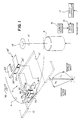
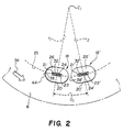
- FIG. 1 Details of a double-sided stabilizer device 4 are shown by Figures 1, 2 and 3.
- a magnetic disk 6 is enclosed for rotation within a jacket 10 (shown in broken-line in Figure 1) having an opening 12 through which the stabilizer device 4 can access both sides of the disk 6.
- a drive motor 8 has a spindle 13 connecting to a hub 14 that is securely attached to an inside periphery of the disk 6.
- Current for the motor 8 is supplied by a drive circuit 15, which is connected to a power supply 16.
- the motor 8 may be a brushless dc motor and the drive circuit 15 would provide electronic commutation of the motor.
- Feedback from a tachometer or like reference signal generator is provided to a speed controller circuit 17 for controlling the speed of the motor 8.
- the double-sided stabilizer device 4 includes a lower stabilizer device 18 and an upper stabilizer device 18'. (Since the stabilizer devices 18 and 18' are substantially identical except for their orientation, components of the upper device 18' will be designated with a prime (')).
- the stabilizer device 18 (18') includes a stabilizing block 20 (20') having an opening 22 (22') for exposing a magnetic head 24 (24') to the surface of the disk 6.
- a circumferential, flat air bearing surface 26 (26') surrounds the opening 22 (22') on the side of the block 20 (20') that faces the disk 6.
- the block 20 (20') is made of a hard ceramic material having a moderate degree of surface roughness-on the order of 10 ⁇ or greater as characterized by conventional root-mean-square measurement of surface height with a phase-shift interference microscope.
- the preferred material is a conductive barium titanate (BaTi03) available from Kyocera Corporation (Kyoto, Japan) as material item number T793H.
- the circumferential surface 26 (26') is shown to be oval in shape, other shapes are also believed to work in the practice of the invention.
- the stabilizer device is used in a system in which the heads 24 and 24' follow a circular trace 25 during recording and repeatedly follow the same trace 25 during reproduction.
- Each trace corresponds to a pair of tracks on opposite recording layers of the disk 6; for example, the paired tracks may correspond to a single video picture (e.g., a video field on opposite sides thereof) in a still video recording/reproduction system, or to video and audio in a still video system, or to data tracks in a data storage system.
- a single video picture e.g., a video field on opposite sides thereof
- video and audio in a still video system
- data tracks in a data storage system.
- the opening 22 (22') leads to a cavity 23 (23') in the block 20 (20').
- the head 24 (24') is mounted on the shoe 30 (30') to locate a magnetic gap 32 (32') in relation to the opening 22 (22') so that the gap 32 (32') slightly protrudes above the plane of the air bearing surface 26 (26').
- Figures 2 and 3 also show a step 21 (21') recessed about 0.005 inches below the air bearing surface 26 toward the edge of the opening 22 (22'). This step is believed to assist in the generation of coupling forces between the disk 6 and the head 24 (24'), as well as acting to at least somewhat reduce frictional drag and current draw on the drive motor.
- the stabilizing block 20 (20') is supported with respect to the disk 6 along a flat inclined surface 33 (33') of a wedge-shaped support 34 (34')-(or any other kind of like support)-mounted upon a conventional head positioning carriage (which is shown and later described in connection with Figure 6).
- the support 34 and thus the stabilizing block 20 are disposed at a particular angle (the attack angle) with respect to the nominal plane of the rotating disk.
- the nominal plane is the plane established by the rotating disk absent any interference.
- the other stabilizing block 20' which is downstream of the block 20 in relation to the moving disk 6, is disposed at an angle with respect to the plane of the disk 6 as it leaves the air bearing surface 26 of the block 20.
- the attack angle should be as small as possible to prevent excessive wear of the transducing and/or disk surfaces.
- the air bearing surface 26 is disposed at a negative angle of attack of 2.0° in relation to the nominal plane 40 of the disk 6.
- the air bearing surface 26' is disposed at an 0° angle with respect to the nominal plane 40, which places it at a negative attack angle of about 2.0° in relation to a disk region 40' just downstream of the air bearing surface 26.
- the edge-tracing radius r meets the air bearing surface 26 at an included angle 42 that is acute.
- the radius r is allowed to further trace a surface to point P', the point of joining with the flat surface 26a (parallel to surface 26) would be in tangential relation, that is, the line defined by the surface 26a would be tangent to the circle described by radius r.
- the leading edge 38 When the leading edge 38 is subjected to an abrupt transition at the point P, it can be seen that the air bearing surface 26 coincides with a chord PQ of the circle defined by the radius r.
- the perpendicular distance d of this chord PQ from the broken line surface 26' is between 0.0762 mm (0.003 inches and 0.127 mm (0.005 inches).
- the leading edge 38' of the stabilizing device 18' is configured the same as the leading edge 38 described in connection with Figure 4B.
- a stabilizer with the non-tangential transition P may be manufactured in any number of conventional ways.
- One way that works especially well is to manufacture a stabilizer of the type with a continuation of the blended radius leading edge 38a', as shown in Figure 4B, leading into the surface 26a. Then the surface 26a is lapped by conventional techniques until the lapped surface coincides with the air bearing surface 26 shown in Figure 4B. This requires removal of a thickness corresponding to the distance d, that is, between 0.0762 mm (0.003 inch) and 0.127 mm (0.005 inch).
- the transition point P is one of many points defining a curved line 44 that first meets the surface of the disk 6 as it is rotated over the penetrating leading edge 38 of the stabilizer 18. (The same is true of the stabilizer 18, though the corresponding curved line is hidden in the plan view of Figure 2.)
- This curved line 44 again shown as a point P in Figure 4A, serves as a fulcrum about which the contacting section of the disk 6 attempts to rotate. Though the precise mechanism is not well established, it is believed that a torque force is generated according to an arrow 46 ( Figure 4A) that attempts to twist the disk 6 clockwise. This force serves to deflect the disk 6 from its nominal plane 40 firmly upon the air bearing surface 26.
- each stabilizing device 18 and 18' is positioned in relation to separate radii r1 and r2 depending from the center c1 of the drive spindle.
- the stabilizing devices are separated by a circumferential offset 01 in the direction 36 of disk rotation.
- the amount of offset is empirically selected to permit the air bearing surfaces 26 and 26' to separately act upon the opposed surfaces of the disk 6 with a minimum level of interaction.
- no part of the air bearing surfaces 26 and 26' can be directly opposed such that they would be in contact in absence of the disk 6.
- the second stabilizing device 18' may need to be repositioned (relative to the position shown in Figure 3) so that the penetration of the leading edge 38' remains within acceptable limits.
- the stabilizing devices 18 and 18' and their included heads 24 and 24' may be mounted in any of several conventional configurations using conventional accessing mechanisms.
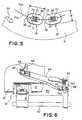
- One example is shown in Figure 6.
- a fragment of the magnetic disk 6 and its jacket 10 are shown with the opening 12 through which the dual heads 24 and 24' come in contact with the disk.
- the accessing mechanism includes a lower carriage 50 and a lead screw 52 (shown in broken line) or other type of radial accessing mechanism for driving the lower carriage 50 along the opening 12 to a selected radial track position.
- the first, or lower, stabilizing device 18 and its included head 24 are fixed to the free end of the lower carriage 50.
- the fixed stabilizing device 18 is positioned as shown in Figure 3 to penetrate or intercept the nominal plane 40 of the disk 6.
- a cantilevered upper carriage or load arm 54 is pivotally mounted at the end of the lower carriage 50.
- a small aperture 56 is provided adjacent the free end of the upper load arm 54, within which the upper stabilizing device 18' and its included head 24' are disposed facing toward the upper surface of the disk 6.
- a landing control tab 58 engageable by a solenoid operated element (not shown) to permit automatic pivoting of the load arm 54 away from the lower stabilizing device 18, as in the position shown in Figure 6, or to release the arm 54 to permit engagement or "landing" of the stabilizing device 18' on the magnetic disk 6 as shown in Figure 3.
- the base end of the load arm 54 is coupled to the adjacent end of the carriage 50 by a light flexure spring 60 which permits pivoting movement away from the stabilizing device 18.
- the spring 60 engages a head load stop 62 to define the limit for movement in the direction toward the fixed stabilizing device 18.
- a cylindrical mandrel 64 is coupled to the carriage adjacent the pivot end of the load arm 54 to spring load the arm 54 in the direction of the fixed stabilizing device 18.
- a keeper 68 on the end of the mandrel 64 maintains the load spring 66 in position once mounted.
- a typical mechanism of this type is disclosed in U.S. Patent No. 4,151,573.
- the movable, upper stabilizing device 18' is preferably fixed in the upper arm 54, rather than being gimbal-mounted, as shown in the patent. While gimbal mounting is not to be foreclosed, it is believed to be desirable to have the upper stabilizing device 18' fixed in relation to the nominal plane 40 of the disk 6 so that the penetration of the leading edge 38' can be tightly controlled.
- Another type of accessing mechanism that may be successful in this application is a "clamshell" mount in which both stabilizing devices 18 and 18' are mounted on pivotable arms that move toward and away from the magnetic disk. This type of mechanism is seen, for example, in U.S. Patent No. 3,946,439.
- Figure 5 shows the preferred application of two stabilizers in combination with dual gap heads.
- the stabilizers have openings 70 and 70' large enough to accommodate dual gap heads 72 and 72' for generating two traces 74a and 74b on each side of the disk 6.
- Figure 5 also shows a plan view of the 0.127 mm (0.005 inch) recess 21 (21') mentioned in connection with Figure 3.
- different types of head structure may be accommodated.
- Figure 5 shows an opening to a negative pressure cavity sufficient to contain the dual transducing gaps of a preferred thin-film head 72 (72') rather than a wound ferrite head.
Landscapes
- Supporting Of Heads In Record-Carrier Devices (AREA)
Abstract
Claims (9)
- Appareil destiné à accéder à deux faces d'un support souple de mémorisation (6) tournant autour d'un axe, l'appareil comprenant un premier et un second organe (50, 54) à chariot supporté (52) afin qu'il se déplace radialement par rapport audit axe, une paire de transducteurs (24, 24') supportés chacun par un organe respectif à chariot (50, 54), les transducteurs étant disposés sur des faces opposées du support de manière qu'un décalage circonférentiel (O₁) soit conservé entre les transducteurs (24, 24'), et
des dispositifs (20, 20') de stabilisation entourant des transducteurs respectifs (24, 24') et destinés à interagir avec le support de mémorisation (6) et à créer des forces respectives d'attraction sur des parties successives du support (6) d'entraînement en rotation lorsque chaque partie tourne près du dispositif de stabilisation, l'appareil étant caractérisé par
le décalage circonférentiel des transducteurs (24, 24') afin qu'aucune partie du dispositif de stabilisation (20) entourant un premier transducteur (24) ne soit directement opposée à une partie quelconque du dispositif de stabilisation (20') de l'autre transducteur (24'), et par
un dispositif (58) agissant sur l'un au moins des organes (54) de chariot et destiné à rappeler les transducteurs l'un vers l'autre afin que chaque transducteur interagisse séparément avec le support (6). - Appareil selon la revendication 1, dans lequel le premier organe (50) de chariot maintient l'un des transducteurs (24) en position fixe par rapport au support (6), et le second organe de chariot (54) supporte l'autre transducteur (24') afin qu'il se déplace en translation par rapport au support (6).
- Appareil selon la revendication 1, dans lequel les transducteurs (24, 24') sont décalés radialement par rapport à l'axe de rotation.
- Appareil selon la revendication 1, dans lequel les dispositifs respectifs de stabilisation (20, 20') qui entourent les transducteurs repoussent le support de mémorisation (6) par des faces opposées.
- Appareil selon la revendication 1, dans lequel les dispositifs de stabilisation comportent :
deux organes de stabilisation (20, 20') ayant chacun une surface (26, 26') de palier à air destinée à stabiliser le support de mémorisation (6) lorsqu'il tourne sur la surface,
un dispositif associé à chaque surface de palier à air et destiné à délimiter une cavité (23, 23') en dépression ayant une ouverture (22, 22') vers la surface (26, 26') afin qu'il crée une forme d'attraction sur des parties successives du support de mémorisation (6) lorsque chaque partie se déplace sur l'ouverture, et
un dispositif (30, 30') supportant un transducteur respectif (24, 24') dans la cavité (23, 23') d'un organe respectif de stabilisation (20, 20'). - Appareil selon la revendication 5, dans lequel les organes de stabilisation (20, 20') sont orientés afin que chaque surface (26, 26') de palier à air forme un angle négatif d'attaque (figure 3) par rapport au plan (40, 40') du support de mémorisation (6) à son point de rencontre avec chaque surface.
- Appareil selon la revendication 6, dans lequel les organes (20, 20') de stabilisation sont placés à distance de part et d'autre du support de mémorisation de manière qu'aucune partie des surfaces (26, 26') de palier à air ne soit directement opposée.
- Appareil selon la revendication 5, dans lequel les transducteurs (24, 24') sont des têtes (72, 72') à transducteurs ayant plusieurs entrefers transducteurs destinés à former simultanément des interfaces avec plusieurs pistes (74a, 74b) formées sur le disque.
- Appareil selon la revendication 5, dans lequel le dispositif (58) agissant sur l'un au moins des organes (54) à chariot repousse les transducteurs vers la position d'enregistrement (figure 3) avec une force d'amplitude suffisante pour que les organes de stabilisation (20, 20') fassent fléchir le support de mémorisation (6) par rapport à son plan nominal (40), si bien que le support est obligé de suivre les surfaces séparées (26, 26') des organes de stabilisation.
Applications Claiming Priority (2)
| Application Number | Priority Date | Filing Date | Title |
|---|---|---|---|
| US07/176,964 US4928196A (en) | 1988-04-04 | 1988-04-04 | Magnetic recording device using circumferentially offset heads with double sided media |
| US176964 | 1988-04-04 |
Publications (2)
| Publication Number | Publication Date |
|---|---|
| EP0363468A1 EP0363468A1 (fr) | 1990-04-18 |
| EP0363468B1 true EP0363468B1 (fr) | 1993-11-10 |
Family
ID=22646619
Family Applications (1)
| Application Number | Title | Priority Date | Filing Date |
|---|---|---|---|
| EP89904436A Expired - Lifetime EP0363468B1 (fr) | 1988-04-04 | 1989-03-30 | Dispositif d'enregistrement magnetique utilisant des tetes decalees de maniere circonferentielle a support a double face |
Country Status (5)
| Country | Link |
|---|---|
| US (1) | US4928196A (fr) |
| EP (1) | EP0363468B1 (fr) |
| JP (1) | JPH02504329A (fr) |
| DE (1) | DE68910635T2 (fr) |
| WO (1) | WO1989009987A1 (fr) |
Families Citing this family (7)
| Publication number | Priority date | Publication date | Assignee | Title |
|---|---|---|---|---|
| JP3587537B2 (ja) * | 1992-12-09 | 2004-11-10 | 株式会社半導体エネルギー研究所 | 半導体装置 |
| US5636085A (en) * | 1995-03-03 | 1997-06-03 | Iomega Corporation | Magnetic read/write head assembly configured with bleed slots passing through rails to stabilize flexible medium while attaining low fly heighs with respect thereto |
| US5942680A (en) * | 1997-04-22 | 1999-08-24 | Seagate Technology, Inc. | Multi-impact asperity sensor and burnish head |
| US6071007A (en) * | 1997-05-21 | 2000-06-06 | Seagate Technology, Inc. | Thermal asperity detection head |
| US6115219A (en) * | 1998-11-13 | 2000-09-05 | Iomega Corporation | Read write head assembly that has a pair of opposed sliders that each have a transverse slotted rail aligned with a rail in the opposing slider that does not have a transverse slotted rail |
| US6583959B1 (en) | 2000-09-19 | 2003-06-24 | Iomega Corporation | Read write head assembly having air bearing features for contaminant control in flexible media head-disk interface |
| US6947257B2 (en) * | 2001-07-11 | 2005-09-20 | Iomega Corporation | System and method of introducing a preferential curvature to a flexible medium for reduced medium vibration and sensor to medium spacing with a disk drive head stack assembly having a non-zero static roll attitude |
Family Cites Families (15)
| Publication number | Priority date | Publication date | Assignee | Title |
|---|---|---|---|---|
| JPS555954B1 (fr) * | 1968-08-14 | 1980-02-12 | ||
| US3946439A (en) * | 1975-01-31 | 1976-03-23 | International Business Machines Corporation | Recording apparatus for magnetic disks using both sides of the disk |
| GB1481370A (en) * | 1975-10-03 | 1977-07-27 | Burroughs Corp | Magnetic recording apparatus for recording on both sides of a moving record member |
| JPS5273709A (en) * | 1975-12-17 | 1977-06-21 | Hitachi Ltd | Magnetic disc device |
| US4003091A (en) * | 1976-03-08 | 1977-01-11 | International Business Machines Corporation | Transducer support and stabilizer |
| US4151573A (en) * | 1977-06-13 | 1979-04-24 | Tandon Magnetics Corp. | Magnetic recording device for double sided media |
| US4320426A (en) * | 1980-05-23 | 1982-03-16 | Xerox Corporation | Head assembly for recording on magnetic disc |
| US4537509A (en) * | 1982-03-10 | 1985-08-27 | Nortronics Company, Inc. | Optical inspection and alignment verification system |
| JPS5954071A (ja) * | 1982-09-22 | 1984-03-28 | Fujitsu Ltd | 磁気ヘツド安定支持装置 |
| US4578727A (en) * | 1984-02-27 | 1986-03-25 | Eastman Kodak Company | Device for stabilizing the movement of a floppy disk over a magnetic head |
| US4620250A (en) * | 1984-03-29 | 1986-10-28 | Eastman Kodak Company | Transducer-to-medium stabilizing device at negative attack angle with respect to medium |
| JPS6173268A (ja) * | 1984-09-17 | 1986-04-15 | Teac Co | 磁気デイスク装置 |
| JPS6252759A (ja) * | 1985-09-02 | 1987-03-07 | Matsushita Electric Ind Co Ltd | 磁気記録再生装置 |
| US4703375A (en) * | 1985-11-22 | 1987-10-27 | Chan Industries, Inc. | Low mass tricomplaint recording device for double sided floppy disk media |
| US4792874A (en) * | 1987-02-26 | 1988-12-20 | Eastman Kodak Company | Stabilizer device having an edge configuration for stabilizing the interface between a transducer and a moving medium |
-
1988
- 1988-04-04 US US07/176,964 patent/US4928196A/en not_active Expired - Lifetime
-
1989
- 1989-03-30 EP EP89904436A patent/EP0363468B1/fr not_active Expired - Lifetime
- 1989-03-30 JP JP1504348A patent/JPH02504329A/ja active Pending
- 1989-03-30 DE DE89904436T patent/DE68910635T2/de not_active Expired - Fee Related
- 1989-03-30 WO PCT/US1989/001283 patent/WO1989009987A1/fr not_active Ceased
Also Published As
| Publication number | Publication date |
|---|---|
| US4928196A (en) | 1990-05-22 |
| WO1989009987A1 (fr) | 1989-10-19 |
| EP0363468A1 (fr) | 1990-04-18 |
| JPH02504329A (ja) | 1990-12-06 |
| DE68910635D1 (de) | 1993-12-16 |
| DE68910635T2 (de) | 1994-05-11 |
Similar Documents
| Publication | Publication Date | Title |
|---|---|---|
| EP0218811B1 (fr) | Assemblage de glisseur pour têtes magnétiques | |
| US4151573A (en) | Magnetic recording device for double sided media | |
| EP0083932B1 (fr) | Appareil d'enregistrement/reproduction de signaux | |
| EP0346439B1 (fr) | Stabilisateur a faible resistance permettant de stabiliser l'interface entre un transducteur et un support en mouvement | |
| EP0372990A2 (fr) | Appareil d'enregistrement magnétique | |
| EP0363468B1 (fr) | Dispositif d'enregistrement magnetique utilisant des tetes decalees de maniere circonferentielle a support a double face | |
| CN1096675C (zh) | 滑块悬架组件和利用该组件的信息存储系统 | |
| US4367505A (en) | Magnetic head assembly with skewed read/write gap | |
| US6233120B1 (en) | Magnetic disk device | |
| EP0381741B1 (fr) | Dispositif a deux transduceurs en positions relatives fixes pour l'enregistrement magnetique sur deux faces | |
| EP0303671B1 (fr) | Dispositif stabilisateur ayant une configuration de bordure pour stabiliser l'interface entre un transducteur et un milieu mobile | |
| US4945436A (en) | Double-sided recording method using slanted guide plates upstream and downstream of recording heads | |
| JPH0485772A (ja) | 記録ディスク駆動装置 | |
| US4514772A (en) | Apparatus for reading/writing data on magnetic disc | |
| JPS6231076A (ja) | 磁気ヘツド構造体 | |
| JP2604420Y2 (ja) | 回転ヘッドドラム | |
| JPH0351805Y2 (fr) | ||
| JPS619818A (ja) | 磁気デイスク装置 | |
| JPS6220124A (ja) | 磁気デイスク装置 | |
| KR830000824B1 (ko) | 자기테이프 카세트 | |
| JPS6240680A (ja) | 磁気記録媒体 | |
| JPS619869A (ja) | 磁気記録再生装置 | |
| JPH02177014A (ja) | フロッピーディスク装置 | |
| JPH0527180B2 (fr) | ||
| JPS6194267A (ja) | 積層形可撓性デイスク装置の分離ブレ−ド |
Legal Events
| Date | Code | Title | Description |
|---|---|---|---|
| PUAI | Public reference made under article 153(3) epc to a published international application that has entered the european phase |
Free format text: ORIGINAL CODE: 0009012 |
|
| AK | Designated contracting states |
Kind code of ref document: A1 Designated state(s): BE DE FR GB NL |
|
| 17P | Request for examination filed |
Effective date: 19900330 |
|
| 17Q | First examination report despatched |
Effective date: 19920814 |
|
| RBV | Designated contracting states (corrected) |
Designated state(s): DE FR GB |
|
| GRAA | (expected) grant |
Free format text: ORIGINAL CODE: 0009210 |
|
| AK | Designated contracting states |
Kind code of ref document: B1 Designated state(s): DE FR GB |
|
| REF | Corresponds to: |
Ref document number: 68910635 Country of ref document: DE Date of ref document: 19931216 |
|
| ET | Fr: translation filed | ||
| PLBE | No opposition filed within time limit |
Free format text: ORIGINAL CODE: 0009261 |
|
| STAA | Information on the status of an ep patent application or granted ep patent |
Free format text: STATUS: NO OPPOSITION FILED WITHIN TIME LIMIT |
|
| 26N | No opposition filed | ||
| PGFP | Annual fee paid to national office [announced via postgrant information from national office to epo] |
Ref country code: GB Payment date: 19950217 Year of fee payment: 7 |
|
| PGFP | Annual fee paid to national office [announced via postgrant information from national office to epo] |
Ref country code: FR Payment date: 19950314 Year of fee payment: 7 |
|
| PGFP | Annual fee paid to national office [announced via postgrant information from national office to epo] |
Ref country code: DE Payment date: 19950330 Year of fee payment: 7 |
|
| PG25 | Lapsed in a contracting state [announced via postgrant information from national office to epo] |
Ref country code: GB Effective date: 19960330 |
|
| GBPC | Gb: european patent ceased through non-payment of renewal fee |
Effective date: 19960330 |
|
| PG25 | Lapsed in a contracting state [announced via postgrant information from national office to epo] |
Ref country code: FR Effective date: 19961129 |
|
| PG25 | Lapsed in a contracting state [announced via postgrant information from national office to epo] |
Ref country code: DE Effective date: 19961203 |
|
| REG | Reference to a national code |
Ref country code: FR Ref legal event code: ST |