EP0363699B1 - Appareil pour fermer des récipients - Google Patents
Appareil pour fermer des récipients Download PDFInfo
- Publication number
- EP0363699B1 EP0363699B1 EP89117438A EP89117438A EP0363699B1 EP 0363699 B1 EP0363699 B1 EP 0363699B1 EP 89117438 A EP89117438 A EP 89117438A EP 89117438 A EP89117438 A EP 89117438A EP 0363699 B1 EP0363699 B1 EP 0363699B1
- Authority
- EP
- European Patent Office
- Prior art keywords
- cover
- lid
- container
- containers
- slide
- Prior art date
- Legal status (The legal status is an assumption and is not a legal conclusion. Google has not performed a legal analysis and makes no representation as to the accuracy of the status listed.)
- Expired - Lifetime
Links
- 238000000034 method Methods 0.000 claims description 3
- 238000003825 pressing Methods 0.000 description 3
- 241001295925 Gegenes Species 0.000 description 2
- 230000008878 coupling Effects 0.000 description 2
- 238000010168 coupling process Methods 0.000 description 2
- 238000005859 coupling reaction Methods 0.000 description 2
- 230000008569 process Effects 0.000 description 2
- 230000009471 action Effects 0.000 description 1
- 230000015572 biosynthetic process Effects 0.000 description 1
- 238000005520 cutting process Methods 0.000 description 1
- 230000007423 decrease Effects 0.000 description 1
- 230000001419 dependent effect Effects 0.000 description 1
- 238000000151 deposition Methods 0.000 description 1
- 230000005484 gravity Effects 0.000 description 1
- 230000009191 jumping Effects 0.000 description 1
- 239000007788 liquid Substances 0.000 description 1
- 238000004519 manufacturing process Methods 0.000 description 1
- 230000007246 mechanism Effects 0.000 description 1
- 238000007789 sealing Methods 0.000 description 1
- 230000000087 stabilizing effect Effects 0.000 description 1
- 238000003860 storage Methods 0.000 description 1
- 230000001960 triggered effect Effects 0.000 description 1
Images

Classifications
-
- B—PERFORMING OPERATIONS; TRANSPORTING
- B65—CONVEYING; PACKING; STORING; HANDLING THIN OR FILAMENTARY MATERIAL
- B65B—MACHINES, APPARATUS OR DEVICES FOR, OR METHODS OF, PACKAGING ARTICLES OR MATERIALS; UNPACKING
- B65B7/00—Closing containers or receptacles after filling
- B65B7/16—Closing semi-rigid or rigid containers or receptacles not deformed by, or not taking-up shape of, contents, e.g. boxes or cartons
- B65B7/28—Closing semi-rigid or rigid containers or receptacles not deformed by, or not taking-up shape of, contents, e.g. boxes or cartons by applying separate preformed closures, e.g. lids, covers
- B65B7/2807—Feeding closures
-
- B—PERFORMING OPERATIONS; TRANSPORTING
- B67—OPENING, CLOSING OR CLEANING BOTTLES, JARS OR SIMILAR CONTAINERS; LIQUID HANDLING
- B67B—APPLYING CLOSURE MEMBERS TO BOTTLES JARS, OR SIMILAR CONTAINERS; OPENING CLOSED CONTAINERS
- B67B3/00—Closing bottles, jars or similar containers by applying caps
- B67B3/02—Closing bottles, jars or similar containers by applying caps by applying flanged caps, e.g. crown caps, and securing by deformation of flanges
- B67B3/06—Feeding caps to capping heads
- B67B3/062—Feeding caps to capping heads from a magazine
Definitions
- the invention relates to a device for closing containers in filling lines as described in the preamble of claim 1.
- lids on containers e.g. B. by allocation by means of screw spindles, in which the container stops under the stack of lids, and what applies only to round lids, the lid must be fixed to at least two, as a rule, three points and finally released at the same time so that it is in free fall finally lowered onto the container.
- the lid is different from the above. placed on a container moving on a conveyor, for which purpose it is fed from a magazine to the container via an inclined slide and, after being released, exits the inclined slide, is slipped over the front edge of the container and is pulled out or pulled by the moving container.
- the lid pushing device is already located above the lid, acting in the direction of its line of motion, directly at the point at which gravity and after the slide triggers the lid emerges from the incline and engages in the container rim (Roll) or an additional cover fixation from above (DE-A-24 55 900 and DD-B-90 314).
- the lid would be loaded with considerable pressure even when it was captured by the container before it was completely released from the chute, which can lead to a lid deformation, which is only followed by plastic lids without consequences.
- lid-container merging succeeds only with slip lids.
- slip lids include plastic push-on lids and screw-on lids. In principle, these are pulled out of the can from the inclined slide against friction by the can, where they are on standby.
- the release of the lid according to DD-B-90 314 is disadvantageous because here the mechanism locks each lid on the inclined slide twice and therefore these can no longer be supplied to the container in good time if the conveying sequence is too tight. In principle, the lid sequence hangs behind the container sequence, albeit slightly.
- the lids are not triggered when they meet the container, but are only pulled out of their spring-loaded locking by the mass of the pressure belt of the container standing securely on the conveyor belt. This means that each container takes its lid, i.e. the sequence of lids and the sequence of containers coincide.
- GB-A-727 764 shows a device for providing can covers with an unstacking device.
- the solution disclosed therein for feeding and placing the lid on the container works with a pivoting lever that holds a ready-made lid and, after the container has been identical, releases the lid on the pivoting lever for closing.
- the device has the disadvantage that the lid, with its significantly smaller diameter lying on the feeder, first lies against the pivoting lever and only then is the container brought into position on the pivoting lever. This creates uncertainties in the position of the cover; its constant and precise positioning cannot be achieved. Furthermore, the pivoting movements of the pivoting lever are too great and, due to their one-sidedness, lead to further positional uncertainties of the lid on the container.
- the object of the invention is to develop a device for closing containers with a push-in lid, in which the push-in lid, which slides out of a slope, which is preceded by a lid magazine to be unstacked, are allocated in such a way that they can fall without free fall, without deforming influence on an envelope curve sliding into the can opening, meet the same functionally reliable and form a closable lid-container unit by another device.
- two rotatable pawls are used on the lower segments of which the lid stack rests in the rest position and the flap lever, which is gripped by the filled container, carry out a small rotary movement and push the bottom lid away from these segments and by means of the upper segments reaching under the penultimate lid, the lid stack support.
- the rocker arm is released, the stack of lids is moved from the upper to the lower segment by means of spring return.
- a side shaft attached to a vertical shaft with a return spring Lock which performs a horizontal rotary movement in its solution, narrows the lid web in the locked position so that the front edge of the lid is locked a few millimeters above the can opening.
- the rocker arm on this shaft when it is caught by the filled container passing through, unlocks the bottom lid by turning it horizontally in the direction of transport of the can.
- the support roller is attached to a rocker which is oriented in the transport direction and can be lifted in the vertical direction. It is locked in the lower position in such a way that it counteracts the sliding of the cover when it is unlocked and when it springs out of the opening.
- the envelope curve of the cover that arises when the container is transported onwards is followed by the support roller and has a stabilizing effect on the cover layer.
- the mass of the support roller, its storage and arrangement ensure that only slight forces act on the cover and deformation is excluded.
- This lid-container unit is then fed to a press-in device.
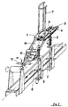
- FIG. 1 shows the overall view of the device
- FIGS. 2a and 2b the denester pawls.
- a filled container transported on the conveyor belt grasps the rocker arm 2 and rotates the shaft 3 with a return spring by approximately 15 °, as a result of which the rocker arm 4, which is connected to the pawls 6 via coupling elements 5, performs the same rotational movements and the lower segments 13 the pawls 6 unlock the bottom lid of the lid stack.
- the upper segments 14 of the pawls 6 slide under the penultimate cover and lock it.
- the released bottom cover falls into the chute 15, which has an angle of inclination to the container transport path of 30 to 35 ° and closes to the cover that is in standby. In this way, the container has already unstacked a lid for its subsequent one. As the container is transported further, it engages the rocker arm 8 of the shaft 9 with a return spring, thereby opening the lock 10 articulated on the shaft 9.
- the lid Since the opening path of the lock 10 runs parallel to the container transport path and the chute 15 form an angle of 30 to 35 ° to the two, the lid is unlocked after a very small rotation angle of the lock, so that the lid is immediately supported by the mass of the unlocked lid in the container transported a short distance below the lid, safely guided through the chute 15, slips against the front edge of the container opening.
- the opened lid covers a distance of approx. 6 mm after being folded down before it is locked.
- the lid is thus already in the transfer takeover position before the next cans reach the cover takeover position. In this way it is ensured that a cover is always in readiness for the cover of a tightly packed sequence of containers for the following container before it reaches the take-over position.
- the lid is normally not touched by the support roller 11, the axis of which is guided through the rocker 12 parallel to the container opening. It is adjusted so that only a possible jumping out of the lid from the can opening is prevented.
- the support roller 11 follows the envelope of the sliding lid and prevents the lid from tipping over.
Landscapes
- Engineering & Computer Science (AREA)
- Mechanical Engineering (AREA)
- Closing Of Containers (AREA)
- Electrical Discharge Machining, Electrochemical Machining, And Combined Machining (AREA)
- Vending Machines For Individual Products (AREA)
- De-Stacking Of Articles (AREA)
Claims (6)
- Dispositif destiné à fermer des récipients avec couvercles à enfoncer à l'intérieur, par rapprochement sur un plan de transport de récipients transportés avec couvercles, qui, provenant d'une pile de couvercles, par une glissière (15), sont amenés à un dispositif de blocage (10) et après passage du dispositif de blocage (10), sont centrés au-dessus de l'ouverture d'un récipient, afin d'être enfoncés dans le récipient, après un autre déplacement commun, une unité de dépilage et une unité de répartition étant prévues au-dessus d'une plaque de base (1), dans le sens de transport des récipients, caractérisé en ce que le dispositif de blocage (10) se trouve directement dans la zone latérale du couvercle, appliqué contre celui-ci, relié à un levier d'entraînement (8), mobile dans l'unité de distribution (9, 10, 11, 12), l'unité de distribution (9, 10, 11, 12) comportant dans la zone avant de sa glissière (15), en direction de son axe médian longitudinal, un bras oscillant (11) avec axe concentrique à l'extrémité duquel sont prévus, de part et d'autre, des rouleaux d'appui (12), qui suivent l'enveloppante du couvercle glissant sur ceux-ci et empêchent son basculement, après quoi, suivant le sens du transport des récipients, un dispositif d'enfoncement est prévu après le bras oscillant.
- Dispositif selon la revendication 1, caractérisé en ce que la glissière (15), dans le cas d'une longueur d'environ 3 diamètres de couvercle, forme un angle d'inclinaison d'au moins 30° par rapport à l'horizontale.
- Dispositif selon l'une des revendications précédentes, caractérisé en ce que le dispositif de blocage (10), qui maintient le couvercle avant sur le côté, est prévu directement devant sa plus grande extension, vers le bord latéral de la glissière (15).
- Dispositif selon les revendications 1 et 3, caractérisé en ce que l'angle de déviation du dispositif de biocage (10), destiné à faire glisser le couvercle sur le récipient, est compris entre 30° et 45°.
- Dispositif selon la revendication 2, caractérisé en ce que le bras oscillant (11) avec l'élément portant les rouleaux d'appui (12), est prévu de manière à se prolonger dans la direction d'extension de la glissière (15).
- Dispositif selon les revendications 1 à 5, caractérisé en ce que les rouleaux d'appui (12) peuvent être relevés verticalement au moyen du bras oscillant (11).
Priority Applications (1)
| Application Number | Priority Date | Filing Date | Title |
|---|---|---|---|
| AT89117438T ATE100399T1 (de) | 1988-09-21 | 1989-09-21 | Vorrichtung zum verschliessen von behaeltern. |
Applications Claiming Priority (2)
| Application Number | Priority Date | Filing Date | Title |
|---|---|---|---|
| DD319998 | 1988-09-21 | ||
| DD88319998A DD275650A1 (de) | 1988-09-21 | 1988-09-21 | Vorrichtung zum verschliessen von behaeltern in fuellinien |
Publications (2)
| Publication Number | Publication Date |
|---|---|
| EP0363699A1 EP0363699A1 (fr) | 1990-04-18 |
| EP0363699B1 true EP0363699B1 (fr) | 1994-01-19 |
Family
ID=5602573
Family Applications (1)
| Application Number | Title | Priority Date | Filing Date |
|---|---|---|---|
| EP89117438A Expired - Lifetime EP0363699B1 (fr) | 1988-09-21 | 1989-09-21 | Appareil pour fermer des récipients |
Country Status (4)
| Country | Link |
|---|---|
| EP (1) | EP0363699B1 (fr) |
| AT (1) | ATE100399T1 (fr) |
| DD (1) | DD275650A1 (fr) |
| DE (1) | DE58906757D1 (fr) |
Families Citing this family (1)
| Publication number | Priority date | Publication date | Assignee | Title |
|---|---|---|---|---|
| CN110498379A (zh) * | 2019-09-17 | 2019-11-26 | 邓杵娇 | 一种食品罐封盖装置 |
Family Cites Families (3)
| Publication number | Priority date | Publication date | Assignee | Title |
|---|---|---|---|---|
| GB727764A (en) * | 1953-02-03 | 1955-04-06 | Elgin Mfg Company | Improvements in or relating to feed mechanism for can covers |
| US2805532A (en) * | 1956-03-19 | 1957-09-10 | Ralph F Anderson | Cover applying apparatus |
| DE2550141C2 (de) * | 1975-11-07 | 1986-01-02 | Netzsch-Mohnopumpen Gmbh, 8672 Selb | Vorrichtung zum Aufsetzen von Deckeln auf Eimer, Dosen und ähnliche Behälter |
-
1988
- 1988-09-21 DD DD88319998A patent/DD275650A1/de not_active IP Right Cessation
-
1989
- 1989-09-21 DE DE89117438T patent/DE58906757D1/de not_active Expired - Fee Related
- 1989-09-21 AT AT89117438T patent/ATE100399T1/de not_active IP Right Cessation
- 1989-09-21 EP EP89117438A patent/EP0363699B1/fr not_active Expired - Lifetime
Also Published As
| Publication number | Publication date |
|---|---|
| EP0363699A1 (fr) | 1990-04-18 |
| DE58906757D1 (de) | 1994-03-03 |
| DD275650A1 (de) | 1990-01-31 |
| ATE100399T1 (de) | 1994-02-15 |
Similar Documents
| Publication | Publication Date | Title |
|---|---|---|
| DE2725134C2 (de) | Greifvorrichtung für das Ein- und Austragen von nach oben offenen Behältern | |
| EP0638501A1 (fr) | Dispositif convoyeur pour le transport ultérieur de produits plats, alimentés un par un | |
| DE3873075T2 (de) | Vorrichtung zum automatischen ausgeben von gegenstaenden. | |
| EP0150511B1 (fr) | Dispositif d'emballage d'objets, spécialement des cigarettes | |
| DE2461622C3 (de) | Vorrichtung zur Übergabe von Spinnhülsen | |
| DE3786746T2 (de) | Apparat zum transportieren und öffnen eines getränketrägers. | |
| DE2349608B2 (de) | Vorrichtung zum ausrichten von behaeltern | |
| DE3884780T2 (de) | Zuführvorrichtung für Büchsendeckel. | |
| DE3430943A1 (de) | Papierzufuehrungskassette | |
| EP3649626A1 (fr) | Dispositif et procédé de remplissage de contenants avec dde documents de valeur, en particulier des billets de banque, et système de traitement de documents de valeur | |
| EP0363699B1 (fr) | Appareil pour fermer des récipients | |
| DE3133341A1 (de) | "flaschen und aehnliche behaelter von einer abfuellmaschine zu einer verschliessmaschine transportierende einrichtung" | |
| DE2020470C3 (de) | Vorrichtung zum reihenweisen Einbringen von Gefäßen in Packbehälter | |
| EP1318958A1 (fr) | Procede et dispositif d'apport d'objets reguliers a une station de travail | |
| DE2127425B2 (de) | Vorrichtung zum selbsttätigen Aufsetzen von Kunststoff-Verschlüssen mit Hohlstopfen auf Behälter | |
| DE19822998C2 (de) | Vorrichtung zum Einbringen von gestapelten Kuverts in einen Transportkasten | |
| DE2415166C3 (de) | Vorrichtung zur Übergabe von ausgerichteten, konischen Hülsen an die Beschickungseinrichtung einer Spinnmaschine o.dgl | |
| EP0366955A1 (fr) | Dispositif pour poser des muselets | |
| DE102017115344A1 (de) | Vorrichtung und Verfahren zum Zuführen gefüllter und versiegelter Packungen an einen Applikator | |
| DE3875969T2 (de) | Vorrichtung zum oeffnen und schliessen einer filmkassette. | |
| DE102005003777B4 (de) | Vorrichtung zum Einschleusen von Behältern in freie Abschnitte eines Abschnittsförderers | |
| DE4131175C1 (fr) | ||
| CH677105A5 (fr) | ||
| EP0143138A1 (fr) | Dispositif pour la fermeture automatique de fermetures à rosace | |
| DE8916109U1 (de) | Vorrichtung zum Füllen und Verschließen von Dosen |
Legal Events
| Date | Code | Title | Description |
|---|---|---|---|
| PUAI | Public reference made under article 153(3) epc to a published international application that has entered the european phase |
Free format text: ORIGINAL CODE: 0009012 |
|
| AK | Designated contracting states |
Kind code of ref document: A1 Designated state(s): AT BE CH DE FR GB IT LI SE |
|
| 17P | Request for examination filed |
Effective date: 19900906 |
|
| RAP1 | Party data changed (applicant data changed or rights of an application transferred) |
Owner name: VEB FORSCHUNG UND RATIONALISIERUNG LACKE UND FARBE |
|
| RAP1 | Party data changed (applicant data changed or rights of an application transferred) |
Owner name: SCHROEDER, WOLFGANG |
|
| 17Q | First examination report despatched |
Effective date: 19911125 |
|
| GRAA | (expected) grant |
Free format text: ORIGINAL CODE: 0009210 |
|
| AK | Designated contracting states |
Kind code of ref document: B1 Designated state(s): AT BE CH DE FR GB IT LI SE |
|
| REF | Corresponds to: |
Ref document number: 100399 Country of ref document: AT Date of ref document: 19940215 Kind code of ref document: T |
|
| REF | Corresponds to: |
Ref document number: 58906757 Country of ref document: DE Date of ref document: 19940303 |
|
| GBT | Gb: translation of ep patent filed (gb section 77(6)(a)/1977) |
Effective date: 19940210 |
|
| ITF | It: translation for a ep patent filed | ||
| ET | Fr: translation filed | ||
| PLBE | No opposition filed within time limit |
Free format text: ORIGINAL CODE: 0009261 |
|
| STAA | Information on the status of an ep patent application or granted ep patent |
Free format text: STATUS: NO OPPOSITION FILED WITHIN TIME LIMIT |
|
| 26N | No opposition filed | ||
| EAL | Se: european patent in force in sweden |
Ref document number: 89117438.5 |
|
| PGFP | Annual fee paid to national office [announced via postgrant information from national office to epo] |
Ref country code: GB Payment date: 19970918 Year of fee payment: 9 |
|
| PGFP | Annual fee paid to national office [announced via postgrant information from national office to epo] |
Ref country code: BE Payment date: 19970924 Year of fee payment: 9 |
|
| PGFP | Annual fee paid to national office [announced via postgrant information from national office to epo] |
Ref country code: SE Payment date: 19970926 Year of fee payment: 9 Ref country code: FR Payment date: 19970926 Year of fee payment: 9 |
|
| PGFP | Annual fee paid to national office [announced via postgrant information from national office to epo] |
Ref country code: CH Payment date: 19970929 Year of fee payment: 9 |
|
| PGFP | Annual fee paid to national office [announced via postgrant information from national office to epo] |
Ref country code: AT Payment date: 19970930 Year of fee payment: 9 |
|
| PGFP | Annual fee paid to national office [announced via postgrant information from national office to epo] |
Ref country code: DE Payment date: 19971009 Year of fee payment: 9 |
|
| PG25 | Lapsed in a contracting state [announced via postgrant information from national office to epo] |
Ref country code: GB Free format text: LAPSE BECAUSE OF NON-PAYMENT OF DUE FEES Effective date: 19980921 Ref country code: AT Free format text: LAPSE BECAUSE OF NON-PAYMENT OF DUE FEES Effective date: 19980921 |
|
| PG25 | Lapsed in a contracting state [announced via postgrant information from national office to epo] |
Ref country code: SE Free format text: LAPSE BECAUSE OF NON-PAYMENT OF DUE FEES Effective date: 19980922 |
|
| PG25 | Lapsed in a contracting state [announced via postgrant information from national office to epo] |
Ref country code: LI Free format text: LAPSE BECAUSE OF NON-PAYMENT OF DUE FEES Effective date: 19980930 Ref country code: CH Free format text: LAPSE BECAUSE OF NON-PAYMENT OF DUE FEES Effective date: 19980930 Ref country code: BE Free format text: LAPSE BECAUSE OF NON-PAYMENT OF DUE FEES Effective date: 19980930 |
|
| BERE | Be: lapsed |
Owner name: SCHRODER WOLFGANG Effective date: 19980930 |
|
| GBPC | Gb: european patent ceased through non-payment of renewal fee |
Effective date: 19980921 |
|
| REG | Reference to a national code |
Ref country code: CH Ref legal event code: PL |
|
| EUG | Se: european patent has lapsed |
Ref document number: 89117438.5 |
|
| PG25 | Lapsed in a contracting state [announced via postgrant information from national office to epo] |
Ref country code: FR Free format text: LAPSE BECAUSE OF NON-PAYMENT OF DUE FEES Effective date: 19990531 |
|
| PG25 | Lapsed in a contracting state [announced via postgrant information from national office to epo] |
Ref country code: DE Free format text: LAPSE BECAUSE OF NON-PAYMENT OF DUE FEES Effective date: 19990701 |
|
| REG | Reference to a national code |
Ref country code: FR Ref legal event code: ST |
|
| PG25 | Lapsed in a contracting state [announced via postgrant information from national office to epo] |
Ref country code: IT Free format text: LAPSE BECAUSE OF NON-PAYMENT OF DUE FEES;WARNING: LAPSES OF ITALIAN PATENTS WITH EFFECTIVE DATE BEFORE 2007 MAY HAVE OCCURRED AT ANY TIME BEFORE 2007. THE CORRECT EFFECTIVE DATE MAY BE DIFFERENT FROM THE ONE RECORDED. Effective date: 20050921 |