EP0363717B1 - Oszillierende Rasensprenger - Google Patents
Oszillierende Rasensprenger Download PDFInfo
- Publication number
- EP0363717B1 EP0363717B1 EP89117677A EP89117677A EP0363717B1 EP 0363717 B1 EP0363717 B1 EP 0363717B1 EP 89117677 A EP89117677 A EP 89117677A EP 89117677 A EP89117677 A EP 89117677A EP 0363717 B1 EP0363717 B1 EP 0363717B1
- Authority
- EP
- European Patent Office
- Prior art keywords
- sleeve
- water
- driving mechanism
- mechanism box
- spray pipe
- Prior art date
- Legal status (The legal status is an assumption and is not a legal conclusion. Google has not performed a legal analysis and makes no representation as to the accuracy of the status listed.)
- Expired - Lifetime
Links
Images


Classifications
-
- B—PERFORMING OPERATIONS; TRANSPORTING
- B05—SPRAYING OR ATOMISING IN GENERAL; APPLYING FLUENT MATERIALS TO SURFACES, IN GENERAL
- B05B—SPRAYING APPARATUS; ATOMISING APPARATUS; NOZZLES
- B05B3/00—Spraying or sprinkling apparatus with moving outlet elements or moving deflecting elements
- B05B3/02—Spraying or sprinkling apparatus with moving outlet elements or moving deflecting elements with rotating elements
- B05B3/04—Spraying or sprinkling apparatus with moving outlet elements or moving deflecting elements with rotating elements driven by the liquid or other fluent material discharged, e.g. the liquid actuating a motor before passing to the outlet
- B05B3/0417—Spraying or sprinkling apparatus with moving outlet elements or moving deflecting elements with rotating elements driven by the liquid or other fluent material discharged, e.g. the liquid actuating a motor before passing to the outlet comprising a liquid driven rotor, e.g. a turbine
- B05B3/0432—Spraying or sprinkling apparatus with moving outlet elements or moving deflecting elements with rotating elements driven by the liquid or other fluent material discharged, e.g. the liquid actuating a motor before passing to the outlet comprising a liquid driven rotor, e.g. a turbine the rotation of the outlet elements being reversible
- B05B3/0438—Tubular elements holding several outlets, e.g. apertured tubes, oscillating about an axis substantially parallel to the tubular element
Definitions
- the invention relates to an oscillating lawn sprinkler which is capable to be freely placed on the ground and to be connected with a water supply source in view of irrigating tilled areas such as lawns, gardens, etc.
- a sprinkler of this type basically consists of a pipe featuring a number of spray perforations or nozzles, pivotally mounted on a bearing block and driven by the water pressure through a turbine-type motor enclosed in a sealed box.
- the bearing block usually has a longitudinally extended shape, while the box containing the driving mechanism is mounted in correspondence of one of its ends in such a way as to be connected with the water supply source and, at the same time, act as a driving support for at least one of the ends of the oscillating pipe.
- Mechanical control means are furthermore provided in the box containing the driving mechanism, which can be used to selectively confine the surface of the area to be watered.
- control means are generally mounted on the inner side, ie. the one looking towards the spraying pipe, of the box containing the driving mechanism, just below the end part of the spraying pipe itself.
- sprinklers in general can be connected to water supply sources which are different from a drinking water supply conduit. For instance, they can be supplied with water from open irrigation canal through proper delivery pumps.
- a filtering device to retain all such particulate contaminants and foreign matters as may be delivered with the water, which are likely to damage the turbine-like driving mechanism of the sprinkler.
- a strainer is usually inserted at the end side of the water supply hose which has to be connected with the water supply intake fitting of the sprinkler by means of a ring nut.
- strainer is again quite unconvenient in that it makes it rather difficult to clean its filtering surface when it becomes clogged.
- the strainer is quite often fitted in a fixed way in the end fitting of the water supply hose and, in all cases where it can be removed, it becomes necessary to disassemble the whole fitting in order to be able to clean its filtering surface.
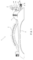
- the sprinkler 4 shown in the Figures includes a bearing block 5 which supports the driving mechanism box 6 and the oscillating spray pipe 7.
- the driving mechanism box 6 is of a traditional water-pressure type and includes all such components as required to operate the spray pipe 7 (eg. the turbine-like motor, the mechanism to adjust the oscillating range of the spray type, etc.), which are already well-known and therefore do not require any further description. It should be sufficient here to remember that the sprinkler 4 is operated by the pressure that the water flowing into the driving mechanism box 6, through the inlet connection 8, imparts on the blades of a turbine-like motor which is mechanically linked with the spray pipe 7.
- the spray pipe 7 eg. the turbine-like motor, the mechanism to adjust the oscillating range of the spray type, etc.
- said driving mechanism box 6 is already duly fitted with both the afore mentioned device to adjust the oscillating range of the spray pipe 7, through the actuation of the control knob 9, and a suitable device to further adjust the flow rate of the water delivered by the spray pipe 7 itself.
- Said water-flow adjusting device comprises a sleeve 10 ⁇ which is pressed through two pipe unions 11, 12 (Fig.3) that are provided in the wall of the driving mechanism box 6.
- Said sleeve 10 ⁇ is provided with annular grooves 13, 14 to accomodate corresponding sealing rings 15, 16 and it features two opposed openings (only one opening 17 is shown in Fig. 3) having an elongate shape and capable of letting the supply water flow from the driving mechanism box 6 to the spray pipe 7.
- the open end of the spray pipe 7 is attached by pressure fitting to the inwardly facing end of the sleeve 10 ⁇ .
- an inner annular groove 18, an axial projection 19 and a cylindrical housing 20 ⁇ which is arranged externally to the sleeve 10 ⁇ and coaxially with respect to the latter (fig.3), are obtained, all of which are capable to co-operate with a valve 21 for adjusting the water delivery rate.
- Said valve 21 is essentially formed by a stem 22, on the inner end of which two opposed tabs 23, 24 are provided which are capable to throttle the water passage openings 17.
- valve stem 22 The outer end of the valve stem 22 is provided with a retaining collar 25 and an adjustment knob 26.
- Said valve 21 is simply fitted into the sleeve 10 ⁇ , where it is retained by its collar 25 engaging as a spring latch into the afore mentioned groove 18 of the sleeve 10 ⁇ , as well as by two spring tabs 27, 28 which are capable to co-operate with the inner edge of the pipe union 12 in order to prevent the sleeve 10 ⁇ to be accidentally extracted from the driving mechanism box 6.
- the throttling tabs 23, 24 of the valve 21 show a surface which is tapered toward their free end in order to enable also small flow-rate variations to be accomplished.
- said tabs 23, 24 can be rotated over the whole range between two extreme settings, ie. for full and minimum water flow-rate repectively, in correspondence of each one of them a radial projection 29 of the knob 26 strikes against the longitudinal edges of the afore mentioned axial projection 19 of the sleeve 10 ⁇ , thereby creating corresponding positive limit stops.
- the device provided for adjusting the oscillating range of the spray pipe 7 is essentially of a known type, except for its being peculiarly arranged on that side of the driving mechanism box 6 which is opposed to the one where the end of the spray pipe 7 is connected, as well as its being mechanically linked with the previously described sleeve 10 ⁇ .
- a flange 30 ⁇ is integrally obtained which is capable of linking the device for the adjustment of the oscillating range (knob 9 and linking rods connected with it) with the sleeve 10 ⁇ supporting one end of the spray pipe 7.
- the sprinkler according to the present invention is designed in such a way as to allow for a more convenient arrangement of the water filtering device inside the pipe union 8 provided for the connection of the water supply hose.
- said pipe union 8 is made in the form of a "male-type” connection fitting (Fig.3) to be snap-fitted into a corresponding "female-type” fitting attached to the end of the water supply hose (not shown in the Figures).
- a counterbore 31 is provided inside the hose-connection fitting 8 , against which the open edge 32 of a cartridge strainer 33 can rest.
- This cartridge strainer can therefore be inserted in an easily removable way into the water supply conduit of the sprinkler itself (Fig.1).
- connection fitting 8 two longitudinal bevel cuts 34, 35 (Fig.2) are provided on the inner surface of the connection fitting 8, which are capable to allow, through the insertion of any kind of suitably pointed tool, for easy removal of said filtering cartridge 33 and, as a consequence, convenient removal of all particulate contaminants and foreign matters retained by the cartridge itself.
- the objects of the invention can be considered as fully reached through the provision of a device for adjusting the water delivery flow-rate, as well as through the arrangement of all user controls of the sprinkler on a much more convenient location.
- the object is furthermore reached of obtaining a water filtering device which is made independent of any part or component outside the sprinkler itself and is housed in an easily removable way inside the water supply conduit of the sprinkler.
Landscapes
- Nozzles (AREA)
- Special Spraying Apparatus (AREA)
Claims (9)
- Oszillierender Rasensprenger mit einem Tragrahmen (5), auf dem ein um eine Horizontalachse schwenkendes und mit Spritzdüsen (7) versehenes Berieselungsrohr aufgebracht ist, wobei dieses Berieselungsrohr vom Wasserdruck durch ein wasserturbinenähnlichen Triebwerk schwenkend angetrieben wird, das in einem wasserdichten, auf der einen Seite an die Wasserversorgungsleitung und auf der anderen Seite an einen der beiden Endteile des Berieselungsrohres angeschlossenen Antriebsgehäuse (6) untergebracht ist und zur Steuerung des Berieselungsrohres derart dient, daß es das genannte Berieselungsrohr um eine solche Winkelbewegung oder durch einen solchen Schwenkbereich schwenkt, wie sie durch in Verbund mit dem genannten Antriebsgehäuse vorgesehene Stellmittel einstellbar sind, wobei das genannte Antriebsgehäuse (6) Mittel (21) zum Einstellen des vom Berieselungsrohr (7) gelieferten Wasserdurchflusses umfaßt, dadurch gekennzeichnet, daß die genannten Stellmittel (21) für den vom Berieselungsrohr gelieferten Wasserdurchfluß und die genannten Stellmittel für den Schwenkbereich des Berieselungsrohres (7) zusammen mit den zugehörigen Betätigungsmitteln (26, 9) , sowie zusammen mit für das Zuleitungswasser vorgesehenen Filtriermitteln (33), auf der Gegenseite der mit einem Endteil des Berieselungsrohres (7) verbundenen Seite des Antriebsgehäuses (6) angeordnet sind.
- Oszillierender Rasensprenger nach Anspruch 1, dadurch gekennzeichnet, daß die genannten Stellmittel für die vom Berieselungsrohr (7) gelieferte Wasserdurchflußmenge ein mit einer Röhrenmuffe (10) kommunizierendes Ventil (21) umfassen, wobei diese Röhrenmuffe (10) dicht durch das Antriebsgehäuse (6) eingeführt und mit öffnungen (17) versehen ist, die mit der Innenseite des genannten Antriebsgehäuses (6) kommunizieren, wobei ein Endteil der genannten Röhrenmuffe (10) mit dem schwenkenden Berieselungsrohr (7) verbunden ist und der andere Endteil der genannten Röhrenmuffe (10) das genannte Ventil (21) aufnimmt, das imstande ist, das Wasserdurchfluß durch solche öffnungen (17) zu begrenzen.
- Oszillierender Rasensprenger nach den vorhergehenden Ansprüchen 1 oder 2, dadurch gekennzeichnet, daß das genannte Ventil (21) einen Schaft (22) umfaßt, der koaxial in der Röhrenmuffe (10) eingeführt und dort frei um einen solchen Winkel beweglich angebracht ist, der etwa der wirlichen Lichtweite der öffnungen (17) entspricht, wobei der innere Endteil des genannten Schafts (22) mit mindestens zwei Flügeln, die imstande sind, die die Wasserströmung durch die Röhrenmuffe (10) sichernden öffnungen (17) zu drosseln, und der äußere Endteil des genannten Schafts (22) sowohl mit Mitteln (25) zum Eingreifen mit der Röhrenmuffe (10) als auch mit Betätigungsmitteln (26, 29), die mit entsprechenden, in der Röhrenmuffe (10) vorgesehenen Rückhalte- bzw. Rotationsbegrenzungsmitteln (18, 9) zusammenwirken können, versehen sind.
- Oszillierender Rasensprenger nach den vorhergehenden Ansprüchen von 1 bis 3, dadurch gekennzeichnet, daß die genannten, zum Eingreifen des Schafts (22) mit der Röhrenmuffe (10) vorgesehenen Mittel in der Form eines Kragens (25) gestaltet sind, der zum Einklinken in eine entsprechende, an der Innenseite der Röhrenmuffe (10) herausgewonnene Ringnut (18) gedrückt werden kann, und daß die genannten Betätigungsmittel in der Form eines mit einem radialen Vorsprung (29) versehenen Knopfes (26) gestaltet sind, wobei der genannte radiale Vorsprung (29) zur Begrenzung des Rotationswinkels des Ventils (21) gegen die aüßeren Ränder eines axialen Vorsprung (19) der Röhrenmuffe (10) in Anschlag gebracht werden kann.
- Oszillierender Rasensprenger nach den vorhergehenden Ansprüchen von 1 bis 4, dadurch gekennzeichnet, daß die genannten Drosselungsflügel (23, 24) des Ventils (21) ein verjüngtes Flächenbild aufweisen.
- Oszillierender Rasensprenger nach den vorhergehenden Ansprüchen von 1 bis 5, dadurch gekennzeichnet, daß die genannte Röhrenmuffe (10) mechanisch mit der zum Einstellen des Schwenkbereichs des Berieselungsrohres vorgesehenen Vorrichtung mittels eines am äußeren Ende der Röhrenmuffe (10) einstückig damit geformten Flansches (30) in Verbindung steht.
- Oszillierender Rasensprenger nach Anspruch 1, worin das genannte Antriebsgehäuse an die Wasserzuleitung unter Zwischenschaltung von Filtriermitteln für die Zuleitungswasser angeschlossen ist, dadurch gekennzeichnet, daß die genannten Filtriermittel (33) für die Zuleitungswasser in dem genannten Antriebsgehäuse (6) entfernbar untergebracht sind.
- Oszillierender Rasensprenger nach Anspruch 7, dadurch gekennzeichnet, daß die genannten Filtriermittel aus einem Korb-, Käfig- oder ähnlichen Schmutzfänger (33) besteht, der auf der Einlaufseite des Wasserzuleitungsstutzens (8) des Antriebsgehäuses (6) entfernbar angeordnet ist.
- Oszillierender Rasensprenger nach Anspruch 8, dadurch gekennzeichnet, daß der genannte Wasserzuleitungsstutzen (8) in seinem Innern mit einer als Anschlag für den offenen Rand (32) des Schmutzfängerkorbs (33) dienenden Stoßfläche (31) versehen ist und auf seiner inneren Fläche einen oder mehrere Kerbschnitte (35, 35) zeigt, die zur leichten Entfernung des Schmutzfängerkorbs (33) aus seinem Sitz (31) unter Einstecken eines geeigneten spitz zulaufenden Werkzeug vorgesehen sind.
Applications Claiming Priority (2)
| Application Number | Priority Date | Filing Date | Title |
|---|---|---|---|
| IT3404988U | 1988-10-14 | ||
| IT8834049U IT218185Z2 (it) | 1988-10-14 | 1988-10-14 | Irroratore oscillante perfezionato. |
Publications (3)
| Publication Number | Publication Date |
|---|---|
| EP0363717A2 EP0363717A2 (de) | 1990-04-18 |
| EP0363717A3 EP0363717A3 (en) | 1990-11-07 |
| EP0363717B1 true EP0363717B1 (de) | 1994-03-09 |
Family
ID=11239035
Family Applications (1)
| Application Number | Title | Priority Date | Filing Date |
|---|---|---|---|
| EP89117677A Expired - Lifetime EP0363717B1 (de) | 1988-10-14 | 1989-09-25 | Oszillierende Rasensprenger |
Country Status (5)
| Country | Link |
|---|---|
| US (1) | US5033678A (de) |
| EP (1) | EP0363717B1 (de) |
| DE (1) | DE68913645T2 (de) |
| ES (1) | ES2052854T3 (de) |
| IT (1) | IT218185Z2 (de) |
Cited By (2)
| Publication number | Priority date | Publication date | Assignee | Title |
|---|---|---|---|---|
| US7419105B2 (en) | 2005-11-30 | 2008-09-02 | Yuan Mei Corp. | Spray oscillating control apparatus for sprinklers |
| US7422162B2 (en) | 2005-11-30 | 2008-09-09 | Yuan Mei Corp. | Automatic water inlet switching device for an oscillating sprinkler |
Families Citing this family (18)
| Publication number | Priority date | Publication date | Assignee | Title |
|---|---|---|---|---|
| IT236574Y1 (it) * | 1995-01-03 | 2000-08-17 | Claber Spa | Dispositivo di trasmissione del moto ad un braccio oscillante di un irrigatore |
| USD398952S (en) | 1997-10-27 | 1998-09-29 | Mei-Hsueh Hsueh | Sprinkler |
| IT1311205B1 (it) | 1999-02-22 | 2002-03-04 | Uniflex Utiltime Spa | Irroratore con getti regolabili |
| DE20012841U1 (de) | 2000-07-25 | 2001-03-08 | Zens, Hans-Peter, 56626 Andernach | Sprinkleranlage zur Bewässerung von Grünflächen |
| IL157660A0 (en) | 2003-08-29 | 2004-03-28 | Elgo Irrigation Ltd | Oscillating sprinkler with a self contained fertilizing unit and method of applying fertilizer with the same |
| US7624934B2 (en) * | 2005-02-02 | 2009-12-01 | Robert Bosch Tool Corporation | Wind resistant oscillating sprinkler |
| US7607590B2 (en) * | 2006-08-31 | 2009-10-27 | Melnor, Inc. | Oscillating sprinkler with adjustable spray width |
| US7883033B2 (en) * | 2007-12-10 | 2011-02-08 | Battelle Memorial Institute | Lead screw locking device |
| US7942347B2 (en) * | 2008-01-02 | 2011-05-17 | Yuan Pin Industrial Co., Ltd. | Sprinkler having oscillating mechanism |
| US9440250B2 (en) * | 2009-12-18 | 2016-09-13 | Rain Bird Corporation | Pop-up irrigation device for use with low-pressure irrigation systems |
| USD652484S1 (en) | 2011-04-08 | 2012-01-17 | Melnor, Inc. | Sprinkler base unit |
| USD652486S1 (en) | 2011-04-08 | 2012-01-17 | Melnor, Inc. | Sprinkler base unit |
| USD652485S1 (en) | 2011-04-08 | 2012-01-17 | Melnor, Inc. | Sprinkler base unit |
| USD652483S1 (en) | 2011-04-08 | 2012-01-17 | Melnor, Inc. | Sprinkler base unit |
| DE202011104874U1 (de) | 2011-08-27 | 2011-10-27 | Silag Handel Ag | Flächen-, Rechteck- oder Viereckregner als Beregnungsvorrichtung |
| US10667475B2 (en) | 2014-11-06 | 2020-06-02 | E-Z Flush Filters, Llc | Irrigation filter system |
| CN108176533B (zh) * | 2017-11-24 | 2019-06-25 | 浙江杭重科技有限公司 | 一种轴承自动化涂油装置 |
| CN116897806B (zh) * | 2023-07-28 | 2026-02-24 | 中山市庆谊金属制品企业有限公司 | 一种防沙的洒水器机构 |
Family Cites Families (17)
| Publication number | Priority date | Publication date | Assignee | Title |
|---|---|---|---|---|
| US2693390A (en) * | 1951-09-04 | 1954-11-02 | Scovill Manufacturing Co | Lawn sprinkler |
| US2942789A (en) * | 1958-03-26 | 1960-06-28 | Lloyd B Smith | Sprinkler |
| GB907291A (en) * | 1958-07-21 | 1962-10-03 | John Huggan And Co Ltd | Improvements in or relating to oscillation mechanisms for irrigation lines |
| US3105639A (en) * | 1960-08-31 | 1963-10-01 | Sunbeam Corp | Lawn sprinkler |
| US3055595A (en) * | 1960-11-09 | 1962-09-25 | Turner Corp | Oscillatory lawn sprinkler |
| US3270963A (en) * | 1962-04-18 | 1966-09-06 | Sunbeam Corp | Lawn sprinkler |
| US3212752A (en) * | 1963-04-15 | 1965-10-19 | Gen Electric | Fluid pressure and spring biased sealed flow control valve |
| US3175770A (en) * | 1963-08-26 | 1965-03-30 | Head & Johnson | Lawn sprinkler |
| US3559888A (en) * | 1968-11-18 | 1971-02-02 | Louis F Miklos | Lawn sprinkler with flexible nozzle |
| DE1912315B1 (de) * | 1969-03-11 | 1970-10-08 | Kupex Ag | Beregnungsvorrichtung |
| US3567122A (en) * | 1969-07-16 | 1971-03-02 | Western Ind Inc | Water sprinkler having counter means for an oscillating distributing tube of uniform speed |
| US3645451A (en) * | 1970-08-24 | 1972-02-29 | Fred Hauser | Sprinkler device |
| IT7822941U1 (it) * | 1978-10-03 | 1980-04-03 | Claber Spa | Irrigatore a braccio oscillante per prati, campi, giardini e terreni coltivati in genere |
| US4245786A (en) * | 1979-04-16 | 1981-01-20 | Abrahamsen Johan E | Oscillating lawn spray with variable width and length |
| IL68597A (en) * | 1983-05-05 | 1988-03-31 | Rinkewich Isaac | Multiple chamber sprinkler |
| US4721248A (en) * | 1986-04-14 | 1988-01-26 | Jet Stream, Inc. | Readily assembleable oscillating sprinkler |
| US4860954A (en) * | 1987-04-20 | 1989-08-29 | Rain Bird Consumer Products Mfg. Corp. | Adjustable oscillating wave-type sprinkler |
-
1988
- 1988-10-14 IT IT8834049U patent/IT218185Z2/it active
-
1989
- 1989-09-25 ES ES89117677T patent/ES2052854T3/es not_active Expired - Lifetime
- 1989-09-25 DE DE68913645T patent/DE68913645T2/de not_active Expired - Fee Related
- 1989-09-25 EP EP89117677A patent/EP0363717B1/de not_active Expired - Lifetime
- 1989-10-13 US US07/427,685 patent/US5033678A/en not_active Expired - Fee Related
Cited By (2)
| Publication number | Priority date | Publication date | Assignee | Title |
|---|---|---|---|---|
| US7419105B2 (en) | 2005-11-30 | 2008-09-02 | Yuan Mei Corp. | Spray oscillating control apparatus for sprinklers |
| US7422162B2 (en) | 2005-11-30 | 2008-09-09 | Yuan Mei Corp. | Automatic water inlet switching device for an oscillating sprinkler |
Also Published As
| Publication number | Publication date |
|---|---|
| DE68913645D1 (de) | 1994-04-14 |
| EP0363717A2 (de) | 1990-04-18 |
| IT8834049V0 (it) | 1988-10-14 |
| US5033678A (en) | 1991-07-23 |
| ES2052854T3 (es) | 1994-07-16 |
| EP0363717A3 (en) | 1990-11-07 |
| IT218185Z2 (it) | 1992-04-08 |
| DE68913645T2 (de) | 1994-07-14 |
Similar Documents
| Publication | Publication Date | Title |
|---|---|---|
| EP0363717B1 (de) | Oszillierende Rasensprenger | |
| US6840460B2 (en) | Rotor type sprinkler with insertable drive subassembly including horizontal turbine and reversing mechanism | |
| US6568608B2 (en) | Water sprinkler head with integral off-on water flow control valve and adaptive fittings therefor | |
| US7040553B2 (en) | Rotor type sprinkler with reversing mechanism including sliding clutch and driven bevel gears | |
| US6799732B2 (en) | Water sprinkler head with integral off-on water flow control valve and adaptive fittings therefor | |
| US6827298B2 (en) | Adjustable flow bubbler for drip irrigation systems | |
| EP2251090A2 (de) | Sprinklervorrichtung mit variabler Reichweite und Verfahren für Muster für Sprinkler mit variabler Reichweite | |
| US7090146B1 (en) | Above-ground adjustable spray pattern sprinkler | |
| AU757521B2 (en) | Closed-case impact sprinklers | |
| AU678860B2 (en) | Multifunction delivery unit for irrigation pistol | |
| US3303800A (en) | Soil conditioning apparatus | |
| US2460407A (en) | Washer for garden hose couplings | |
| US20050194464A1 (en) | Adjustable sprinkler | |
| CA2135962C (en) | Adjustable spray system and assembly method | |
| US4848661A (en) | Sprinkler head shutoff valve | |
| US3535862A (en) | Cleaning attachment for mower | |
| US4762278A (en) | Combination lawn mower washer and sharpener | |
| US7743786B2 (en) | Irrigation system and shut-off control device therefor | |
| US5042719A (en) | Oscillating lawn sprinkler | |
| US7066403B2 (en) | Sprinkling system and method | |
| US6302335B1 (en) | Lawn sprinkler system | |
| EP0630555A1 (de) | Sprinkleraufbau und Rohrverbindung | |
| EP1332666A1 (de) | Blumentopf für Innen und Aussen | |
| US5131597A (en) | Irrigation system with flow regulation | |
| CN209824701U (zh) | 灌溉装置 |
Legal Events
| Date | Code | Title | Description |
|---|---|---|---|
| PUAI | Public reference made under article 153(3) epc to a published international application that has entered the european phase |
Free format text: ORIGINAL CODE: 0009012 |
|
| AK | Designated contracting states |
Kind code of ref document: A2 Designated state(s): DE ES FR GB SE |
|
| PUAL | Search report despatched |
Free format text: ORIGINAL CODE: 0009013 |
|
| AK | Designated contracting states |
Kind code of ref document: A3 Designated state(s): DE ES FR GB SE |
|
| 17P | Request for examination filed |
Effective date: 19910201 |
|
| 17Q | First examination report despatched |
Effective date: 19920930 |
|
| GRAA | (expected) grant |
Free format text: ORIGINAL CODE: 0009210 |
|
| AK | Designated contracting states |
Kind code of ref document: B1 Designated state(s): DE ES FR GB SE |
|
| REF | Corresponds to: |
Ref document number: 68913645 Country of ref document: DE Date of ref document: 19940414 |
|
| ET | Fr: translation filed | ||
| REG | Reference to a national code |
Ref country code: ES Ref legal event code: FG2A Ref document number: 2052854 Country of ref document: ES Kind code of ref document: T3 |
|
| PLBE | No opposition filed within time limit |
Free format text: ORIGINAL CODE: 0009261 |
|
| STAA | Information on the status of an ep patent application or granted ep patent |
Free format text: STATUS: NO OPPOSITION FILED WITHIN TIME LIMIT |
|
| EAL | Se: european patent in force in sweden |
Ref document number: 89117677.8 |
|
| 26N | No opposition filed | ||
| REG | Reference to a national code |
Ref country code: GB Ref legal event code: IF02 |
|
| PGFP | Annual fee paid to national office [announced via postgrant information from national office to epo] |
Ref country code: DE Payment date: 20070822 Year of fee payment: 19 |
|
| PGFP | Annual fee paid to national office [announced via postgrant information from national office to epo] |
Ref country code: ES Payment date: 20070911 Year of fee payment: 19 |
|
| PGFP | Annual fee paid to national office [announced via postgrant information from national office to epo] |
Ref country code: GB Payment date: 20070824 Year of fee payment: 19 |
|
| PGFP | Annual fee paid to national office [announced via postgrant information from national office to epo] |
Ref country code: SE Payment date: 20070817 Year of fee payment: 19 |
|
| PGFP | Annual fee paid to national office [announced via postgrant information from national office to epo] |
Ref country code: FR Payment date: 20070812 Year of fee payment: 19 |
|
| GBPC | Gb: european patent ceased through non-payment of renewal fee |
Effective date: 20080925 |
|
| REG | Reference to a national code |
Ref country code: FR Ref legal event code: ST Effective date: 20090529 |
|
| PG25 | Lapsed in a contracting state [announced via postgrant information from national office to epo] |
Ref country code: DE Free format text: LAPSE BECAUSE OF NON-PAYMENT OF DUE FEES Effective date: 20090401 |
|
| PG25 | Lapsed in a contracting state [announced via postgrant information from national office to epo] |
Ref country code: FR Free format text: LAPSE BECAUSE OF NON-PAYMENT OF DUE FEES Effective date: 20080930 |
|
| REG | Reference to a national code |
Ref country code: ES Ref legal event code: FD2A Effective date: 20080926 |
|
| PG25 | Lapsed in a contracting state [announced via postgrant information from national office to epo] |
Ref country code: GB Free format text: LAPSE BECAUSE OF NON-PAYMENT OF DUE FEES Effective date: 20080925 |
|
| PG25 | Lapsed in a contracting state [announced via postgrant information from national office to epo] |
Ref country code: ES Free format text: LAPSE BECAUSE OF NON-PAYMENT OF DUE FEES Effective date: 20080926 |
|
| PG25 | Lapsed in a contracting state [announced via postgrant information from national office to epo] |
Ref country code: SE Free format text: LAPSE BECAUSE OF NON-PAYMENT OF DUE FEES Effective date: 20080926 |