EP0363720A2 - Corps de meuble - Google Patents
Corps de meuble Download PDFInfo
- Publication number
- EP0363720A2 EP0363720A2 EP89117709A EP89117709A EP0363720A2 EP 0363720 A2 EP0363720 A2 EP 0363720A2 EP 89117709 A EP89117709 A EP 89117709A EP 89117709 A EP89117709 A EP 89117709A EP 0363720 A2 EP0363720 A2 EP 0363720A2
- Authority
- EP
- European Patent Office
- Prior art keywords
- profile
- support
- profiles
- fitting
- extruded
- Prior art date
- Legal status (The legal status is an assumption and is not a legal conclusion. Google has not performed a legal analysis and makes no representation as to the accuracy of the status listed.)
- Withdrawn
Links
Images






Classifications
-
- A—HUMAN NECESSITIES
- A47—FURNITURE; DOMESTIC ARTICLES OR APPLIANCES; COFFEE MILLS; SPICE MILLS; SUCTION CLEANERS IN GENERAL
- A47B—TABLES; DESKS; OFFICE FURNITURE; CABINETS; DRAWERS; GENERAL DETAILS OF FURNITURE
- A47B47/00—Cabinets, racks or shelf units, characterised by features related to dismountability or building-up from elements
- A47B47/04—Cabinets, racks or shelf units, characterised by features related to dismountability or building-up from elements made mainly of wood or plastics
- A47B47/05—Cabinets, racks or shelf units, characterised by features related to dismountability or building-up from elements made mainly of wood or plastics with panels on a separate frame, e.g. a metal frame
-
- F—MECHANICAL ENGINEERING; LIGHTING; HEATING; WEAPONS; BLASTING
- F16—ENGINEERING ELEMENTS AND UNITS; GENERAL MEASURES FOR PRODUCING AND MAINTAINING EFFECTIVE FUNCTIONING OF MACHINES OR INSTALLATIONS; THERMAL INSULATION IN GENERAL
- F16B—DEVICES FOR FASTENING OR SECURING CONSTRUCTIONAL ELEMENTS OR MACHINE PARTS TOGETHER, e.g. NAILS, BOLTS, CIRCLIPS, CLAMPS, CLIPS OR WEDGES; JOINTS OR JOINTING
- F16B12/00—Jointing of furniture or the like, e.g. hidden from exterior
- F16B12/02—Joints between panels and corner posts
Definitions
- the invention relates to a furniture unit which, in order to achieve a simple structure, can consist of components to be connected to one another according to the invention and, in the assembled state, e.g. contains, in the manner of cabinet walls, panels which can be front, back, side and / or floor or ceiling panels.
- the furniture body also has longitudinal profiles or profile sections, which are expedient for receiving the interior of the furniture body, as edge protection or connecting profiles of the plates or the like. serve.
- floor and ceiling panels are included as so-called construction floors in the load-bearing structure of the furniture body, for example by mechanically stiffly connecting these panels with extruded profiles of the side parts, if necessary with the interposition of fixed or non-detachably connected extruded profiles to the construction floors.
- these floor and ceiling panels are load-bearing components of the furniture unit, which is why after their construction practically only with complete disassembly of the furniture unit can be solved again, but not from the otherwise preserved in its design, mostly approximately floor-to-ceiling furniture.
- supply lines such as electrical and sanitary installations, which are located below the base plate and / or above the ceiling plate, can no longer be easily accessed after the construction of the furniture unit, or such supply lines or other installations can no longer be made without dismantling the entire unit Furniture unit can be assembled.
- Such furniture units can have other significant disadvantages. If, for example, the corresponding extruded profiles are connected to the board edges via pin webs which engage in a central groove in the board edge, these can blow up the board, usually a particle board. If the bar profiles are provided with hook-in openings in the form of openings, a reliably sealed design of the furniture body is hardly possible, which is disadvantageous with regard to sound insulation, the penetration of dust, dirt and the like.
- the invention is further based on the object of creating a furniture unit of the type mentioned, in which disadvantages of known solutions are avoided and which, in particular with a simple construction and high stability, ensures easy accessibility of concealed installations or for the fitting parts to be attached.
- the extruded profiles form at least one essentially self-contained, load-bearing frame, in which at most one frame side or two mutually opposite frame sides are included, while the plates that may be provided in the area of the other frame sides are independent of or without Disassembly of the frame can be at least partially, in particular completely, detached from the built-up remaining furniture body or even completely removed from it.
- These releasable plates can be detachably and optionally positively connected to the associated frame sides or extruded profiles or can only be held by placing them on profile supports.
- a skeleton construction is at least partially provided for the furniture body, which expediently forms a front frame and an essentially parallel or also upright back frame over the width of the furniture or over part of the width of the furniture, the two being mechanically stable and between two Pairs of parallel, opposing frame frames are not connected to each other so that the frame is directly connected to one another by providing direct, mechanically rigid connections, namely preferably plates, between the two remaining pairs of opposite frame frames, with the associated frame frames of both frames men forms a rigid structural unit, while the other frame frames of both frames with possibly associated panels do not form a structural unit.
- extruded profiles which are in the width direction of the furniture unit or approximately horizontal are provided as extruded profiles, one of which is located in the upper area and one in the lower area of the profile supports or the furniture unit located.
- extruded profiles are e.g. to understand such profiles, which are produced by sections of a profile strand and can therefore be easily adjusted in length to the desired dimensions of the furniture unit.
- bent sheet metal profiles, plastic profiles, metal or aluminum profiles, drawn or extruded profiles, possibly also profiles produced by machining, or any mixed forms of the profiles mentioned are conceivable, extruded aluminum profiles having one part across their cross section being preferred for most applications .
- an extruded profile is also proposed and claimed for furniture units other than those described, which is provided in particular as a support profile and, despite its design for holding furniture parts, such as height-adjustable intermediate floors, is completely free of such openings which it is between penetrated by two outer sides or between two outer sides lying at an angle to one another.
- the respective extruded profile can be produced very easily, in particular using the extrusion process, and moreover the extruded profile is not permeable to dust, drafts, sound and the like.
- a panel connection profile which encompasses or overlaps the edge of the panel to be connected to the associated extruded profile on two outer sides facing away from one another, one of these outer sides or both expediently are set back in relation to the associated plate outer sides in such a way that an edge web which is thinner than the plate thickness is formed and the outer sides of the plate connection profile which face away from one another are essentially flush with the plate outer sides.
- the plate connection profile forms a socket receiving the edge of the plate with simultaneous covering of the recessed edge edges of the plate, so that even an explosion of the plate is not possible if an engaging pin or the like engages in the plate within this socket.
- the panel connection profile would be provided.
- the extruded profile can also be provided in its area forming the panel connection profile with two profile sections lying on the outer sides of the panel, for example engagement profiles for components of the furniture unit, so that it is possible to use the extruded profile in its To make the cross-sectional extent very compact parallel to the central plane of the plate, without thereby restricting the possibilities of accommodating such engagement profiles.
- the support profile or the cross member profile or both profiles can have not only two, mutually facing profile sides, but three or all four profile sides with one, two or more separate fastening or engagement profiles, of which at least one, in particular several or all, each by a groove open to the associated profile side is formed, so that on the one hand numerous fastening possibilities are given and on the other hand engagement profiles which are not required can be easily covered in the respective installation case.
- at least two fastening profiles are provided adjacent to or parallel to each other, so there are corresponding fastening options in different levels lying one behind the other.
- the support profiles and the crossbar profiles are expediently not formed by the same profiles, but by different profiles, the crossbar profile not only differing from the support profile by the omission of the plate connection profile, but also by the formation of further profile sections, but expediently in its from that associated plate edge is turned away from the long side as substantially the same profile section as the support profile.
- This profile section expediently forms a fitting engagement profile which extends essentially across the width of the extruded profile and has a profile height which is substantially smaller than the profile width, this fitting engagement profile e.g.
- hinge brackets or door hinge brackets which, if they are attached to a profile support, have an upright pivot axis and, if they are attached to a crossbar profile, an approximately horizontal pivot axis for a flap or the like. form.
- another profile is expediently provided as a shelf reinforcement or as a plate edge edge profile, for example for intermediate or loosely inserted shelves, which have or have the same edge connection profile as the support profile can be designed according to the description of this edge connection profile.
- only three different extruded profiles are required for the furniture unit according to the invention, it being possible to dispense with the panel edge edge profile at least for individual shelves.
- fitting receptacle profiles which are thus optionally provided at an angle to the fitting engagement profile and form common profile sections with the side legs of the panel connection profile are supported with their mutually facing inner sides on the edge web of the associated plate and are therefore rigidly secured even with small profile wall thicknesses.
- these fitting mounting profiles can be used for the height-adjustable arrangement of shelf supports for shelves, for holding feet, for the continuously adjustable mounting of connecting fittings over their entire height for fastening cross-beam profiles and the like.
- the fitting receiving profiles overlapping the edge web of the panel can be used as so-called organizational grooves for attaching cross-organization parts, for example separating brackets, bookends or the like, which can then be used continuously across the entire width of the associated shelf in the transverse direction of the furniture unit can be adjusted and locked in any position.
- Such a side fitting mounting profile or a similar fastening option is also particularly advantageously provided on the truss profile in such a way that this fastening option lies in the installed position on the top and / or the underside of the truss profile and is used, for example, for fastening a catch bolt, which is attached to the inside of a furniture door corresponding catch hook of an espagnolette lock or the like. is assigned to lock the furniture door.
- the lock counterpart or corresponding components are thus part of the skeleton construction or the associated frame, namely in the present case the front frame.
- the profile area between the plate connection profile and the longitudinal side of the support profile facing away therefrom or the fitting engagement profile accessible from this long side for the accommodation of laterally or laterally accessible mounting profiles which are at a distance from the outer longitudinal side are set back and can be used, for example in the case of the rear wall of the furniture unit, to accommodate a reduced-thickness edge web of a rear wall plate.
- the back frame can therefore protrude slightly beyond the back of this plate to the rear, so that good ventilation of the furniture unit is ensured despite the closed design by spacing.
- fitting engagement profile Due to the inventive design of the fitting engagement profile, a stepless longitudinal adjustment of the fitting parts to be fastened and their securing by bracing or jamming within the profile is possible without the need to make holes in the extruded profile for receiving the fitting part.
- Hinge fittings can also be installed as a structural unit with the associated door or flap, since the associated clamping or tendons or the like, both when the door is open and when it is closed. are accessible. Since the fitting attack profile is relatively flat on the one hand and on the other hand is very close to the plate connection profile connected to it only via a central web, small lever arms or favorable strength ratios result for weight absorption.
- the locking recesses are expediently provided on a profile section which is on the is weakened from the side facing away from the recess by a groove such that the knobs can lie in this groove.
- the respective fitting part to be inserted into the fitting engagement profile does not have to be inserted from the end of the associated extruded profile, but rather can be inserted at any point transversely to the longitudinal direction of the extruded profile, it has a fitting carrier which can be inserted by a tilting movement and which is in its mounting-tilted position engages behind the fitting engagement profile, for example by means of a T-shaped design, and in the region of its ends or on both sides of the fitting to be fastened, such as a hinge, carries tensioning screws with which it can be clamped against the bottom surface of the fitting engagement profile.
- the fitting bracket can be used to fasten a room divider partition.
- a particularly advantageous development of a furniture unit of the type described or of another type consists in the design of a foot with which a part of the furniture unit, in particular the respective frame or the individual support, can be supported against the room or floor or against the ceiling and, if necessary, adjusted or tensioned.
- This support or pedestal according to the invention has an adjusting spindle with key surfaces extending over almost the entire thread length or even a greater length, or a foot bearing which can be secured against the supporting forces against the supporting forces using a simple plug-in connection at the lower or upper end of the associated furniture part; A combination of these two features is particularly advantageously provided.
- the foot shaft or its adjusting spindle can engage in this plate connection profile in a concealed manner, the edge web engaging in the plate connection profile being drilled out accordingly. Since the fitting mounting profiles also lie in the area of this panel connection profile, this results in a very favorable absorption of forces. Due to the wrench flats or the fact that the adjusting spindle is also designed as a polygon or hexagon in the threaded area, the projecting or exposed part of the adjusting spindle adjacent to the associated end of the support profile is accessible for turning with a suitable tool key, so that the adjusting spindle is in one simple threaded hole of the foot bearing can be stored adjacent to this end of the support profile and requires no storage or actuation device within an extruded profile.
- the foot bearing for securing the position in at least one of the profile sections of the support profile with a tongue, a pin or the like. be inserted form-fitting from the end of the profile, so that there is an extremely simple assembly and compact design with high load capacity.
- At least one cladding profile is also provided which is suitable for furniture units other than the one described, which can be clipped on and covers those profile parts of the extruded profiles which are not used for engaging components.
- the cladding profile or the like only in one piece with a sealing lip profile for at least one panel joint. is formed when it forms a single component with this cladding profile in the manner of a welded joint, but is made of a different, namely a softer or more elastic material than the cladding profile consisting of harder plastic.
- Both profiles can easily be e.g. are produced by simultaneously manufacturing them side by side by extrusion and merging them in the course of extrusion or immediately after leaving the extrusion tools in the state of still being extruded, and in the process they are connected to one another along a lip edge with a warm fusion.
- a stand strip which protrudes slightly above the top of the shelf and preferably engages recessed therein, so that, for example, two stand strips running in the width direction of the shelf and lying one behind the other are defined and, if necessary .
- Form slightly resilient stand areas for folders so that in addition to a secure stand they also preserve their edges.
- the stand strips can be used in extruded profiles or in edge profiles with slab edges, whereby they are preferably adapted to the fitting receiving profiles.
- aperture profiles are expediently provided, which are made of sheet metal or the like. can be approximately angular.
- the expediently telescopically a cladding leg of the cladding profile or the associated panel behind the panel profile is advantageously designed such that it engages in a slot provided at the associated end of each of the spaced-apart support profiles, which slot lies between the fitting engagement profile and the panel connection profile, so that the fitting engagement profile Also in the area of the aperture profile, components suitable for engagement remain free.
- the design according to the invention is suitable for assembling a wide variety of furniture units, for example cabinet-like closed furniture units, shelf-like open furniture units, wardrobe-like furniture units and the like, the furniture unit being able to be designed with or without a rear wall.
- a room divider partition wall which is also supported by the supporting skeleton described, can be placed on a wall, for example the rear wall, for example with the interposition of steel profiles, the steel profiles to be fixedly connected to the supporting skeleton or the support profiles advantageously providing hanging options for hanging wall panels of the partition wall form.
- Shelf supports or the like can also be formed in these, for example formed by hook-in openings, distributed in a latch-like manner.
- a door opening penetrating this can be installed in the furniture unit for connecting two rooms which are otherwise separated from one another, for which purpose it is advantageous a frame made of door frame profiles that can be integrated into the supporting skeleton is provided.
- the furniture unit can have glazing.
- the non-destructive and completely disassembled or assemble from a kit furniture unit 1 forms a furniture body of vertical side parts 2, these connecting, vertical rear and front cross members 3, 4 and horizontal lower and upper cross members 5, 6, which the Connect the side parts 2 only in the area of the cross parts 3, 4 and not between them in a load-bearing manner.
- the side parts 2 form closed side walls 7, the cross part forms a closed rear wall 8, the cross part 4 forms a closable or at least partially openable front wall 9, the cross part 5 forms a closed base 10 and the cross part 6 forms a closed ceiling 11.
- the entire furniture unit 1 stands exclusively on a plurality, for example four vertical, identical support profiles 12 provided at its corners, which are rigidly connected to one another at a short distance below their upper ends and at a short distance above their lower ends via cross-member profiles 13.
- two support profiles 12 spaced next to one another in the width direction of the furniture unit 1 are connected by two horizontal cross-beam profiles which adjoin and face one another and extend in the width direction to form a self-supporting profile frame which has a separate from all horizontal cross parts is a load-bearing assembly, the front and rear profile frames being rigidly connected to one another only via the side parts 2 and the side walls 7.
- the horizontal cross parts are only loose and can be provided on their front and / or rear edges with plate edge edge profiles 14 as edge protection and for reinforcement.
- the front and rear support profiles 12 of each side wall 7 are not connected to one another by any frame parts, but only by a plate 15 which carries these two support profiles on their front and rear edges.
- the rear wall 8, however, is essentially formed by a plate 16 which lies within the associated frame or in its plane and engages with all four edge regions in grooves on the inside of this frame.
- the front wall 9 is e.g. closed with two plates 17, 18 which are located directly in front of the front frame and are hinged to it with door hinges.
- the base floor 10 is closed by a plate 19 which is at the same height as the lower cross-member profiles 13, but does not form a structural unit with them, but is only easily detachably inserted between these cross-member profiles 13 and the side plates 15.
- the same also applies to the plate 20 forming the ceiling-floor 11 with regard to the two upper crossbar profiles 13.
- a support profile 12, a truss profile 13 and an edge profile 14 are shown one above the other in such a way that their profile sections correspond to each other with regard to the manufacture and the mounting position, the three different profiles possibly being produced by interchangeable tool inserts with a single extrusion tool can.
- Each of the three cabinet profiles does not have any closed chambers, but only groove-like open chambers, which results in a significantly simplified production with higher accuracy.
- the support profile 12 is formed symmetrically to a profile center plane 21 which is vertical in the installed position and parallel to the side parts 2, so that the same profile can optionally be used in the rear and front areas of the furniture unit in positions rotated by 180 ° to one another.
- the support profile 12 has a transverse to the profile center plane 21 lying on the long side, a plate connection profile 22, which delimits a plug groove 23 which is essentially rectangular in cross section, the depth of which is at least as large as its clear width, in particular approximately twice as large.
- the inside width of the slot 23 corresponds to at most half of the associated profile width, preferably about a third thereof.
- the plug-in groove 23 is delimited by two approximately parallel plug-in groove legs 24 which project freely to the associated longitudinal side and are offset inwards relative to the associated side surfaces of the profile, the ends of which form freely projecting, correspondingly offset inward, short leg extensions 25.
- the plug-in groove legs 24 are provided with teeth lying in the longitudinal direction of the profile and a toothing 26 extending approximately over their entire leg height.
- Over the outer sides of the plug-in groove legs 24 or the leg extensions 25 are two cover strips 27, which are located in a common plane perpendicular to the profile center plane 21 and connect shoulder-shaped to the mutually facing outer sides of the leg extensions 25.
- the open groove side of the plug-in groove 23 is limited in a funnel-like manner by opposing insertion bevels 28 in that the inner sides of the leg extensions 25 are bevelled accordingly.
- the plug-in groove 23 serves to receive an edge web 29 (FIGS. 1 and 2) of the respective plate, this edge web 29 lying symmetrically to the central plane of the plate and essentially completely filling the plug-in groove 23 and secured by the teeth 26 with respect to the profile by means of compressed claws is.
- On both flanks of the edge web 29 adjoins a recessed edge 30 lying at right angles to this and continuous to the associated plate outside, which is covered over the entire area by the associated cover strip 27.
- the leg extensions 25 engage in grooves adapted to them in these Edge edges 30, these grooves being delimited on their mutually facing sides by the flanks of the edge web 29. This results in a very dense covering of the board edge against the ingress of moisture and the escape of formaldehyde, which is mostly contained in chipboard.
- the profile width in the area of the cover strip 27 or approximately over the entire depth of the plug-in groove 23 corresponds to the thickness of the plate, so that the associated outer sides of the profile are essentially flush with the plate outer sides.
- the support profile 12 has at least five fastening profiles, two of which are each mirror-symmetrically on both sides of the profile center plane 21 on the profile sides, while another forms the longitudinal side of the profile facing away from the plate connection profile 22.
- a fitting receiving profile 31 is provided on both sides of the insertion groove 23, the profile width of which extends approximately over the groove depth of the insertion groove 23.
- a mounting profile 32 which has approximately the same profile width as the fitting receiving profile 31, the extension of which is perpendicular to the central profile plane 21, however, is greater than that of the fitting receiving profiles 31.
- a fitting engagement profile 33 is provided, which extends approximately over the entire profile width.
- the central plane of the fitting engagement profile 33 coincides with the central profile plane 21, while the central fitting profile 31 has a common plane of symmetry as the central plane, which is perpendicular to the central plane 21 of the profile.
- the common center planes of the mounting profiles 32 are also at right angles to the profile center plane 21, but the mounting profiles 32 are designed asymmetrically to this center plane.
- Each fitting receiving profile 31 essentially forms an undercut fitting receiving groove 34 in the manner of a T-groove, the groove width of which is only slightly smaller than the groove depth compared to the depth of the insertion groove 23.
- the bottom surfaces 35 of the fitting receiving grooves 34 which are parallel to one another and to the flanks of the insertion groove 23, are formed by the outer side of the insertion groove legs 24 facing away from one another, via which an angle leg 36 is adjacent to the respective leg extension 25 and a T-leg 37 in the level of the bottom region of the insertion groove 23 protrudes that these legs limit the associated fitting receiving groove 34.
- locking members 38 are provided symmetrically to their central plane and in the longitudinal direction of the profile at grid intervals, which are formed by embossed cylindrical recesses 39, the bottom surfaces of which face the mutually facing inner sides of the plug groove legs 24 or the flanks the insertion groove 23 are offset to the outside.
- the plug-in groove legs 24 In the area of the locking members 38, the plug-in groove legs 24 have continuous longitudinal grooves on their inner sides, the groove width of which is at least as large as the clear width of the locking recesses 39 and which interrupt the toothing 26 in such a way that 40 sections of the toothing 26 lie on both sides of each groove.
- nub-like projections are formed on the inner sides of the plug-in groove legs 24, which essentially lie only within the grooves 40 and can protrude so far that they also abut the flanks of the edge web 29 or engage claw-like claws in the edge web 29 , so that these knobs also contribute to the connection to the plate, but do not protrude inward beyond the serrations 26.
- Due to the design described is a substantially U-shaped plate connection profile 22nd formed with longitudinal profiles lying on the outer sides of its profile legs and suitable for a positive engagement, namely the fitting receiving profiles 31.
- the fitting engagement profile 33 is connected to the panel connection profile 22 only by a single central web 42 lying in the profile center plane 21, which on the one hand on the U-cross web 49 of the panel connection profile 22 with a small fork and on the other hand to a bottom web of the fitting engagement profile 33 lying transversely to the profile center plane 21 connects.
- the central web 42 forms the bottom web of two mounting grooves 41 of the two mounting profiles 32, the groove depth of which is substantially greater than that of the fitting receiving grooves 34, but the width of the groove is approximately the same as that of these fitting receiving grooves 34.
- Each mounting groove 41 is essentially undercut on only one, namely the flank delimited by the U-crosspiece 49 through the T-headpiece of the associated T-leg 37, so that the groove opening is laterally offset from the associated groove center plane.
- the fitting engagement profile 33 is essentially formed by a C-shaped profile part which delimits an undercut, namely approximately T-shaped fitting engagement groove 43, the groove opening of which on the longitudinal side of the profile remote from the panel connection profile 22 is open symmetrically to the central plane 21 of the panel.
- the bottom web of this profile section delimits the retaining grooves 41 on the associated flanks and has a longitudinally grooved bottom surface 44 for the fitting engagement groove 43, the clear width of which is substantially larger than its groove depth and also larger than the width of the insertion groove 23, the fitting receiving groove 34 or the holding groove 41 .
- the side faces of the support profile 12 are set back slightly in the area of the mounting profiles 32 and the fitting engagement profile 33 compared to the areas of the plate connection profile 22 and the fitting receiving profiles 31, namely by the thickness of the cladding profiles.
- the sections of the fitting engagement profile 33 lying on these side surfaces and directed in a U-shape with their legs form a clip head 45, which is suitable for attaching to the flanks of the bottom strut facing away from one another and the end webs of the fitting engagement profile protruding freely towards one another 33 or the like from corresponding counter-members of the cladding profile.
- each clip head 45 forms a tooth-like protruding locking lug 46 or 47 on each flank, the locking lug 46 lying in the associated flank of the adjacent mounting groove 41 and thus also being able to form a type of undercut on this flank of the mounting groove.
- the longitudinal grooving of the bottom surface 44 is, in addition to receiving tensioning screws with slight plastic deformation, also suitable for forming a particularly good base surface for painting.
- fitting receiving grooves 34 On both sides of the fitting receiving grooves 34, very flat and narrow alignment grooves or alignment webs formed by them are provided on the side flanks of the support profile 12, which lie on the opposite sides of the angle legs 36 and the T-legs 37 and for the engagement of corresponding, for example web-like projections of fittings or the like. are suitable, which engage in the fitting receiving groove 34 and overlap the fitting receiving profile 31 on the outside.
- set back side surfaces pass over inclined connecting flanks 53 into the areas not set back.
- the edge profile 14 has essentially the same plate connection profile 22b as the support profile 12, which is why the same reference numerals as in Fig. 3, but with the index "b" are used in Fig. 5 for corresponding parts, the corresponding parts of the description apply mutatis mutandis .
- the profile crosspiece of the edge profile 14 forms a cover web 49b which is longitudinally grooved on its outside and is provided as a plate edge.
- the dimensions, designs and positions of the fitting receiving profiles 31b are the same as for the support profile 12, so that they can practically connect to one another practically around corners.
- the edge profile 14 can also be provided with locking elements according to FIG. 3, but these are not shown in FIG. 5 for the sake of simplicity.
- a longitudinal groove 48 can also be provided in the area of the fitting engagement profile 33a on at least one side flank of the rod profile, namely in the associated clip head.
- the fitting engagement profile 33a is connected via a central web 42a laterally offset with respect to its central plane 21a to a likewise approximately C-shaped connecting profile 51, which is flatter than the fitting engagement profile 33a and is turned away from it.
- support profiles 32a are provided, the support grooves 41a of which are laterally delimited by the bottom webs of the C-profiles and the groove bottoms by the central web 42a, but the differently deep mounting grooves 41a have a groove width over their entire groove depth that is only about corresponds to the width of the slot openings of the mounting slots 41 of the support profile 12. If the fitting engagement profiles 33, 33a of a support profile 12 and a truss profile 13 are at an angle to one another, then also their mounting grooves 41, 41a are at an angle to one another such that they plate edges lying at an angle to one another or corresponding, offset edge webs of these plate edges can accommodate frame-like. At least one groove flank of at least one mounting groove 41a can also be toothed.
- the connecting profile 51 forms an undercut, for example T-shaped profile groove 52 which is symmetrical with respect to the central plane 21a, the width of which is equal to that of the fitting engagement groove 43a, but the groove depth is smaller than that of the fitting engagement groove 43a.
- the cross-member profile 13 thus has an approximately H-shaped profile section which is provided on the sides of its H-legs facing away from one another with longitudinal profiles suitable for positive engagement.
- a profile support 22a projects approximately parallel to the central plane 21a from this profile section or from the end of the H-leg forming the connecting profile 51 which is further away from the central web 42a in such a way that it projects at right angles over the open side of the connecting profile 51.
- the free end of the support leg 24a lies at a distance from this reference plane which is at most as great as the distance between the leg ends of the plug groove legs 24 of the support profile 12 and the corresponding reference plane, in particular in relation to this at least the height of the leg extensions 25 is smaller.
- the distance between the open side of the connecting profile 51 and the side facing away from the fitting engagement profile 33a is slightly smaller than the distance between the cover strip 27 and the bottom surface 44 of the support profile 12 minus the distance between the cover strip 27b and the outer side of the crosspiece 49b facing away from it Edge profile 14, so that in the assembled state this outside of the edge profile 14 can connect to the open side of the connecting profile 51 almost without gaps.
- the distance of the support surface of the support leg 24a facing the central plane 21a from the Center plane 21a corresponds to approximately half the profile width of the support profile 12 or the edge profile 14, so that there is a corresponding flush support.
- the profile width of the cross-member profile 13 in the area of the fitting engagement profile 33a is slightly larger than that of the support profile 12, which is compensated for by the longitudinal webs which laterally delimit the groove 48.
- the two door panels 17, 18 can be locked against one another with a locking device embedded in a panel 18 by means of a key and secured against the furniture body.
- the locking device 54 has a catch hook 55 at the lower and upper end of a vertical rotary rod, which engages in a catch hook bolt 56 of the furniture body in the closed state.
- the respective bolt is fastened to the associated cross-member profile 13, for example by screwing in, as a result of which a much more secure and permanent hold is achieved than if the bolt were fastened in a plate.
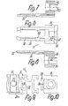
- FIGS. 6 to 10 show a fitting part provided as a crossbar connector 57 for connecting one end of a crossbar profile 13 to a support profile 12 between the ends thereof, the crossbar profile 13 also being indicated in FIG. 9 in the manner of an exploded illustration.
- the crossbar connector 57 has a closely matched to the profile groove 52 of the crossbar profile 13 plug-in sword 58, which goes through in the manner of a T-shaped slide profile over both ends so that it is pushed through the connecting profile 51 over its entire length and at any longitudinal section of the crossbar profile secured against this or with its rear end flush with the truss profile.
- the plug-in sword 58 which can be driven into the connecting profile 51, for example in the manner of a press fit, has a sawtooth shaped toothed longitudinal edges 59 which engage claw-like in the undercut side boundaries of the profile groove 52.
- the plug-in sword On its side belonging to the slot opening of the profile slot 52 and essentially completely filling this slot opening with a profile band, the plug-in sword has receptacles 60 lying on both sides opposite one another in the form of depressions extending into the non-toothed longitudinal edges 59 into which cams of the cross-member profile 13 can interlock positively for additional protection against longitudinal displacements, which are pressed out of the mutually directed C-legs of the connecting profile 51 by deformation, so that no separate fastening elements are required for fastening the crossbar connector 57 to the crossbar profile 13.
- the plug-in sword 57 is attached laterally to an outside of a clamping head 61 formed in one piece with it via its profiled strip 66 in such a way that its rear end is flush with the associated end face 67 of the clamping head 61, which is approximately at right angles.
- This end surface 67 projects into the groove opening of the fitting receptacle profile 31 and the depth of the fitting receptacle 34 engaging web 62, the central plane of which is offset parallel to the sword plane of the plug-in sword 58 and with respect to the plug-in sword 58.
- the clamping head 61 is penetrated by a through hole 63, which also penetrates the engagement web 62 approximately in the middle of its length, the central axis of which lies parallel to the longitudinal direction of the sword.
- a screw 64 which can be seen in FIG. 28, is inserted into the through hole 63, which is expediently formed by a self-tapping countersunk screw, so that the through hole 63 does not have to be provided with a thread beforehand, but instead the screw 64 can be screwed into the through-hole 63 in such a way that it is held in a secured manner on the cross-member connector 57.
- the truss connector 57 connected to the truss profile 13 is inserted with its engagement web 62 into the associated fitting receiving groove 34 of a support profile 12 almost up to abutment on the bottom surface 35, after which the self-tapping screw 64 is expediently screwed into the associated plug groove leg 24 in the region of a locking recess 39.
- the screw 64 can emerge from the inside of the plug groove leg 24 and can freely project into the edge web 29 of the plate.
- the support leg 24a lies directly adjacent to the associated outside of the clamping head 61, which lies transversely to the plug-in sword 58, thus overlaps this clamping head 61 up to the connection to the support profile 12 and at the same time serves to prevent the cross-member profile 13 from tilting relative to the cross-member connector 57 by virtue of the fact that the clamping head 61 engages closely with outer surfaces in an angular receptacle of the cross-member profile 13.
- the furniture unit stands on support feet 68 provided in its corner areas, which practically form components of the front and rear frames or side parts 2 and support the lower ends of the support profiles 12. Corresponding feet can also be provided in reverse at the upper ends for support against a ceiling.
- Each support foot 68 has a base plate 69 for ground support and an adjusting spindle 70 which is rotatably but axially secured to it with its underlying rivet head and which extends approximately over its entire length or almost to the base plate 69 on the one hand with an external thread and on the other hand is provided with wrench flats 71 in the manner of a hexagonal profile, which extends to the base plate 69, so that the thread spiral through the wrench surfaces 71 is flattened polygonally in cross section.
- the adjusting spindle 70 has a further engagement element for a tool, namely, for example, an internal hexagon 72.
- the adjusting spindle 70 is mounted in a threaded foot bearing 73 made of sheet metal and shown in simplified form in FIG. 11, wherein the foot bearing 73 can only be attached by plugging in such a way that the supporting forces are absorbed by limiting the engagement of the plug.
- the foot bearing 73 is approximately U-shaped with a transverse web 74 intended for the stop-limited system at the associated end of the support profile 12, from which a forked long leg 75 and a very short leg 76 projecting across the width of the foot bearing 73 protrude .
- the clear distance between the legs corresponds to the profile width of the support profile in the area of the panel connection profile 22 or the panel thickness of the panels 15 used for the side parts 2.
- a tongue 77 is provided which is slightly offset inwards and also angled from the crosspiece 74 , which is closely adapted to the fitting receiving groove 34 of the support profile 12 and engages in it.
- the foot bearing 73 is secured against lateral movements or precisely aligned laterally, while it is secured positively or without play by the legs 75, 76 against transverse movements to the plate, the legs 75 resting in the manner of spring legs with a slight pretension can.
- a spindle thread 78 is provided in the form of an internal thread, which lies in a collar formed from the crosspiece 74 such that the adjusting spindle 70 engages in the plate connection profile 72 between the grooves 40 in the assembled state.
- the free between the foot bearing 73 and the foot plate 69 Part of the adjusting spindle 70 is accessible over its entire length for the rotary actuation of the adjusting spindle 70 and thus for the height adjustment of the support foot 68.
- shelf supports 79, 81 are provided for intermediate floors 80, which can consist of wood or chipboard, beveled sheet metal plates made of aluminum or the like, and for similar interior accessories for the furniture unit 1 which are to be attached in particular in the area of the locking members 38 in the fitting receiving profiles 31 of the support profiles 12 in such a way that they are also positively secured in the vertical direction.
- the side view of an approximately angular support body 86 having base support 79 is provided on the outside of a support leg 87 approximately as an extension of the other support leg 88 with a pivot bolt 82 which has an elongated locking head 83 in view according to FIG.
- the locking head 89 delimits with its side facing the carrier body 86 a locking groove 84 which is closely matched to the opposing legs of the angled leg 36 and the T-leg 37 of the support profile 12, the thickness of the locking head 83 also being adapted to the clear height of the wider one Area of the fitting receiving groove 34 is adapted.
- a locking pin 85 protrudes from the outside of the locking head 83 facing away from the carrier body 86 and is adapted to the locking recesses 39 of the support profile 12 or the edge profile 14.
- the locking head 83 can be inserted in a pivoting position into the fitting receiving groove 34 until the locking pin 85 engages in a locking recess 39 and can then be secured behind by rotating through 90 °, whereby flat beveled flank zones of the locking bolts formed by the locking head 83 groove 84 lead to a bracing of the carrier leg 87 with respect to the outside of the support profile 12 or the legs 36, 37 of the fitting receiving profile 31.
- the other support leg 88 projects freely from the associated side surface of the support profile 12, its upper side forming a support surface for the easily detachable or removable arrangement of the base 80.
- a securing member 89 in the form of, for example, an upstanding securing pin can be provided, which or the like in a corresponding bore. engages at the bottom of the bottom 80.
- the securing member 89 is expediently surrounded by a groove-shaped depression in the upper side of the carrier body 86, so that possible soiling does not interfere with the support despite the tight adaptation of the securing pin to the hole in the floor.
- the floor support 81 according to FIGS. 22 and 23 differs from the floor support 79 essentially only in that the securing member 89c is provided on the upper side of the support leg 88c with a recess extending approximately over its entire length, into which a corresponding downward protruding member engages can, which, however, also leads to less material.
- Two floor supports 79 and two floor supports 81 are expediently used for each floor 80. Otherwise, the same reference numerals are used in FIGS. 22 and 23 for corresponding parts as in FIGS. 17 to 21, but with the index "c".
- Carrier fittings with swivel bolts 82 or 82c according to FIGS. 17 to 23 can also be provided for other purposes, in each case the swivel bolt allowing a secure and height-adjustable fastening.
- a fitting carrier 90 for attachment to the fitting engagement profile 33 of the respective support profile 12 can be seen from FIGS. 24 to 27, which is simplified in FIG. 24 and shown in greater detail in FIGS. 25 to 27.
- the fitting bracket 90 has an approximately T-shaped bracket engaging member 91 which projects laterally on both sides from a fitting body 96 projecting outward from the fitting engagement profile 33 with end sections and has threaded bores in these end sections for recessed clamping screws 95.
- the almost completely within the fitting engagement profile 33 carrier engagement member 91 forms with its T-crosspiece an engagement head 92 which is relatively closely matched to the inner cross section of the wider area of the fitting engagement groove 43, but is asymmetrical with respect to its central plane.
- One leg of the T-cross bar is provided on the outside with a bevel and on the inside with a stepped surface, of which one step forms a side flank of a side groove 93, which is provided in the T-foot bar and on the freely opposed legs of the fitting engagement profile 33 is adjusted.
- the other step lies in a plane with a corresponding shoulder surface of the other leg of the T-crosspiece, so that this step and the shoulder surface form support surfaces for support on the inside of the mutually directed legs of the fitting engagement profile 33.
- the screws are clamped against the grooved bottom surface 44, so that the bracket 90 is secured in a dimensionally stable manner.
- the fitting carrier 90 has a fork-shaped fitting body 96, between the fork arms of which a hinge body, which is connected, for example, to the plate 18, engages, the hinge body and the fork arms being penetrated in corresponding bores by a hinge pin, and thereby the plate 18 by approximately in the Level of its outside, parallel to the profile support 12 axis is pivotable.
- Fittings for other purposes can be fastened in a corresponding manner to the fitting engagement profiles 33 and 33a of the support profiles 12 and the crossbar profiles 13 with corresponding support engagement members, wherein, for example, 13 hinge fittings with a horizontal hinge axis for hinged front flaps are to be attached to the crossbar profiles.
- the carrier engagement members are each completely spaced in front of or behind the crossbar profiles 13 and the mounting profiles 32 and 32a.
- these support profiles 32 of the support profiles 12 in the rear area of the furniture unit are intended for receiving edge webs of the plate 16, the front flank of these edge webs lying in the plane of the front plate outer surface and only the rear flank opposite the rear plate outer surface is discontinued.
- the horizontal edge webs of the plate 16 engage in a corresponding manner in FIG. 1 in the mounting grooves 41a of the associated truss profiles.
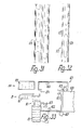
- FIGS. 11 and 24 also show two different cladding profiles 97, 98, of which the cladding profile 97 is intended in particular for attachment to the lower and upper cross-member profile 13 of the front frame in such a way that it passes between the associated support profiles 12.
- This cladding profile 97 has a cladding leg 100, which covers the side surface of the cross-member profile 13 facing the middle of the height of the furniture unit in the region of the mounting profile 32a and the fitting engagement profile 33a up to the connecting flank 53a.
- This cladding leg 100 merges into a diaphragm leg 101 lying at an angle to it, which completely covers the crossbar profile 13 on the front side or on the longitudinal side formed by the fitting engagement profile 33a and is extended beyond the crossbar profile 13.
- the trim leg 100 is of such a thickness that its outer surface lies flush with the associated side surface of the edge profile 14 adjoining it in the region of the fitting receiving profile 31b.
- the cladding profile 97 is structurally combined with at least one sealing lip profile 102, which is attached on the outside in the corner area and projects outward beyond the diaphragm leg 101 in such a way that it can rest against the inside of the plate 17 or 18.
- the fitting bracket 90 can have a cover profile 94 protruding on both sides of the bracket engaging member 91, which can serve for the abutment of the sealing lips 102d in the area of the fitting bracket 90.
- each edge profile 14 or the like with a clip-like detached plastic profile.
- be closed which is expediently designed as a base strip 103 in such a way that it forms a strip-shaped base surface 104 which projects slightly beyond the associated outer surface of the panel and is curved in cross section.
- This standing surface 104 is formed by a crosspiece of the approximately U-shaped standing strip profile, the legs of which engage in the mutually directed profile legs of the fitting receiving profile 31b in such a way that the legs of the standing strip 103 can be supported on the bottom surface of the fitting receiving groove 34b.
- an approximately sheet-metal aperture profile 105 is expediently provided as the base closure, which telescopically engages in the lower end of the support profiles 12 and is also telescopically overlapped on the outside or front by the aperture leg 101 of the trim profile 97 .
- the aperture profile 105 has an approximately vertical aperture leg 106, the upper end of which engages in a slot in the lower end of the respective support profile 12, this slot in the region of the support profiles 32 it is provided that it passes through the central web 42 over a width which corresponds approximately to the slot openings of the mounting slots 41.
- the end edge of the respective support profile 12 is set back in such a way that it ends approximately with the lower edge of the front wall 9 or of the diaphragm arm 101.
- the diaphragm leg 106 which can have an offset for receiving a sealing strip at its upper end, can also be immersed in the mounting groove 41a of the crossbar profile 13 lying above it, which groove faces it.
- the shorter leg of the diaphragm profile 105 is designed as a fastening leg 107 adapted to the foot plate 69 of the support foot 68, which can stand on the floor like a rail with two cranked longitudinal edges and on which the front support feet 68 rest.
- the rear support feet 68 can be placed directly on the floor.
- Corresponding diaphragm profiles 105f can also be provided as a ceiling connection according to FIGS. 29 and 30, the diaphragm limb of which is expediently shorter than in the base area.
- the diaphragm profile 105 can be produced from an approximately mirror-symmetrical U-shaped basic profile 109 according to FIG. 31 by longitudinal division such that a basic profile 109 results in two identical diaphragm profiles 105.
- the base profile 109 is in turn suitable for fastening room divider partitions to the room floor, the ceiling and / or the room side walls in such a way that it encompasses corresponding edge zones of the partition wall in an adjustable manner. This results in significant simplifications in terms of furnishings and room layout.
- the ceiling floor 11e can also be placed on the upper ends of the support profiles 12, so that an upper, separate connection to the ceiling is not required.
- the upper truss profile 13 can lie directly on the underside of the ceiling base 11e, especially since the truss connector or its clamping head 61 - seen in the longitudinal direction of the truss profile 13 and in the installed position - does not protrude above the truss profile 13, but rather lies practically within an imaginary rectangle that consists of the inside of the support leg 24a and the side adjoining it at an angle the connecting profile 51 of the cross-member profile 13 is supplemented.
- the cross-member profile 13 can also be mounted with the support leg 24a at the top, the support leg 24a then expediently being screwed with screws passing through it against the floor 80e lying on it.
- this shelf 80e can be part of an open shelf 110, a display case or the like. be inserted into the furniture unit as a self-contained assembly or insert.
- the truss profile 13 provided for this purpose which expediently lies between an uppermost and a lowermost truss profile, in no way hinders the accessibility of installations in the base area.
- the ceiling floor 11f is indeed placed on the upper ends of the support profiles 12, but it does not extend to the front of the furniture unit as in the embodiment according to FIG. 28, but is like in the case of the design 1, on the other hand, is set back.
- a plate-shaped top panel 111 adjoins the top of the front wall 9f via a transverse joint lying at the height of the ceiling base 11f, which is connected to the front frame in a dimensionally stable manner with upright profiles 112 located on its rear side.
- the lower ends of the upright profiles 112 are fastened with fastening fittings 113 to the upper ends of the support profiles 12, the fastening fittings 113 in at least one of the fastening profiles of each support profile 12, preferably in the Sen support profile 32 and / or engage in its fitting engagement profile 33.
- the stand profiles 112 simultaneously form a telescopic receptacle for the panel profile 105f, which lies behind the top panel 111 provided in the plane of the front wall 9f.
- FIG. 30 shows the support leg 24a of the truss profile can also lie on the top of a ceiling floor and then carries it hanging, whereby the suspended floor 11h is expediently penetrated from below with screws which are secured in the support leg 24a with thread.
- FIG. 30 also shows the use of the cladding profile 97 in the area of the ceiling connection, the cladding profile 97 being arranged vice versa with respect to FIG. 11 with the diaphragm leg 101 pointing upwards.
- a partition divider 114 made of suspended plates 115 or the like can also be used. are attached so that the plates 115 are appropriately spaced behind the rear wall 8.
- vertical support rails 116 with support fittings 117 are advantageously fastened in the fitting engagement profiles 33 of the rear support profiles 12, which can be bent in one piece with them from sheet metal and directly engage in the fitting engagement groove 43 of the fitting engagement profile 33 and, for example, in the Bottom of the fitting engagement groove 43 engaging screws 118 are secured.
- the plates 115 have suspension fittings 119, with which they can be hung on both sides in the mounting rail 116, so that they are secured directly over the furniture unit without a separate floor support.
- the lower and / or the upper connection region of the Partition 114 are covered.
- the joints between adjacent plates 115 are sealed with sealing profiles which are fastened to the mounting rails 116 and bear with sealing lips on the inner sides of the plates 115.
- a heat and / or sound insulation 120 is additionally provided between the rear wall 8 and the plates 115i of the partition wall 114i, which consists, for example, of mineral wool with a thickness of approximately 30 mm.
- the partition wall 114i which consists, for example, of mineral wool with a thickness of approximately 30 mm.
- separate support fittings 117i are provided, which expediently have support engagement members 91i according to FIGS. 25 to 27 and on their outwardly projecting fitting bodies 96i, the respective support rail 116i is fastened with screws.
- the partition 114i can also be fastened with upright profiles 112i, which e.g. are designed so that they can be used in the described manner or instead of the support fitting in the respective support profile.
- a door frame profile 121 is shown, with which a door opening passing through the furniture unit can be limited in such a way that a door leaf can be stored in an advantageous manner, which is then carried exclusively by the skeleton or frame construction of the furniture unit.
- the door frame profile 121 is designed as a groove-like open box profile to the extent that it has no profile chambers that are closed over the circumference.
- Two mutually parallel plug-in channels 122 lie opposite one another in such a way that their bottom surfaces enter through the inner sides of those other opposite profile walls are formed, which are intended for the position parallel to the frame plane.
- the plug-in channels 122 are delimited by inner projections and have a T-shaped profile in the manner of undercut grooves. They are used for the use of corner or miter connectors, which are flat-angled, can be made of sheet metal and are used with their legs for precise alignment in the frame frames that are connected by corners.
- the open side of the door frame profile 121 is in the form of a profile slot 124 between the plug-in channels 122.
- the door frame profile 121 there are further provided at least two screw channels 123 which are at a distance from one another and in particular approximately diagonally opposite one another and which are intended for receiving the helical shanks of self-tapping screws with which the frame frames which are connected by miter are securely secured and braced against one another.
- the screw channels 123 are formed by internal, groove profile-like profile sections, which do not enclose the respective screw shaft over the entire, only over the largest part of its circumference.
- the vertical frame frames or door frame profiles 121 can connect laterally to the outer sides of the plates 15 of the side parts 2 in such a way that they at least partially cover the associated rear support profile 12 with a slightly recessed profile section lying on one side of the profile slot 124.
- the profile section on the other hand, which protrudes further and lies on the other side of the profile slot 124, is flush with the partition wall 114 or with the outside of its plate 115 and forms a joint with the opposite edge thereof, which is the same size as the other joints between the plates 115 the partition 114 is.
- the vertical door frame profiles 121 can be fastened with suitable fittings directly to the support profile 12 or to one of its fastening profiles.
- the door frame profile 121 forms a recessed profile rebate 125 with groove-shaped seal receptacles for door seals, this profile rebate 125 being intended for the engagement of the door leaf 126, which is hinged 127 directly on the associated vertical one, by means of a door frame profile 121
- the frame frame formed is to be stored.
- the door arrangement described represents an embodiment of the invention for furniture units and other room separations.
- the cross-member connectors 57, the floor brackets 79, the fitting brackets 90 and similar fitting parts made of plastic in the case of a very low load design, preferably a metallic design of at least one of these fitting parts is advantageously provided as a die-cast part.
Landscapes
- Engineering & Computer Science (AREA)
- General Engineering & Computer Science (AREA)
- Mechanical Engineering (AREA)
- Life Sciences & Earth Sciences (AREA)
- Wood Science & Technology (AREA)
- Assembled Shelves (AREA)
Applications Claiming Priority (2)
| Application Number | Priority Date | Filing Date | Title |
|---|---|---|---|
| DE19883834276 DE3834276A1 (de) | 1988-10-08 | 1988-10-08 | Moebeleinheit |
| DE3834276 | 1988-10-08 |
Publications (2)
| Publication Number | Publication Date |
|---|---|
| EP0363720A2 true EP0363720A2 (fr) | 1990-04-18 |
| EP0363720A3 EP0363720A3 (fr) | 1991-02-27 |
Family
ID=6364666
Family Applications (1)
| Application Number | Title | Priority Date | Filing Date |
|---|---|---|---|
| EP19890117709 Withdrawn EP0363720A3 (fr) | 1988-10-08 | 1989-09-26 | Corps de meuble |
Country Status (2)
| Country | Link |
|---|---|
| EP (1) | EP0363720A3 (fr) |
| DE (1) | DE3834276A1 (fr) |
Families Citing this family (2)
| Publication number | Priority date | Publication date | Assignee | Title |
|---|---|---|---|---|
| DE102019105795B4 (de) * | 2019-03-07 | 2021-02-25 | Dieter Otto Wiedenroth | Strangförmiges Verbindungselement mit einem primären und einem sekundären Profil |
| DE102021107706A1 (de) | 2021-03-26 | 2022-09-29 | Dieter Otto Wiedenroth | Modulbefestigungssystem sowie ein damit geschaffenes Flächenelement |
Family Cites Families (15)
| Publication number | Priority date | Publication date | Assignee | Title |
|---|---|---|---|---|
| DE1303195B (fr) * | 1971-06-09 | Mengeringhausen M | ||
| DE7324704U (de) * | 1974-03-21 | Greiner A | Aufbauelement für Kastenmöbel | |
| US3150903A (en) * | 1962-10-22 | 1964-09-29 | Vega Ind Inc | Frame structure for cabinets and the like |
| FR2164087A5 (fr) * | 1971-12-08 | 1973-07-27 | Morel Phillippe | |
| DE2904771C2 (de) * | 1979-02-08 | 1982-02-11 | Gebrüder Vieler GmbH, 5860 Iserlohn | Rohrgestell für Podeste, Theken, Regale, Schränke o.dgl. |
| GB2061092B (en) * | 1979-08-08 | 1984-06-06 | Worrallo A C | Panel support structure |
| DE3310225C2 (de) * | 1983-03-22 | 1986-07-03 | Heinz Georg Hünibach Thun Baus | Bauelement |
| DE3153126C2 (en) * | 1981-08-24 | 1987-12-10 | Knuerr-Mechanik Fuer Die Elektronik Ag, 8000 Muenchen, De | Door stop for furniture parts |
| DE3206874C1 (de) * | 1982-02-26 | 1983-07-07 | Selecta-Werk GmbH Bank- u. Kasseneinrichtungen, 5760 Arnsberg | Vorrichtung zur Befestigung von Querstreben oder dergleichen an längsverlaufenden Profilstäben mit Längsnuten und -stegen |
| DE3224711A1 (de) * | 1982-07-02 | 1984-01-05 | Winfried 5000 Köln Scholta | Profilstab zur aufnahme von platten- o. stabfoermigem wandungsmaterial, insbes. z. bau von fruehbeeten etc. |
| DE8405083U1 (de) * | 1984-02-20 | 1984-05-30 | Christian Holzäpfel GmbH, 7240 Horb | Schrank |
| US4650261A (en) * | 1984-07-10 | 1987-03-17 | Russell William, Ltd. | Fastener for coupling panels |
| DE3603393A1 (de) * | 1986-02-05 | 1987-08-06 | Bayer Irene | Verbindungen fuer flexibles montagesystem |
| DE3625046A1 (de) * | 1986-07-24 | 1988-01-28 | Karl Michel | Profilelementesystem zum aufbau von rahmenteilen fuer theken, kabinen, kleiderstaender und dergl. |
| DE3634729A1 (de) * | 1986-10-31 | 1987-05-27 | Manfred Neu | Bauelement zum befestigen von glasscheiben |
-
1988
- 1988-10-08 DE DE19883834276 patent/DE3834276A1/de not_active Withdrawn
-
1989
- 1989-09-26 EP EP19890117709 patent/EP0363720A3/fr not_active Withdrawn
Also Published As
| Publication number | Publication date |
|---|---|
| EP0363720A3 (fr) | 1991-02-27 |
| DE3834276A1 (de) | 1990-04-12 |
Similar Documents
| Publication | Publication Date | Title |
|---|---|---|
| DE69522485T2 (de) | Zusammensetzungen von Pfosten und Riegeln für ein Wandsystem, Unterkonstruktion aus Pfosten hierfür | |
| DE3688977T2 (de) | System von trennwandplatten. | |
| DE10136681A1 (de) | Rahmengestell | |
| DE1484078A1 (de) | Trennwand | |
| DE3438364C1 (de) | Bausatz fuer individuell gestaltbare Moebelgestelle,wie Schauvitrinen,Verkaufstheken,Messemobiliar o.dgl. | |
| EP1870529B1 (fr) | Mur/ensemble de coffre pour une construction de cadre | |
| DE3436492A1 (de) | Verbund-stangenprofil | |
| EP0364768A1 (fr) | Elément de cloison de séparation | |
| DE29508686U1 (de) | Bausatz zum Erstellen von Umkleidekabinen, Trennwänden u.dgl. | |
| DE8900617U1 (de) | Bauelementsatz | |
| DE3712990C2 (fr) | ||
| DE3834276A1 (de) | Moebeleinheit | |
| DE69209472T2 (de) | Verkleidungssystem für Vorhangsfassade | |
| DE69002041T2 (de) | Montagesystem und montageelemente für trennwände in bürogebäuden und dergleichen. | |
| AT400390B (de) | Profilleistensystem | |
| DE19848506B4 (de) | Schrankwand in Systembauweise | |
| AT398271B (de) | Profilleistensystem | |
| DE29714821U1 (de) | Küchenmöbelsystem in wangenbauweise, insbesondere zur un- und/oder bedingten Wandmontage | |
| DE3625046A1 (de) | Profilelementesystem zum aufbau von rahmenteilen fuer theken, kabinen, kleiderstaender und dergl. | |
| DE4016421A1 (de) | Fliegenfenster | |
| EP0713662B1 (fr) | Système de mobilier | |
| DE29920614U1 (de) | Tafelsystem | |
| DE10206258A1 (de) | Gestellsystem | |
| DE19950853C2 (de) | Möbel mit einem tragenden Gestell | |
| DE29719761U1 (de) | Vorrichtung zum lösbaren Verbinden von Wandelementen |
Legal Events
| Date | Code | Title | Description |
|---|---|---|---|
| PUAI | Public reference made under article 153(3) epc to a published international application that has entered the european phase |
Free format text: ORIGINAL CODE: 0009012 |
|
| AK | Designated contracting states |
Kind code of ref document: A2 Designated state(s): AT BE CH DE FR GB IT LI LU NL |
|
| PUAL | Search report despatched |
Free format text: ORIGINAL CODE: 0009013 |
|
| 17P | Request for examination filed |
Effective date: 19901220 |
|
| AK | Designated contracting states |
Kind code of ref document: A3 Designated state(s): AT BE CH DE FR GB IT LI LU NL |
|
| 17Q | First examination report despatched |
Effective date: 19930201 |
|
| STAA | Information on the status of an ep patent application or granted ep patent |
Free format text: STATUS: THE APPLICATION IS DEEMED TO BE WITHDRAWN |
|
| 18D | Application deemed to be withdrawn |
Effective date: 19940817 |