EP0363754A1 - Distributeur automatique pour réservoir de chasse d'eau - Google Patents
Distributeur automatique pour réservoir de chasse d'eau Download PDFInfo
- Publication number
- EP0363754A1 EP0363754A1 EP89118073A EP89118073A EP0363754A1 EP 0363754 A1 EP0363754 A1 EP 0363754A1 EP 89118073 A EP89118073 A EP 89118073A EP 89118073 A EP89118073 A EP 89118073A EP 0363754 A1 EP0363754 A1 EP 0363754A1
- Authority
- EP
- European Patent Office
- Prior art keywords
- container
- machine according
- water box
- water
- toilet
- Prior art date
- Legal status (The legal status is an assumption and is not a legal conclusion. Google has not performed a legal analysis and makes no representation as to the accuracy of the status listed.)
- Granted
Links
- 238000011010 flushing procedure Methods 0.000 title abstract description 4
- XLYOFNOQVPJJNP-UHFFFAOYSA-N water Substances O XLYOFNOQVPJJNP-UHFFFAOYSA-N 0.000 claims abstract description 117
- 239000004480 active ingredient Substances 0.000 claims abstract description 21
- 239000007787 solid Substances 0.000 claims abstract description 6
- 239000000126 substance Substances 0.000 claims description 23
- 239000012141 concentrate Substances 0.000 claims description 18
- 239000013543 active substance Substances 0.000 claims description 11
- 230000009182 swimming Effects 0.000 claims description 5
- 210000003127 knee Anatomy 0.000 claims description 4
- 239000003205 fragrance Substances 0.000 claims description 3
- 230000000630 rising effect Effects 0.000 claims description 2
- 230000003247 decreasing effect Effects 0.000 claims 1
- 239000012459 cleaning agent Substances 0.000 abstract description 3
- 239000003599 detergent Substances 0.000 description 5
- 238000004140 cleaning Methods 0.000 description 3
- 239000004033 plastic Substances 0.000 description 3
- 238000009423 ventilation Methods 0.000 description 3
- 238000013022 venting Methods 0.000 description 3
- 230000007423 decrease Effects 0.000 description 2
- 238000007654 immersion Methods 0.000 description 2
- 239000000463 material Substances 0.000 description 2
- 239000000725 suspension Substances 0.000 description 2
- 206010003830 Automatism Diseases 0.000 description 1
- 229920006328 Styrofoam Polymers 0.000 description 1
- 230000015572 biosynthetic process Effects 0.000 description 1
- 239000007799 cork Substances 0.000 description 1
- 239000000645 desinfectant Substances 0.000 description 1
- 238000012377 drug delivery Methods 0.000 description 1
- 230000000694 effects Effects 0.000 description 1
- 230000005484 gravity Effects 0.000 description 1
- 239000007788 liquid Substances 0.000 description 1
- 238000000034 method Methods 0.000 description 1
- 238000005293 physical law Methods 0.000 description 1
- 239000008261 styrofoam Substances 0.000 description 1
- 230000001960 triggered effect Effects 0.000 description 1
- 238000005406 washing Methods 0.000 description 1
Images


Classifications
-
- E—FIXED CONSTRUCTIONS
- E03—WATER SUPPLY; SEWERAGE
- E03D—WATER-CLOSETS OR URINALS WITH FLUSHING DEVICES; FLUSHING VALVES THEREFOR
- E03D9/00—Sanitary or other accessories for lavatories ; Devices for cleaning or disinfecting the toilet room or the toilet bowl; Devices for eliminating smells
- E03D9/02—Devices adding a disinfecting, deodorising, or cleaning agent to the water while flushing
- E03D9/03—Devices adding a disinfecting, deodorising, or cleaning agent to the water while flushing consisting of a separate container with an outlet through which the agent is introduced into the flushing water, e.g. by suction ; Devices for agents in direct contact with flushing water
- E03D9/033—Devices placed inside or dispensing into the cistern
- E03D9/038—Passive dispensers, i.e. without moving parts
Definitions
- the invention relates to a toilet water box machine with a side opening container for receiving a solid, but soluble in water with the formation of an active ingredient, toilet cleaner substance, the container receiving the toilet cleaner substance in a closed lower part, and wherein the lateral opening of the container is above the maximum area filled by the toilet cleaner substance and is designed both as the outlet of the active ingredient concentrate when the water tank is drained and as the inlet of the pure water that rises again when the water tank is filled.
- DE-OS 28 30 965 describes a plastic container to be used in a toilet water tank for a disinfectant and / or cleaning agent.
- This well-known toilet water machine is made of a plastic with a specific weight of more than one and is intended to Ver need its contents on the bottom of the filled water box.
- the plastic container of this water box machine consists of a lower part that holds the water-soluble cleaning substance and an adjoining upper part that is open at the upper end.
- the known container has a lateral bore immediately above the maximum fill level of the detergent substance.
- the well-known water tank machine When used, the well-known water tank machine can be thrown into the toilet cistern. Due to the low center of gravity, the machine orientates itself with the opening upwards during immersion and slowly runs full of water through the side hole. It sinks to the bottom of the water tank. The water inside the container dissolves the detergent substance so that an active ingredient concentrate forms in the container. This should be dosed into the remaining water flowing to the toilet when the water drains after the water level in the water tank has dropped to a level below the tank height.
- a circulation through the upper opening and the lateral opening of the container can also form in the idle state, that is to say when the water box is not in use, so that the water in the water box is already there is increasingly enriched with active ingredient before rinsing.
- the consumption of cleaning agent is corresponding considerable even when the water tank is not in use.
- the invention has for its object to provide a water box machine from which active ingredient concentrate is only released when the water in the water box has essentially already run out.
- the solution according to the invention for the above-mentioned water box machine with a container holding the toilet cleaner substance in its lower part with a lateral outlet opening for the active ingredient concentrate is that the upper part of the container opposite the lower part receiving the toilet cleaner substance is always for free swimming of the entire device has below the water surface of the filled water tank held output of the side opening designed float and that the side opening is secured against leakage of the active ingredient concentrate when the water box is full.
- the automatic water tank always floats when the water tank is full, but the only lateral opening of the container which is provided as an outlet for the active ingredient concentrate is below the water surface.
- a second container opening required for filling or emptying the container interior, at least for the purpose of venting or venting, is always located above the water surface, so that the water in the water tank cannot circulate through the container.
- this is arranged or designed such that the active ingredient concentrate, which is generally heavier than pure water in general - because of the higher density - cannot escape from the side opening before such active ingredient delivery, is desirable when using the cistern.
- At least one buoyancy body for floating with an approximately vertically standing container is provided as a float on a freely floating water box automat of the present type.
- an air chamber can also be provided as a float within the container for floating with an approximately vertical container;
- the container should have a vent pipe which dips from the top downward but ends above the level of the lateral opening and should also be closed when in use - apart from the vent and the lateral opening.
- Such a container filled with toilet cleaner substance according to the first or second alternative can be placed in the toilet water tank without connection or suspension.
- the swimming depth in the first alternative is determined by the selection of the buoyancy bodies and in the second alternative by the length of the ventilation tube protruding into the interior of the container and the resulting size of the air chamber that forms. Because of this depth, the water is filled via the water itself Lateral container opening intended for drug delivery.
- Such a water box automat of the first or second alternative thus has two openings, namely the side opening and the upper (venting) opening, but the latter can never be immersed in water, so that water penetrates the container through the side opening but because of the lack of possibility a circulation cannot flow out.
- a further improvement of the design of the first or second alternative is achieved if the lateral opening is introduced into a shoulder provided transversely to the vertical longitudinal axis of the container, so that the normal of the lateral opening runs approximately parallel to the longitudinal axis.
- This longitudinal axis parallel water inflow or active substance delivery opening achieves the surprising effect that the active substance concentrate dissolved in the container is kept inside the container when the machine is floating or is even pressed into it. Because of the specific, relatively heavy active ingredient concentrate, this cannot flow out of the opening which is directed upward according to the further embodiment of the invention.
- an essentially cylindrical shape can be provided for the container of the aforementioned water tank machine.
- an increased resistance to the flow of the flowing water and a better active substance flushing are achieved if the container has an essentially conical wall with an increasing diameter from top to bottom.
- the container is to be closed at its lower end with a cover having a conical wall or frame with a diameter that decreases from top to bottom.
- the conical cover frame which tapers downwards, reduces the risk of the water box automatism getting caught in the water box linkage.
- a third alternative of the water box machine according to the invention is that as a float at least one buoyancy container tipping when floating towards the side opening is provided, that on the outside of the side opening a siphon with an upward knee or apex and a downward outlet or inlet is formed and that the siphon has an air chamber on the side of the apex with an air bubble closing the apex when the container floats and tilts.
- a container filled with toilet cleaner substance is also placed in the toilet water tank without connection or suspension.
- a depth is given by the float.
- the water is filled at the specified depth Inside the container via the siphon outlet. Only this water reservoir in the container in turn dissolves the active ingredient in solid form. Since the siphon is closed according to the invention when the machine floats by tilting the container with the aid of an air bubble, a connection between the interior of the container enriched with active substance and the pure water remaining outside is excluded.
- the container regardless of the degree of filling with residual detergent substance, always sinks so deep into the water of the water box that the siphon is always completely below the water level.
- the buoyancy body and its dimensioning is therefore chosen so that the container assumes an inclined position when floating.
- the buoyancy body or bodies are preferably designed or arranged with a view to tilting the container when floating by approximately 45 °. In such an inclined position, immersion of the outlet of the siphon and remaining of an opening on the top of the container above the water level can be guaranteed at the same time.
- an air bubble located in an air chamber adjacent to the siphon migrates into the apex of the siphon. In this embodiment, it is therefore a siphon with a closure by an air bubble and not a conventional siphon with a liquid closure.
- the desired inclination of the floating according to the invention can be achieved by one or more buoyancy bodies on or within the container.
- the buoyancy bodies can consist, for example, of cork, styrofoam or the like.
- a defined inclined position is achieved in a simple manner if a relatively small buoyancy body is provided on the container side above the siphon and a relatively large buoyancy body on the opposite container side.
- the geometry and weight distribution should be selected so that the automatic water tank machine rises.
- the air bubble is then forced out of the siphon knee into an air chamber provided on the side thereof, and the active substance concentrate in the container can flow into the remaining water after the water level has dropped further.
- Raising the container when it is placed on the water tank floor is facilitated and, like the unwanted tilting of the floating container with substantially used, relatively heavy active substance substance, is prevented if the container has a specific weight in its lower part, in particular in the tightly closing lid provided there of more than one.
- this object is also achieved if the height of the container and the distance of the lateral opening from the container bottom are selected so that the active substance concentrate only runs into the last two to three liters of the draining water content.
- the side opening for an active substance outflow is evidently closed as long as the water level around the container has not fallen below a certain level.
- the various dimensions of the water box automat according to the invention possibly also the position of the ventilation pipe, can therefore be easily selected so that the active substance concentrate is only introduced in the last two to three liters of the water box content.
- a further embodiment of the invention consists in designing the side opening of the container in its size and / or arrangement for controlled fragrance delivery.
- This solution is particularly suitable for the alternatives of the water box automat according to the invention, in which no siphon is attached to the side opening. If the normal of the side opening then in certain Is designed in an angular range of 0 to 90 ° with respect to the longitudinal axis of the container, a fragrance release between strong and extremely weak dosage can be predetermined.
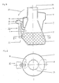
- lateral opening 1 on a container designated overall by 2, which receives a solid but water-soluble toilet cleaner substance 4 in its lower part 3.
- the lateral opening 1 of the container 2 is above the maximum level 5 of the toilet cleaner substance 4.
- the lateral opening 1 serves both as the outlet of the active substance concentrate formed when the detergent substance 4 is dissolved when the water tank (not shown) is drained off and also as the inlet of the when filling up the water tank again rising pure water.
- the bottom part 3 receiving the toilet cleaner substance 4 ge Opposite upper part 6 of the container 2 has a float designed for free swimming of the water tank automat designated as a whole at 7, with the outlet of the lateral opening 1 always held below the water surface 8 of the filled water tank, which is designed as an air chamber 9 in the exemplary embodiment according to FIG. 1.
- a vent pipe 10 projects into the air chamber 9 of the upper part 6 of the container 2 from top to bottom.
- the vent pipe 10 ends above the level 11 of the side opening 1. It is pushed so far into the upper part 6 that at least the upper opening 12 of the vent pipe 10 always protrudes from the surrounding water surface by floating the device.
- the lateral opening 1 is introduced into a shoulder 14 provided transversely to the vertical longitudinal axis 13 of the container 2 such that the normal 15 of the lateral opening 1 runs approximately parallel to the longitudinal axis 13.
- the upper container part is closed except for a bushing 16 with a ventilation pipe 10.
- a cover 17 is therefore expediently provided at the lower end of the lower part 3. This can be to ensure an always upright position - with approximately vertical longitudinal axis 13 - of the container 2 made of a specific, relatively heavy material, so that the container 2 is still upright when the cleaning substance 4 in the we is considerably used up.
- FIG. 3 shows an exemplary embodiment of a water box automatic machine 7 that is modified compared to FIG. 1. However, the same parts are designated as before.
- a water box automat 7 is provided with an essentially cylindrical wall of the container 2, the container 2 according to FIG. 3 - also in its lower part 3a - should be conical with an increasing diameter from top to bottom. This results in increased resistance to the flow of the flowing water when sinking to the bottom of the water tank, and at the same time the active ingredient washing is improved.
- FIG. 3 also shows an embodiment of a conical cover 17a, the diameter of which - also measured perpendicular to the longitudinal axis 13 - decreases from top to bottom.
- a conical container 2 which can be referred to as a conical container 2, if appropriate with reference to a conical container 2, reduces the risk of getting caught with the water box linkage due to its shape.
- FIGS. 4 and 5 Another embodiment of the water box automat according to the invention is described with reference to FIGS. 4 and 5.
- the same or corresponding parts are designated with the same reference numerals as in FIGS. 1 and 2.
- the container 2 according to FIGS. 4 and 5 has two different floats the large buoyancy body 18 and 19.
- a siphon, generally designated 20, with an upwardly directed knee or apex 21 and with a downwardly directed inlet or outlet 22 is formed on the outside of the lateral opening 1 of the container 2.
- the siphon 20 has an air chamber 23 on the side of the apex 21 with an air bubble which is intended to close the apex 21 when the container 2 floats or tilts.
- buoyancy body 18 opposite the siphon 20 is substantially larger than the buoyancy body 19 adjoining the siphon 20.
- the container tilts in the direction of the arrow 24, so that (for example, in a tilt position pivoted by approximately 45 ° with respect to the vertical longitudinal axis 13) it is no longer the air chamber 23 but the apex 21 that contains the highest point of the siphon 20.
- the air bubble originally collected in the air chamber 23 then flows into the area of the apex 21 and closes the siphon 20.
Landscapes
- Public Health (AREA)
- Health & Medical Sciences (AREA)
- Water Supply & Treatment (AREA)
- Life Sciences & Earth Sciences (AREA)
- Engineering & Computer Science (AREA)
- Hydrology & Water Resources (AREA)
- Epidemiology (AREA)
- Bidet-Like Cleaning Device And Other Flush Toilet Accessories (AREA)
- Sanitary Device For Flush Toilet (AREA)
- Detergent Compositions (AREA)
- Slide Fasteners, Snap Fasteners, And Hook Fasteners (AREA)
- Furnace Housings, Linings, Walls, And Ceilings (AREA)
- Soil Working Implements (AREA)
- Permanent Magnet Type Synchronous Machine (AREA)
Priority Applications (1)
| Application Number | Priority Date | Filing Date | Title |
|---|---|---|---|
| AT89118073T ATE82347T1 (de) | 1988-10-08 | 1989-09-29 | Wc-wasserkastenautomat. |
Applications Claiming Priority (2)
| Application Number | Priority Date | Filing Date | Title |
|---|---|---|---|
| DE3834262A DE3834262A1 (de) | 1988-10-08 | 1988-10-08 | Wc-wasserkastenautomat |
| DE3834262 | 1988-10-08 |
Publications (2)
| Publication Number | Publication Date |
|---|---|
| EP0363754A1 true EP0363754A1 (fr) | 1990-04-18 |
| EP0363754B1 EP0363754B1 (fr) | 1992-11-11 |
Family
ID=6364656
Family Applications (2)
| Application Number | Title | Priority Date | Filing Date |
|---|---|---|---|
| EP89118073A Expired - Lifetime EP0363754B1 (fr) | 1988-10-08 | 1989-09-29 | Distributeur automatique pour réservoir de chasse d'eau |
| EP89910860A Pending EP0437461A1 (fr) | 1988-10-08 | 1989-09-29 | Caisse a eau automatique pour w.-c. |
Family Applications After (1)
| Application Number | Title | Priority Date | Filing Date |
|---|---|---|---|
| EP89910860A Pending EP0437461A1 (fr) | 1988-10-08 | 1989-09-29 | Caisse a eau automatique pour w.-c. |
Country Status (13)
| Country | Link |
|---|---|
| US (1) | US5317762A (fr) |
| EP (2) | EP0363754B1 (fr) |
| JP (1) | JPH04501148A (fr) |
| AT (1) | ATE82347T1 (fr) |
| BR (1) | BR8907695A (fr) |
| CA (1) | CA2000279A1 (fr) |
| DE (2) | DE3834262A1 (fr) |
| DK (1) | DK59191A (fr) |
| ES (1) | ES2036323T3 (fr) |
| GR (1) | GR3006360T3 (fr) |
| MX (1) | MX172567B (fr) |
| MY (1) | MY104231A (fr) |
| WO (1) | WO1990004069A1 (fr) |
Cited By (1)
| Publication number | Priority date | Publication date | Assignee | Title |
|---|---|---|---|---|
| WO2008062364A1 (fr) * | 2006-11-21 | 2008-05-29 | Valagam Raghunathan | Distributeur de matière apte à se dissoudre pour des toilettes |
Families Citing this family (5)
| Publication number | Priority date | Publication date | Assignee | Title |
|---|---|---|---|---|
| US6055679A (en) * | 1995-03-03 | 2000-05-02 | S. C. Johnson & Son, Inc. | Passive lavatory cleanser dispensing system |
| USD370710S (en) | 1995-03-03 | 1996-06-11 | S. C. Johnson & Son, Inc. | Dispenser for cleanser compositions |
| US5689837A (en) * | 1996-06-11 | 1997-11-25 | Katona; Thomas J. | Water actuated toilet fan |
| US9580896B2 (en) * | 2014-07-05 | 2017-02-28 | John David Hopkins | Apparatus and method for prolonged active agent in aqueous systems |
| USD1001645S1 (en) | 2022-07-12 | 2023-10-17 | DaVinici II CSJ, LLC | Mermaid bottle |
Citations (4)
| Publication number | Priority date | Publication date | Assignee | Title |
|---|---|---|---|---|
| FR1560302A (fr) * | 1966-11-14 | 1969-03-21 | ||
| DE2830965A1 (de) * | 1978-07-14 | 1980-01-24 | Henkel Kgaa | Kunststoffbehaelter mit desinfektions und/oder reinigungsmittel |
| US4534071A (en) * | 1984-08-06 | 1985-08-13 | Block Drug Company, Inc. | Automatic dispenser for disinfectant and bowl cleaning fluid |
| US4764992A (en) * | 1986-07-18 | 1988-08-23 | The Drackett Company | Dispenser having air lock forming means |
Family Cites Families (8)
| Publication number | Priority date | Publication date | Assignee | Title |
|---|---|---|---|---|
| GB946812A (en) * | 1961-08-09 | 1964-01-15 | Thornton & Ross Ltd | A disinfecting or deodorising device for flushing cisterns |
| US3831205A (en) * | 1972-04-03 | 1974-08-27 | Clorox Co | Automatic dispensing apparatus |
| FI812149A7 (fi) * | 1980-07-14 | 1982-01-15 | Sterling Drug Inc | Hajotuslaite WC-laitteita varten. |
| US4530118A (en) * | 1982-02-08 | 1985-07-23 | The Drackett Company | Passive dispenser |
| US4453278A (en) * | 1983-01-06 | 1984-06-12 | Knomark, Inc. | Chemical dispenser |
| DE3339210A1 (de) * | 1983-10-28 | 1985-05-09 | Werner & Mertz Gmbh, 6500 Mainz | Vorrichtung fuer die zugabe einer vorbestimmten menge eines wirkstoffes in einen wassertank |
| US4534070A (en) * | 1984-08-06 | 1985-08-13 | Block Drug Company, Inc. | Automatic toilet bowl cleaner and depletion signal |
| US4828803A (en) * | 1987-10-05 | 1989-05-09 | Aquality, Inc. | Swimming pool chemical dispenser and method of making same |
-
1988
- 1988-10-08 DE DE3834262A patent/DE3834262A1/de active Granted
-
1989
- 1989-09-29 DE DE8989118073T patent/DE58902691D1/de not_active Expired - Fee Related
- 1989-09-29 ES ES198989118073T patent/ES2036323T3/es not_active Expired - Lifetime
- 1989-09-29 EP EP89118073A patent/EP0363754B1/fr not_active Expired - Lifetime
- 1989-09-29 BR BR898907695A patent/BR8907695A/pt unknown
- 1989-09-29 AT AT89118073T patent/ATE82347T1/de not_active IP Right Cessation
- 1989-09-29 US US07/671,736 patent/US5317762A/en not_active Expired - Fee Related
- 1989-09-29 JP JP1510211A patent/JPH04501148A/ja active Pending
- 1989-09-29 WO PCT/EP1989/001144 patent/WO1990004069A1/fr not_active Ceased
- 1989-09-29 EP EP89910860A patent/EP0437461A1/fr active Pending
- 1989-10-06 CA CA002000279A patent/CA2000279A1/fr not_active Abandoned
- 1989-10-06 MX MX017871A patent/MX172567B/es unknown
- 1989-10-07 MY MYPI89001380A patent/MY104231A/en unknown
-
1991
- 1991-04-03 DK DK059191A patent/DK59191A/da not_active Application Discontinuation
-
1992
- 1992-11-26 GR GR920402718T patent/GR3006360T3/el unknown
Patent Citations (4)
| Publication number | Priority date | Publication date | Assignee | Title |
|---|---|---|---|---|
| FR1560302A (fr) * | 1966-11-14 | 1969-03-21 | ||
| DE2830965A1 (de) * | 1978-07-14 | 1980-01-24 | Henkel Kgaa | Kunststoffbehaelter mit desinfektions und/oder reinigungsmittel |
| US4534071A (en) * | 1984-08-06 | 1985-08-13 | Block Drug Company, Inc. | Automatic dispenser for disinfectant and bowl cleaning fluid |
| US4764992A (en) * | 1986-07-18 | 1988-08-23 | The Drackett Company | Dispenser having air lock forming means |
Cited By (1)
| Publication number | Priority date | Publication date | Assignee | Title |
|---|---|---|---|---|
| WO2008062364A1 (fr) * | 2006-11-21 | 2008-05-29 | Valagam Raghunathan | Distributeur de matière apte à se dissoudre pour des toilettes |
Also Published As
| Publication number | Publication date |
|---|---|
| DK59191D0 (da) | 1991-04-03 |
| ATE82347T1 (de) | 1992-11-15 |
| DK59191A (da) | 1991-04-03 |
| MX172567B (es) | 1994-01-03 |
| DE3834262A1 (de) | 1990-04-19 |
| CA2000279A1 (fr) | 1990-04-08 |
| BR8907695A (pt) | 1991-08-20 |
| EP0437461A1 (fr) | 1991-07-24 |
| JPH04501148A (ja) | 1992-02-27 |
| WO1990004069A1 (fr) | 1990-04-19 |
| EP0363754B1 (fr) | 1992-11-11 |
| GR3006360T3 (fr) | 1993-06-21 |
| DE58902691D1 (de) | 1992-12-17 |
| DE3834262C2 (fr) | 1993-04-29 |
| MY104231A (en) | 1994-02-28 |
| US5317762A (en) | 1994-06-07 |
| ES2036323T3 (es) | 1993-05-16 |
Similar Documents
| Publication | Publication Date | Title |
|---|---|---|
| EP0039309B1 (fr) | Dispositif de dosage d'un additif | |
| DE69704285T2 (de) | Selbstsaugender siphon, insbesondere fur bewasserung | |
| CH663045A5 (de) | Ablaufgarnitur fuer einen spuelkasten. | |
| EP0219622A2 (fr) | Dispositif pour contrôler au moins un courant de gaz | |
| DE1784944C3 (de) | Schwimmer für Klosettspülkästen | |
| DE2458192B2 (de) | Spülkasten für ein Wasserklosett | |
| EP0363754B1 (fr) | Distributeur automatique pour réservoir de chasse d'eau | |
| DE60126606T2 (de) | Versorgungsflüssigkeitsspender für toilettenbecken | |
| DE19631078A1 (de) | Verfahren zur Reinigung von Toilettenbecken | |
| DE3244458A1 (de) | Passiver dosierspender mit doppeltem lueftungssystem | |
| DE60206617T2 (de) | Abwärtshub-spender | |
| DE19901457B4 (de) | Vorrichtung zur Abgabe von Wirkstoffen in das Spülwasser eines Toilettenbeckens oder dergleichen | |
| DE10246866A1 (de) | Speicherbehälter, insbesondere Toilettenspülkasten | |
| DE69104355T2 (de) | Dosiervorrichtung für einen Toiletten-Wasserkasten. | |
| DE2916247C2 (de) | Behälter für ein Reinigungsmittel zum Reinigen eines Klosettspülkastens und einer Klosettschlüssel | |
| WO1980000984A1 (fr) | Appareil de chasse d'eau pour cuvette de wc | |
| DE4137768C1 (en) | Automatic hoist with downwards open bell - has outlet tube, whose top end retains movably top-open float pot | |
| DE2624163B2 (de) | Verfahren zum Desinfizieren und Reinigen einer sanitären Anlage und Vorrichtung zur Durchführung des Verfahrens | |
| WO1992007148A1 (fr) | Doseur automatique basculant pour toilettes | |
| DE602004001402T2 (de) | Flüssigkeitsaktive stoff-abgabevorrichtung für toilettenbecken | |
| DE900199C (de) | Verfahren zur Desinfizierung von Spuelaborten, Pissoiranlagen und aehnlichen sanitaeren Einrichtungen sowie Fluessigkeitszusetzapparat zur Ausfuehrung des Verfahrens | |
| DE7910584U1 (de) | Selbsttaetige dosiervorrichtung fuer wirksubstanzen | |
| DE69005027T2 (de) | Entkeimer. | |
| DE525373C (de) | Durchflusssperre fuer Leichtfluessigkeitsabscheider | |
| DE4312007A1 (de) | Leichtflüssigkeitsabscheider mit Ablaufsperre für die Verbindung vom Leichtflüssigkeitsausgleichsraum zum Schwerflüssigkeitsablauf |
Legal Events
| Date | Code | Title | Description |
|---|---|---|---|
| PUAI | Public reference made under article 153(3) epc to a published international application that has entered the european phase |
Free format text: ORIGINAL CODE: 0009012 |
|
| AK | Designated contracting states |
Kind code of ref document: A1 Designated state(s): ES GR |
|
| 17P | Request for examination filed |
Effective date: 19900518 |
|
| 17Q | First examination report despatched |
Effective date: 19900720 |
|
| XX | Miscellaneous (additional remarks) |
Free format text: VERBUNDEN MIT 89910860.9/0437461 (EUROPAEISCHE ANMELDENUMMER/VEROEFFENTLICHUNGSNUMMER) DURCH ENTSCHEIDUNG VOM 21.10.91. |
|
| GRAA | (expected) grant |
Free format text: ORIGINAL CODE: 0009210 |
|
| AK | Designated contracting states |
Kind code of ref document: B1 Designated state(s): AT BE CH DE ES FR GB GR IT LI LU NL SE |
|
| REF | Corresponds to: |
Ref document number: 82347 Country of ref document: AT Date of ref document: 19921115 Kind code of ref document: T |
|
| XX | Miscellaneous (additional remarks) |
Free format text: VERBUNDEN MIT 89910860.9/0437461 (EUROPAEISCHE ANMELDENUMMER/VEROEFFENTLICHUNGSNUMMER) DURCH ENTSCHEIDUNG VOM 21.10.91. |
|
| GBT | Gb: translation of ep patent filed (gb section 77(6)(a)/1977) | ||
| REF | Corresponds to: |
Ref document number: 58902691 Country of ref document: DE Date of ref document: 19921217 |
|
| ITF | It: translation for a ep patent filed | ||
| ET | Fr: translation filed | ||
| REG | Reference to a national code |
Ref country code: GR Ref legal event code: FG4A Free format text: 3006360 |
|
| REG | Reference to a national code |
Ref country code: ES Ref legal event code: FG2A Ref document number: 2036323 Country of ref document: ES Kind code of ref document: T3 |
|
| PGFP | Annual fee paid to national office [announced via postgrant information from national office to epo] |
Ref country code: CH Payment date: 19930823 Year of fee payment: 5 |
|
| PLBE | No opposition filed within time limit |
Free format text: ORIGINAL CODE: 0009261 |
|
| STAA | Information on the status of an ep patent application or granted ep patent |
Free format text: STATUS: NO OPPOSITION FILED WITHIN TIME LIMIT |
|
| PGFP | Annual fee paid to national office [announced via postgrant information from national office to epo] |
Ref country code: GR Payment date: 19930929 Year of fee payment: 5 |
|
| PGFP | Annual fee paid to national office [announced via postgrant information from national office to epo] |
Ref country code: NL Payment date: 19930930 Year of fee payment: 5 Ref country code: LU Payment date: 19930930 Year of fee payment: 5 |
|
| 26N | No opposition filed | ||
| EPTA | Lu: last paid annual fee | ||
| PG25 | Lapsed in a contracting state [announced via postgrant information from national office to epo] |
Ref country code: LU Free format text: LAPSE BECAUSE OF NON-PAYMENT OF DUE FEES Effective date: 19940929 |
|
| PG25 | Lapsed in a contracting state [announced via postgrant information from national office to epo] |
Ref country code: LI Effective date: 19940930 Ref country code: CH Effective date: 19940930 |
|
| EAL | Se: european patent in force in sweden |
Ref document number: 89118073.9 |
|
| PG25 | Lapsed in a contracting state [announced via postgrant information from national office to epo] |
Ref country code: GR Free format text: THE PATENT HAS BEEN ANNULLED BY A DECISION OF A NATIONAL AUTHORITY Effective date: 19950331 |
|
| PG25 | Lapsed in a contracting state [announced via postgrant information from national office to epo] |
Ref country code: NL Effective date: 19950401 |
|
| NLV4 | Nl: lapsed or anulled due to non-payment of the annual fee | ||
| REG | Reference to a national code |
Ref country code: CH Ref legal event code: PL Ref country code: GR Ref legal event code: MM2A Free format text: 3006360 |
|
| PGFP | Annual fee paid to national office [announced via postgrant information from national office to epo] |
Ref country code: SE Payment date: 20010906 Year of fee payment: 13 |
|
| PGFP | Annual fee paid to national office [announced via postgrant information from national office to epo] |
Ref country code: FR Payment date: 20010911 Year of fee payment: 13 |
|
| PGFP | Annual fee paid to national office [announced via postgrant information from national office to epo] |
Ref country code: AT Payment date: 20010912 Year of fee payment: 13 |
|
| PGFP | Annual fee paid to national office [announced via postgrant information from national office to epo] |
Ref country code: ES Payment date: 20010920 Year of fee payment: 13 |
|
| PGFP | Annual fee paid to national office [announced via postgrant information from national office to epo] |
Ref country code: GB Payment date: 20011003 Year of fee payment: 13 |
|
| PGFP | Annual fee paid to national office [announced via postgrant information from national office to epo] |
Ref country code: DE Payment date: 20011015 Year of fee payment: 13 |
|
| PGFP | Annual fee paid to national office [announced via postgrant information from national office to epo] |
Ref country code: BE Payment date: 20011116 Year of fee payment: 13 |
|
| REG | Reference to a national code |
Ref country code: GB Ref legal event code: IF02 |
|
| PG25 | Lapsed in a contracting state [announced via postgrant information from national office to epo] |
Ref country code: GB Free format text: LAPSE BECAUSE OF NON-PAYMENT OF DUE FEES Effective date: 20020929 Ref country code: AT Free format text: LAPSE BECAUSE OF NON-PAYMENT OF DUE FEES Effective date: 20020929 |
|
| PG25 | Lapsed in a contracting state [announced via postgrant information from national office to epo] |
Ref country code: SE Free format text: LAPSE BECAUSE OF NON-PAYMENT OF DUE FEES Effective date: 20020930 Ref country code: ES Free format text: LAPSE BECAUSE OF NON-PAYMENT OF DUE FEES Effective date: 20020930 Ref country code: BE Free format text: LAPSE BECAUSE OF NON-PAYMENT OF DUE FEES Effective date: 20020930 |
|
| BERE | Be: lapsed |
Owner name: *HENKEL K.G.A.A. Effective date: 20020930 |
|
| PG25 | Lapsed in a contracting state [announced via postgrant information from national office to epo] |
Ref country code: DE Free format text: LAPSE BECAUSE OF NON-PAYMENT OF DUE FEES Effective date: 20030401 |
|
| EUG | Se: european patent has lapsed | ||
| GBPC | Gb: european patent ceased through non-payment of renewal fee |
Effective date: 20020929 |
|
| PG25 | Lapsed in a contracting state [announced via postgrant information from national office to epo] |
Ref country code: FR Free format text: LAPSE BECAUSE OF NON-PAYMENT OF DUE FEES Effective date: 20030603 |
|
| REG | Reference to a national code |
Ref country code: FR Ref legal event code: ST |
|
| REG | Reference to a national code |
Ref country code: ES Ref legal event code: FD2A Effective date: 20031011 |
|
| PG25 | Lapsed in a contracting state [announced via postgrant information from national office to epo] |
Ref country code: IT Free format text: LAPSE BECAUSE OF NON-PAYMENT OF DUE FEES Effective date: 20050929 |