EP0363846A2 - Rear wheel-steering angle control-system for vehicle - Google Patents
Rear wheel-steering angle control-system for vehicle Download PDFInfo
- Publication number
- EP0363846A2 EP0363846A2 EP89118627A EP89118627A EP0363846A2 EP 0363846 A2 EP0363846 A2 EP 0363846A2 EP 89118627 A EP89118627 A EP 89118627A EP 89118627 A EP89118627 A EP 89118627A EP 0363846 A2 EP0363846 A2 EP 0363846A2
- Authority
- EP
- European Patent Office
- Prior art keywords
- angle
- vehicle
- steered
- wheel
- steering angle
- Prior art date
- Legal status (The legal status is an assumption and is not a legal conclusion. Google has not performed a legal analysis and makes no representation as to the accuracy of the status listed.)
- Granted
Links
- 230000005484 gravity Effects 0.000 claims abstract description 19
- 230000001133 acceleration Effects 0.000 claims abstract description 10
- 230000006870 function Effects 0.000 description 5
- 230000004043 responsiveness Effects 0.000 description 3
- 238000010586 diagram Methods 0.000 description 2
- 239000000725 suspension Substances 0.000 description 2
- 238000004519 manufacturing process Methods 0.000 description 1
- 230000009466 transformation Effects 0.000 description 1
Images


Classifications
-
- B—PERFORMING OPERATIONS; TRANSPORTING
- B62—LAND VEHICLES FOR TRAVELLING OTHERWISE THAN ON RAILS
- B62D—MOTOR VEHICLES; TRAILERS
- B62D7/00—Steering linkage; Stub axles or their mountings
- B62D7/06—Steering linkage; Stub axles or their mountings for individually-pivoted wheels, e.g. on king-pins
- B62D7/14—Steering linkage; Stub axles or their mountings for individually-pivoted wheels, e.g. on king-pins the pivotal axes being situated in more than one plane transverse to the longitudinal centre line of the vehicle, e.g. all-wheel steering
- B62D7/15—Steering linkage; Stub axles or their mountings for individually-pivoted wheels, e.g. on king-pins the pivotal axes being situated in more than one plane transverse to the longitudinal centre line of the vehicle, e.g. all-wheel steering characterised by means varying the ratio between the steering angles of the steered wheels
- B62D7/159—Steering linkage; Stub axles or their mountings for individually-pivoted wheels, e.g. on king-pins the pivotal axes being situated in more than one plane transverse to the longitudinal centre line of the vehicle, e.g. all-wheel steering characterised by means varying the ratio between the steering angles of the steered wheels characterised by computing methods or stabilisation processes or systems, e.g. responding to yaw rate, lateral wind, load, road condition
Definitions
- the present invention relates generally to a system for controlling the steering angle of the rear wheels of a vehicle. More particularly, the invention relates to a system for controlling the steering angle of the rear wheels based on a steering operation by a driver.
- Japanese Utility Model First Publication (jikkaisho) No. 62-23773 discloses a system which controls rear wheel steering angle based on vehicle speed.
- the ratio of the front wheel steering angle ⁇ f to the rear wheel steering angle ⁇ r is a constant. This results in improved traveling stability when the vehicle turns a steady circle.
- the responsiveness of the vehicle to emergency handling for better vehicle handling while slaloming is not so good.
- an apparatus for controlling the rear wheel steering angle for a vehicle which comprises a first sensing means for sensing a steered angle, steered angular velocity, and steered angular acceleration of the steering wheel of the vehicle and to provide signals indicative thereof, a second sensing means for sensing vehicle speed to provide a signal indicative thereof, a third means for determining a target steering angle for a rear wheel so as to vary the position where the side slip angle of the vehicle becomes zero with respect to the vehicle's center of gravity based on the signals from the first sensing means and the second sensing means to improve the manoeverability of the vehicle in cornering, and a fourth means for controlling the actual steering angle for the rear wheels according to the target steering angle to achieve stable cornering.
- ⁇ ′ T1(T - T2)
- T1 C1V(aMl3 - 1) / C2 ⁇ bMV2 + C1l (l3 + a) ⁇
- T2 V(bMl3 + I) / bMV2 + C2l(l3 + a)
- M vehicle weight I : yaw moment of inertia l : wheel base l3 : distance between the center of gravity and a position where the lateral slip angle becomes
- the third means determines the target steering angle by setting the position where the side slip angle becomes zero equal to a predetermined fixed position.
- the distance l3 is defined so that the position where the side slip angle of the vehicle becomes zero is in the vicinity of the rear wheel when the magnitude of the steered angle and the steered angular velocity of the steering wheel is small, and the position is near the front wheel when the magnitude of the steered angle and the steered angular velocity of the steering wheel is great, and so that said position is further adjusted according to variations in the turning circle when the steered angular acceleration of the steering wheel is great.
- the signs K, ⁇ , S, and ⁇ ′ are equal to the signs indicated above.
- a system for controlling a steering angle for the rear wheels of a vehicle according to the instant invention is shown.
- Front wheels 1L (left) and 1R (right) are rotatably connected to a steering wheel 3 via a steering gear 4.
- the rotation of the steering wheel 4 by an angle ⁇ causes the front wheels to rotate by an angle ⁇ f .
- a steering gear ratio is a N
- Rear wheels 2L and 2R are suspended by a rear suspension member 7 of a rear suspension system including transverse links 5L and 5R and upper arms 6L and 6R.
- An actuator 9 is provided which is connected between rear knuckle arms 8L and 8R through side rods 10L and 10R to steer the rear wheels 2L and 2R.
- the actuator 9 is a spring centered double acting hydraulic pressure cylinder, which has two chambers each connecting to an electromagnetic proportional pressure control valve 12 through pressure lines 11L and 11R.
- the control valve 12 is connected to a pressure source including a hydraulic pump 13 and a reservoir tank 14 through a pressure line 15 and a drain line 16.
- This control valve 12 is a spring centered three position valve which is adapted for providing no pressure in the pressure line 11L and 11R when both solenoids 12L and 12R are in the OFF state and applying a working pressure to the pressure line 11R which is proportional to a period of time during the solenoid 12R is energized.
- a controller 17 is provided which electronically controls the switching operation and the energized time of the solenoids 12L and 12R.
- This controller 17, as shown in Fig. 2 generally comprises an arithmetic circuit 17a, a digital input signal detecting circuit 17b, a memory circuit 17c, a D/A converter 17d, and a drive circuit 17e.
- a steering angle sensor 18 and a vehicle speed sensor 19 are further provided.
- the steering angle sensor is adapted for sensing the steered angle ⁇ of the steering wheel 3 to provide a digital signal to the digital input detecting circuit 17b.
- the vehicle speed sensor 19 is adapted for sensing vehicle speed V to provide a digital signal to the circuit 17b.
- Signals input from the sensors 18 and 19 cause the arithmetic circuit 17a to determine the ⁇ and the V and to calculate the angular steering velocity ⁇ of the steering wheel and the angular steering acceleration thereof. Subsequently, based on the values of the ⁇ , the ⁇ , the , and the V, values K, a ⁇ , a ⁇ ′ which are previously calculated mathematically using equations as will be described hereinafter are retrieved from the memory circuit 17c. A control signal indicative of steering angle, mathematically calculated in a manner to be described hereinafter, is output to the solenoid of the pressure control valve 12 through the D/A converter 17d and the drive circuit 17e to control the working pressure for steering the rear wheels.
- the controller 17 selectively determines as to whether a current i has to be supplied to the solenoids 12L or 12R of the control valve 12 based on the steered angle ⁇ to provide a working pressure which corresponds to the current i (e.i., a calculated rear wheel steering angle ⁇ r ) to the corresponding pressure lines 11L and 11R.
- This causes actuator 9 to be operated so as to allow the side rods 10L and 10R to be moved by a stroke corresponding to the pressure, steering the rear wheels by an angle corresponding to the mathematically calculated result.
- a rear wheel steering control function for steering the rear wheels is determined so that the side travel speed v3 at a position away from the center of gravity by the distance l3 becomes zero.
- a controller 100 determines the rear wheel target steering angle ⁇ r mathematically using the above formula to control a hydraulic system 200 to actually steer the rear wheels by the angle ⁇ r .
- This control system is disclosed in a commonly owned copending application filed on November 30, 1988, patent application Serial No. 277,745, by Kazunori MORI et al, entitled REAR WHEEL STEER ANGLE CONTROL SYSTEM FOR VEHICLE. The contents of said disclosure being hereby incorporated by reference.
- the hydraulic system 200 for steering the rear wheels provides a first order lag time constant T.
- the actual rear steered angle ⁇ r does not exactly correspond to the mathematically calculated angle ⁇ r . That is, the relation between the actural steered angle and the front wheel steered angle is given by the following equation. It will thus be appreciated that the desired control can not be affected.
- control function G(S) is a fractional expression of a linear expression / a linear expression with respect to the Laplace's operator S.
- the control system requires a digital filter and a high speed arithmetic unit. As a result, the cost of the system is increased.
- the controller 17, according to the invention is adapted for mathematically calculating the rear wheel steering angle ⁇ r so as to cancel the above value 1 / 1 + T ⁇ S.
- the control function G(S) is multiplied by (1 + T ⁇ S) and the resultant rear wheel steering angle ⁇ r , as shown in Fig. 5, is determined so as to satisfy the following equation.
- each the ⁇ T1 + K(T - T2) ⁇ and the T1 (T-T2)S2 are a control constant and thus if these values are replaced by a ⁇ and a ⁇ ′, the following equation obtains.
- the controller 17 can determine the rear wheel steering angle ⁇ r according to the above equation to control the rear wheel steering hydraulic system 300 (this includes parts indicated by numerals 9 through 16 in Fig. 1).
- the distance l3 which is, as mentioned previously, defined between the center of gravity of the vehicle and the position where the side slip angle becomes zero is varied based on the steered angle of the steering wheel ⁇ , the angular velocity of the steering wheel ⁇ , and the angular acceleration of the steering wheel to determine the desired rear wheel steering angle ⁇ r .
- the distance l3 is determined according to data acquired by experimentation based on the specific vehicles or types thereof. For example, while a vehicle is running on a road having continuous gentle curves, the values of the ⁇ and the ⁇ become small.
- the relatively long distance l3 is provided and the rear wheel steering angle can be determined so that the position where the side slip becomes zero is defined relatively near the rear wheels to improve the cornering stability.
- the values of the ⁇ and the ⁇ become relatively great.
- the distance l3 is provided so that the position where the side slip becomes zero is defined relatively near the front wheels and the rear wheel steering angle is determined to improve the cornering stability.
- the distance l3 is determined according the variation of the turning circle to obtain a rear wheel steering angle so as to improve the cornering stability. It will be appreciated that the determination of the rear wheel steering angle based on the values of the ⁇ , the ⁇ , or the can provide highly stable cornering.
- control system is adapted for determining the distance between the center of gravity and the position where side slip becomes zero based on the steered angle of a steering wheel, the angular velocity of steering thereof, or angular acceleration of steering thereof to control rear wheel steering angle. Therefore, the degree of freedom necessary for tuning a control constant for a rear wheel steering angle in order to improve the cornering properties of the vehicle increases and the responsiveness of the vehicle is improved relative to emergency handling to avoid danger and handling when the vehicle is slaloming. Additionally, high responsiveness can be obtained when the vehicle is running on a road in which the turning circle varies frequently.
Landscapes
- Engineering & Computer Science (AREA)
- Physics & Mathematics (AREA)
- Mathematical Physics (AREA)
- Theoretical Computer Science (AREA)
- Chemical & Material Sciences (AREA)
- Combustion & Propulsion (AREA)
- Transportation (AREA)
- Mechanical Engineering (AREA)
- Steering Control In Accordance With Driving Conditions (AREA)
- Steering-Linkage Mechanisms And Four-Wheel Steering (AREA)
Abstract
Description
- The present invention relates generally to a system for controlling the steering angle of the rear wheels of a vehicle. More particularly, the invention relates to a system for controlling the steering angle of the rear wheels based on a steering operation by a driver.
- A system adapted for controlling the steering of the rear wheels of a vehicle is well known in the art. For example, Japanese Utility Model First Publication (jikkaisho) No. 62-23773 discloses a system which controls rear wheel steering angle based on vehicle speed. In this system, when the vehicle is running at a constant speed, the ratio of the front wheel steering angle δf to the rear wheel steering angle δr is a constant. This results in improved traveling stability when the vehicle turns a steady circle. There is however a problem in that the responsiveness of the vehicle to emergency handling for better vehicle handling while slaloming is not so good.
- It is accordingly an object of the present invention to provide an apparatus for controlling the rear wheel steering angle to obtain driving stability regardless of variations in the turning circle or the magnitude of the turning circles which the vehicle encounters.
- According to one aspect of the present invention, there is provided an apparatus for controlling the rear wheel steering angle for a vehicle which comprises a first sensing means for sensing a steered angle, steered angular velocity, and steered angular acceleration of the steering wheel of the vehicle and to provide signals indicative thereof, a second sensing means for sensing vehicle speed to provide a signal indicative thereof, a third means for determining a target steering angle for a rear wheel so as to vary the position where the side slip angle of the vehicle becomes zero with respect to the vehicle's center of gravity based on the signals from the first sensing means and the second sensing means to improve the manoeverability of the vehicle in cornering, and a fourth means for controlling the actual steering angle for the rear wheels according to the target steering angle to achieve stable cornering.
- In the preferred mode, the third means determines the target steering angle δr so as to satisfy the following relation with respect to a steered angle δf of the front wheel,
δr / δf = K + τ · S + τ′ · S²
where
S : a Laplace's operator
K = C₁ {aMV² + C₂ℓ(ℓ₃ - b)} / C₂ {bMV² + C₁ℓ(ℓ₃ - a)}
τ = T1 + K(T - T2)
τ′ = T1(T - T2)
T1 = C₁V(aMℓ₃ - 1) / C₂{bMV² + C₁ℓ (ℓ₃ + a)}
T2 = V(bMℓ₃ + I) / bMV² + C₂ℓ(ℓ₃ + a)
M : vehicle weight
I : yaw moment of inertia
ℓ : wheel base
ℓ₃ : distance between the center of gravity and a position where the lateral slip angle becomes zero
a : distance between the center of gravity and the center point between the front wheels
b : distance between the center of gravity and the center point between the rear wheels
C₁ : cornering power of the two front wheels
C₂ : cornering power of the two rear wheels
V : vehicle speed
T : first order lag time constant - The third means determines the target steering angle by setting the position where the side slip angle becomes zero equal to a predetermined fixed position.
- The distance ℓ₃ is defined so that the position where the side slip angle of the vehicle becomes zero is in the vicinity of the rear wheel when the magnitude of the steered angle and the steered angular velocity of the steering wheel is small, and the position is near the front wheel when the magnitude of the steered angle and the steered angular velocity of the steering wheel is great, and so that said position is further adjusted according to variations in the turning circle when the steered angular acceleration of the steering wheel is great.
- According to another aspect of the invention, there is provided an apparatus for controlling rear wheel steering angle for a vehicle which comprises a first sensing means for sensing a steered angle of a front wheel of the vehicle to provide signals indicative thereof, a second sensing means for sensing vehicle speed to provide a signal indicative thereof, a third means for determining a target steering angle for a rear wheel δr with respect to said steered angle of the front wheel δf according to the relation of δr = (K + τ · S + τ′ · S²)δf based on the signals from said first sensing means and said second sensing means, and a fourth means for controlling an actual steering angle for the rear wheel according to said target steering angle δr to achieve stable cornering. The signs K, τ, S, and τ′ are equal to the signs indicated above.
-
- Fig. 1 is a schematic view which shows a system for controlling a rear wheel steering angle of a vehicle according to the present invention.
- Fig. 2 is a block diagram which shows a rear wheel steering angle control system according to the invention.
- Fig. 3 which shows a two-wheeled vehicle, is an explanatory view for deriving an equation of motion.
- Figs. 4 through 7 are block diagrams which show the relation between a controller for controlling a rear wheel steering angle and a hydraulic system for steering the rear wheels.
- Referring now to the drawings, particularly to Fig. 1, a system for controlling a steering angle for the rear wheels of a vehicle according to the instant invention is shown.
- Front wheels 1L (left) and 1R (right) are rotatably connected to a
steering wheel 3 via asteering gear 4. The rotation of thesteering wheel 4 by an angle ϑ causes the front wheels to rotate by an angle δf. If a steering gear ratio is a N, the relation between the ϑ and the δf is expressed by δf = ϑ/N. Rear wheels rear suspension member 7 of a rear suspension system includingtransverse links upper arms actuator 9 is provided which is connected betweenrear knuckle arms rear wheels - The
actuator 9 is a spring centered double acting hydraulic pressure cylinder, which has two chambers each connecting to an electromagnetic proportionalpressure control valve 12 through pressure lines 11L and 11R. Thecontrol valve 12 is connected to a pressure source including ahydraulic pump 13 and areservoir tank 14 through apressure line 15 and adrain line 16. Thiscontrol valve 12 is a spring centered three position valve which is adapted for providing no pressure in the pressure line 11L and 11R when bothsolenoids solenoid 12R is energized. - A
controller 17 is provided which electronically controls the switching operation and the energized time of thesolenoids controller 17, as shown in Fig. 2, generally comprises an arithmetic circuit 17a, a digital inputsignal detecting circuit 17b, amemory circuit 17c, a D/A converter 17d, and adrive circuit 17e. Asteering angle sensor 18 and avehicle speed sensor 19 are further provided. The steering angle sensor is adapted for sensing the steered angle ϑ of thesteering wheel 3 to provide a digital signal to the digitalinput detecting circuit 17b. Thevehicle speed sensor 19 is adapted for sensing vehicle speed V to provide a digital signal to thecircuit 17b. Signals input from thesensors thereof. Subsequently, based on the values of the ϑ, the ϑ̇, the , and the V, values K, a τ, a τ′ which are previously calculated mathematically using equations as will be described hereinafter are retrieved from the
memory circuit 17c. A control signal indicative of steering angle, mathematically calculated in a manner to be described hereinafter, is output to the solenoid of thepressure control valve 12 through the D/A converter 17d and thedrive circuit 17e to control the working pressure for steering the rear wheels. - The
controller 17 selectively determines as to whether a current i has to be supplied to thesolenoids control valve 12 based on the steered angle ϑ to provide a working pressure which corresponds to the current i (e.i., a calculated rear wheel steering angle δr) to the corresponding pressure lines 11L and 11R. This causesactuator 9 to be operated so as to allow the side rods 10L and 10R to be moved by a stroke corresponding to the pressure, steering the rear wheels by an angle corresponding to the mathematically calculated result. - Referring to Fig. 3, a model of a linear two degrees of freedom for obtaining an equation of motion to determine a target rear wheel steering angle is shown. If the equation of motion is transformed according to Laplace transformation, it is expressed as follows:
M(Sv + Vω) = F₁ + F₂ (1)
ISω = aF₁ - bF₂ (2)
F₁ = C₁β₁ (3)
F₂ = C₂β₂ (4)
where
S : a Laplace's operator
M : a vehicle weight
I : a yawing moment of inertia
ℓ : a wheel base
a : a distance between the center of gravity and the center point between the front wheels
b : a distance between the center of gravity and the center point between the rear wheels
C₁ : cornering power of the two front wheels
C₂ : cornering power of the two rear wheels
β₁ : a side slip angle of a front wheel
β₂ : a side slip angle of a rear wheel
V : vehicle speed
v : vehicle side speed
ω : yaw rate
- If side travel speed at a point away from the center of gravity by a distance ℓ₃ is represented as a v₃, it is given as follows:
v₃ = v - ℓ₃ω (7) - A rear wheel steering control function for steering the rear wheels is determined so that the side travel speed v₃ at a position away from the center of gravity by the distance ℓ₃ becomes zero.
- From v₃ = 0,
v = ℓ₃ω (8) - By substituting the equation (8) for the equations (1) through (6), the following equations are obtained.
Mℓ₃Sω + MVω = F₁ + F₂
ISω = aF₁ - bF₂
F₁ = C₁{δf -
F₂ = C₂{δr -
- If according to the front wheel steered angle δf, the rear wheel steering angle δr is controlled by using a transfer function G(S) which satisfies the relation of δf(S) = G(S) δf(S), the G(S) can be obtained by using the above equations as follows:
Mω(ℓ₃S + V) = C₁{δf -

ISω = aC₁{δf -

- By arranging these equations with respect to the ω and the δf, the following equations are obtained.

- By replacing the left side terms { } with a A and a B respectively, the G can be expressed as follows:

K = C₁ {aMV² + C₂ℓ(ℓ₃ - b)} / C₂ {bMV² + C₁ℓ(ℓ₃ - a)}
T1 = C₁V(aMℓ₃ - 1) / C₂(bMV² + C₁ℓ (ℓ₃ + a)}
T2 = V(bMℓ₃ + I) / bMV² + C₂ℓ(ℓ₃ + a)
By using K, T1, and T2, the equation (9) can be rewritten as follows:
- Thus, the rear wheel steering angle δr can be expressed as follows:

- Referring to Fig. 4, a control system operating according to the above formula is shown. A
controller 100 determines the rear wheel target steering angle δr mathematically using the above formula to control ahydraulic system 200 to actually steer the rear wheels by the angleδ r. This control system is disclosed in a commonly owned copending application filed on November 30, 1988, patent application Serial No. 277,745, by Kazunori MORI et al, entitled REAR WHEEL STEER ANGLE CONTROL SYSTEM FOR VEHICLE. The contents of said disclosure being hereby incorporated by reference. In the control system, thehydraulic system 200 for steering the rear wheels provides a first order lag time constant T. Thus, the actual rear steered angleδ r does not exactly correspond to the mathematically calculated angle δr. That is, the relation between the actural steered angle and the front wheel steered angle is given by the following equation.
- Additionally, the control function G(S) is a fractional expression of a linear expression / a linear expression with respect to the Laplace's operator S. Thus, the control system requires a digital filter and a high speed arithmetic unit. As a result, the cost of the system is increased.
- Referring to Figs. 5 through 7, the control system according to the present invention is shown. The
controller 17, according to the invention, is adapted for mathematically calculating the rear wheel steering angle δr so as to cancel theabove value 1 / 1 + T · S. As shown in Fig. 5, in thecontroller 17, the control function G(S) is multiplied by (1 + T·S) and the resultant rear wheel steering angle δr, as shown in Fig. 5, is determined so as to satisfy the following equation.
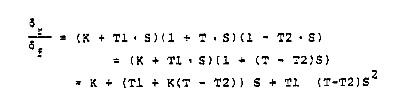

controller 17 can determine the rear wheel steering angle δr according to the above equation to control the rear wheel steering hydraulic system 300 (this includes parts indicated bynumerals 9 through 16 in Fig. 1). It will be thus noted that an actual rear wheel steered angleδ r can be obtained which corresponds to the mathematically calculated desired angle δr thereby achieving a desired degree of control unobtainable in the system indicated in Fig. 4. Further, since the above equation is not in the form of the fractional function of a linear expression / a linear expression, the digital filter and the high speed arithmetic unit are also unnecessary, reducing the manufacturing cost of the system. - When the rear wheel steering is controlled according to the the above described equation (10), the distance ℓ₃ which is, as mentioned previously, defined between the center of gravity of the vehicle and the position where the side slip angle becomes zero is varied based on the steered angle of the steering wheel ϑ, the angular velocity of the steering wheel ϑ̇, and the angular acceleration of the steering wheelto determine the desired rear wheel steering angle δr. Practically, it is preferable that the distance ℓ₃ is determined according to data acquired by experimentation based on the specific vehicles or types thereof. For example, while a vehicle is running on a road having continuous gentle curves, the values of the ϑ and the ϑ̇ become small. Thus, the relatively long distance ℓ₃ is provided and the rear wheel steering angle can be determined so that the position where the side slip becomes zero is defined relatively near the rear wheels to improve the cornering stability. Additionally, when a vehicle is running on a road having continuous tight curves, the values of the ϑ and the ϑ̇ become relatively great. Thus, the distance ℓ₃ is provided so that the position where the side slip becomes zero is defined relatively near the front wheels and the rear wheel steering angle is determined to improve the cornering stability. Further, when a vehicle is running on a mountain road on which a turning circle tends to vary, the value of the
 becomes great according to the variation. Thus, the distance ℓ₃ is determined according the variation of the turning circle to obtain a rear wheel steering angle so as to improve the cornering stability. It will be appreciated that the determination of the rear wheel steering angle based on the values of the ϑ, the ϑ̇, or the
 can provide highly stable cornering.
- As mentioned above, the control system according to the invention is adapted for determining the distance between the center of gravity and the position where side slip becomes zero based on the steered angle of a steering wheel, the angular velocity of steering thereof, or angular acceleration of steering thereof to control rear wheel steering angle. Therefore, the degree of freedom necessary for tuning a control constant for a rear wheel steering angle in order to improve the cornering properties of the vehicle increases and the responsiveness of the vehicle is improved relative to emergency handling to avoid danger and handling when the vehicle is slaloming. Additionally, high responsiveness can be obtained when the vehicle is running on a road in which the turning circle varies frequently.
Claims (7)
first sensing means for sensing a steered angle, steered angular velocity, and steered angular acceleration of the steering wheel of the vehicle to provide signals indicative thereof;
second sensing means for sensing a vehicle speed to provide a signal indicative thereof;
third means for determining a target steering angle for a rear wheel so as to vary the position where the side slip angle of the vehicle becomes zero with respect to the vehicle's center of gravity based on the signals from said first sensing means and said second sensing means; and
fourth means for controlling an actual steering angle for the rear wheel according to said target steering angle to achieve stable cornering.
δr / δf = K + τ · S + τ′ · S²
where
S : a Laplace's operator
K = C₁ {aMV² + C₂ℓ(ℓ₃ - b)} / C₂ {bMV² + C₁ℓ(ℓ₃ - a)}
τ = T1 + K(T - T2)
τ′ = T1(T - T2)
T1 = C₁V(aMℓ₃ - 1) / C₂{bMV² + C₁ℓ (ℓ₃ + a)}
T2 = V(bMℓ₃ + I) / bMV² + C₂ℓ(ℓ₃ + a)
M : a vehicle weight
I : a yaw moment of inertia
ℓ : a wheel base
ℓ₃ : a distance between the center of gravity and a position where the lateral slip angle becomes zero
a : a distance between the center of gravity and the center point between the front wheels
b : a distance between the center of gravity and the center point between the rear wheels
C₁ : cornering power of the two front wheels
C₂ : cornering power of the two rear wheels
V : vehicle speed
T : a first order lag time constant.
first sensing means for sensing a steered angle of a front wheel of the vehicle to provide signals indicative thereof;
second sensing means for sensing vehicle speed to provide a signal indicative thereof;
third means for determining a target steering angle for a rear wheel δr with respect to said steered angle of the front wheel δf according to the relation δr = (K + τ · S + τ′ · S²)δf based on the signals from said first sensing means and said second sensing means; and
fourth means for controlling an actual steering angle for the rear wheel according to said target steering angle δr to achieve stable cornering,
where
S : a Laplace's operator
K = C₁ {aMV² + C₂ℓ(ℓ₃ - b)} / C₂ {bMV² + C₁ℓ(ℓ₃ - a)}
τ = T1 + K(T - T2)
τ′ = T1(T - T2)
T1 = C₁V(aMℓ₃ - 1) / C₂{bMV² + C₁ℓ (ℓ₃ + a)}
T2 = V(bMℓ₃ + I) / bMV² + C₂ℓ(ℓ₃ + a)
M : vehicle weight
I : yaw moment of inertia
ℓ : wheel base
ℓ₃ : distance between the center of gravity and a position where the lateral slip angle becomes zero
a : distance between the center of gravity and the center point between the front wheels
b : distance between the center of gravity and the center point between the rear wheels
C₁ : cornering power of the two front wheels
C₂ : cornering power of the two rear wheels
V : vehicle speed
T : a first order lag time constant.
Applications Claiming Priority (2)
| Application Number | Priority Date | Filing Date | Title |
|---|---|---|---|
| JP63252922A JP2557961B2 (en) | 1988-10-08 | 1988-10-08 | Rear wheel steering angle control device |
| JP252922/88 | 1988-10-08 |
Publications (3)
| Publication Number | Publication Date |
|---|---|
| EP0363846A2 true EP0363846A2 (en) | 1990-04-18 |
| EP0363846A3 EP0363846A3 (en) | 1990-11-28 |
| EP0363846B1 EP0363846B1 (en) | 1994-02-16 |
Family
ID=17244036
Family Applications (1)
| Application Number | Title | Priority Date | Filing Date |
|---|---|---|---|
| EP89118627A Expired - Lifetime EP0363846B1 (en) | 1988-10-08 | 1989-10-06 | Rear wheel-steering angle control-system for vehicle |
Country Status (4)
| Country | Link |
|---|---|
| US (1) | US5105899A (en) |
| EP (1) | EP0363846B1 (en) |
| JP (1) | JP2557961B2 (en) |
| DE (1) | DE68913125T2 (en) |
Cited By (3)
| Publication number | Priority date | Publication date | Assignee | Title |
|---|---|---|---|---|
| FR2660275A1 (en) * | 1990-03-28 | 1991-10-04 | Nissan Motor | REAR WHEEL ROTATION SYSTEM FOR A MOTOR VEHICLE. |
| US5105899A (en) * | 1988-10-08 | 1992-04-21 | Nissan Motor Company, Limited | Rear wheel steering angle control system for vehicles |
| EP1052161A3 (en) * | 1999-05-11 | 2003-01-02 | Koyo Seiko Co., Ltd. | Steering system for motor vehicles |
Families Citing this family (10)
| Publication number | Priority date | Publication date | Assignee | Title |
|---|---|---|---|---|
| JP3001294B2 (en) * | 1991-07-10 | 2000-01-24 | マツダ株式会社 | Vehicle rear wheel steering system |
| JP2803487B2 (en) * | 1992-09-22 | 1998-09-24 | 三菱自動車工業株式会社 | Fuzzy control type electronic control power steering device |
| DE4325413C2 (en) * | 1993-07-29 | 1995-05-18 | Daimler Benz Ag | Method for determining the behavior of characteristic quantities |
| DE4341636A1 (en) * | 1993-12-07 | 1995-06-08 | Zahnradfabrik Friedrichshafen | Vehicle with steerable front and rear wheels |
| JP2001158372A (en) * | 1999-12-03 | 2001-06-12 | Honda Motor Co Ltd | Vehicle behavior control device |
| US6560524B2 (en) * | 2001-09-26 | 2003-05-06 | General Motors Corporation | Integration of rear wheel steering with vehicle stability enhancement system |
| DE10351908A1 (en) * | 2003-11-06 | 2005-06-09 | Bayerische Motoren Werke Ag | Motor vehicle with steerable front wheels and a steering function on the rear wheels |
| WO2011059050A1 (en) * | 2009-11-16 | 2011-05-19 | 本田技研工業株式会社 | Rear wheel steering control device |
| DE102021201141A1 (en) * | 2021-02-08 | 2022-08-11 | Continental Automotive Gmbh | Control device and method for steering angle control of a vehicle |
| KR102662632B1 (en) * | 2022-01-14 | 2024-05-03 | 현대모비스 주식회사 | Apparatus for 4wheel independent steering and control method thereof |
Family Cites Families (10)
| Publication number | Priority date | Publication date | Assignee | Title |
|---|---|---|---|---|
| JPS5787759A (en) * | 1980-11-18 | 1982-06-01 | Nissan Motor Co Ltd | Method of steering vehicle |
| JPS61175179A (en) * | 1985-01-31 | 1986-08-06 | Nissan Motor Co Ltd | Steering angle control device for vehicle |
| AU583883B2 (en) * | 1985-01-24 | 1989-05-11 | Honda Giken Kogyo Kabushiki Kaisha | Front and rear wheel steering device |
| US4706771A (en) * | 1985-01-31 | 1987-11-17 | Nissan Motor Co., Ltd. | Vehicle steering control system using desired vehicle model |
| DE3661472D1 (en) * | 1985-04-13 | 1989-01-26 | Nissan Motor | Vehicle control system for controlling side slip angle and yaw rate gain |
| US4706979A (en) * | 1985-07-12 | 1987-11-17 | Nissan Motor Co., Ltd. | Steering control system for wheeled vehicle |
| JPH0719951Y2 (en) * | 1985-07-30 | 1995-05-10 | 三菱自動車工業株式会社 | Rear wheel steering system |
| FR2608545B1 (en) * | 1986-12-19 | 1990-08-31 | Peugeot | DEVICE FOR CORRECTING THE ANGLE OF ATTITUDE OF A MOTOR VEHICLE |
| JPS6475574A (en) * | 1987-09-18 | 1989-03-22 | Toray Industries | Coating for cation electrodeposition |
| JP2557961B2 (en) * | 1988-10-08 | 1996-11-27 | 日産自動車株式会社 | Rear wheel steering angle control device |
-
1988
- 1988-10-08 JP JP63252922A patent/JP2557961B2/en not_active Expired - Lifetime
-
1989
- 1989-10-06 EP EP89118627A patent/EP0363846B1/en not_active Expired - Lifetime
- 1989-10-06 DE DE68913125T patent/DE68913125T2/en not_active Expired - Fee Related
- 1989-10-10 US US07/419,161 patent/US5105899A/en not_active Expired - Fee Related
Cited By (7)
| Publication number | Priority date | Publication date | Assignee | Title |
|---|---|---|---|---|
| US5105899A (en) * | 1988-10-08 | 1992-04-21 | Nissan Motor Company, Limited | Rear wheel steering angle control system for vehicles |
| FR2660275A1 (en) * | 1990-03-28 | 1991-10-04 | Nissan Motor | REAR WHEEL ROTATION SYSTEM FOR A MOTOR VEHICLE. |
| GB2243127A (en) * | 1990-03-28 | 1991-10-23 | Nissan Motor | Rear wheel steering system for automotive vehicle |
| US5186273A (en) * | 1990-03-28 | 1993-02-16 | Nissan Motor Co., Ltd. | Rear wheel steering system for automotive vehicle |
| GB2243127B (en) * | 1990-03-28 | 1993-11-17 | Nissan Motor | Rear wheel steering system for automotive vehicle |
| EP1052161A3 (en) * | 1999-05-11 | 2003-01-02 | Koyo Seiko Co., Ltd. | Steering system for motor vehicles |
| EP1544079A3 (en) * | 1999-05-11 | 2006-04-12 | Koyo Seiko Co., Ltd. | Steering system for motor vehicles |
Also Published As
| Publication number | Publication date |
|---|---|
| US5105899A (en) | 1992-04-21 |
| JP2557961B2 (en) | 1996-11-27 |
| DE68913125D1 (en) | 1994-03-24 |
| EP0363846A3 (en) | 1990-11-28 |
| EP0363846B1 (en) | 1994-02-16 |
| JPH02102874A (en) | 1990-04-16 |
| DE68913125T2 (en) | 1994-06-16 |
Similar Documents
| Publication | Publication Date | Title |
|---|---|---|
| US5964819A (en) | Vehicle yawing behavior control apparatus | |
| US4418780A (en) | Method of steering a wheeled vehicle having at least two pairs of steerable road wheels | |
| US4441572A (en) | Method and a system for steering a wheeled vehicle | |
| US4949261A (en) | Steering control system for wheeled vehicle | |
| EP0363846B1 (en) | Rear wheel-steering angle control-system for vehicle | |
| JP2578142B2 (en) | Auxiliary steering system for vehicles | |
| JPS61196873A (en) | Front/rear wheel steering device for vehicle | |
| US20160129932A1 (en) | Steering system for wheeled land vehicle | |
| JPH0825470B2 (en) | Rear wheel rudder angle control method | |
| US4947326A (en) | Rear wheel steer angle control system for vehicle | |
| EP0384400B1 (en) | Rear wheel steering angle control system for vehicle | |
| US5180026A (en) | Rear wheel steering angle control system for vehicle | |
| JP2520144B2 (en) | Rear wheel steering angle control device | |
| JP3097191B2 (en) | Vehicle steering reaction control system | |
| JPH0561147B2 (en) | ||
| JP2515731Y2 (en) | Steerable trailer | |
| JP2502761B2 (en) | Four-wheel steering system for vehicles | |
| JP2528918B2 (en) | Rear wheel steering angle control device | |
| JP2520146B2 (en) | Rear wheel steering angle control device | |
| JPH0547429B2 (en) | ||
| JPS60191876A (en) | Controlling method of steerage for vehicles | |
| JP2539035B2 (en) | Rear wheel steering system | |
| JP2505251B2 (en) | Vehicle auxiliary steering system | |
| JPS62227873A (en) | Four wheel steering device for vehicle | |
| JPH01101434A (en) | Detecting device for road surface friction coefficient |
Legal Events
| Date | Code | Title | Description |
|---|---|---|---|
| PUAI | Public reference made under article 153(3) epc to a published international application that has entered the european phase |
Free format text: ORIGINAL CODE: 0009012 |
|
| 17P | Request for examination filed |
Effective date: 19891006 |
|
| AK | Designated contracting states |
Kind code of ref document: A2 Designated state(s): DE GB |
|
| PUAL | Search report despatched |
Free format text: ORIGINAL CODE: 0009013 |
|
| AK | Designated contracting states |
Kind code of ref document: A3 Designated state(s): DE GB |
|
| 17Q | First examination report despatched |
Effective date: 19910912 |
|
| GRAA | (expected) grant |
Free format text: ORIGINAL CODE: 0009210 |
|
| AK | Designated contracting states |
Kind code of ref document: B1 Designated state(s): DE GB |
|
| REF | Corresponds to: |
Ref document number: 68913125 Country of ref document: DE Date of ref document: 19940324 |
|
| PLBE | No opposition filed within time limit |
Free format text: ORIGINAL CODE: 0009261 |
|
| STAA | Information on the status of an ep patent application or granted ep patent |
Free format text: STATUS: NO OPPOSITION FILED WITHIN TIME LIMIT |
|
| 26N | No opposition filed | ||
| PGFP | Annual fee paid to national office [announced via postgrant information from national office to epo] |
Ref country code: GB Payment date: 19981009 Year of fee payment: 10 |
|
| PGFP | Annual fee paid to national office [announced via postgrant information from national office to epo] |
Ref country code: DE Payment date: 19981012 Year of fee payment: 10 |
|
| PG25 | Lapsed in a contracting state [announced via postgrant information from national office to epo] |
Ref country code: GB Free format text: LAPSE BECAUSE OF NON-PAYMENT OF DUE FEES Effective date: 19991006 |
|
| GBPC | Gb: european patent ceased through non-payment of renewal fee |
Effective date: 19991006 |
|
| PG25 | Lapsed in a contracting state [announced via postgrant information from national office to epo] |
Ref country code: DE Free format text: LAPSE BECAUSE OF NON-PAYMENT OF DUE FEES Effective date: 20000801 |