EP0363867B1 - Appareil d'enregistrement et de reproduction, en particulier répondeur téléphonique - Google Patents
Appareil d'enregistrement et de reproduction, en particulier répondeur téléphonique Download PDFInfo
- Publication number
- EP0363867B1 EP0363867B1 EP89118699A EP89118699A EP0363867B1 EP 0363867 B1 EP0363867 B1 EP 0363867B1 EP 89118699 A EP89118699 A EP 89118699A EP 89118699 A EP89118699 A EP 89118699A EP 0363867 B1 EP0363867 B1 EP 0363867B1
- Authority
- EP
- European Patent Office
- Prior art keywords
- recording
- operating
- control device
- playback device
- control
- Prior art date
- Legal status (The legal status is an assumption and is not a legal conclusion. Google has not performed a legal analysis and makes no representation as to the accuracy of the status listed.)
- Expired - Lifetime
Links
- 238000011156 evaluation Methods 0.000 claims description 5
- 238000000034 method Methods 0.000 claims description 4
- 230000008569 process Effects 0.000 claims description 3
- 238000012806 monitoring device Methods 0.000 claims description 2
- 230000003213 activating effect Effects 0.000 abstract 1
- 238000012544 monitoring process Methods 0.000 abstract 1
- 230000006870 function Effects 0.000 description 34
- 230000001960 triggered effect Effects 0.000 description 6
- 230000008901 benefit Effects 0.000 description 3
- 238000012217 deletion Methods 0.000 description 3
- 230000037430 deletion Effects 0.000 description 3
- 238000010586 diagram Methods 0.000 description 2
- 239000004065 semiconductor Substances 0.000 description 2
- 230000004913 activation Effects 0.000 description 1
- 238000013475 authorization Methods 0.000 description 1
- 230000006835 compression Effects 0.000 description 1
- 238000007906 compression Methods 0.000 description 1
- 238000013461 design Methods 0.000 description 1
- 239000011888 foil Substances 0.000 description 1
- 230000006386 memory function Effects 0.000 description 1
- 230000007704 transition Effects 0.000 description 1
Images
Classifications
-
- H—ELECTRICITY
- H04—ELECTRIC COMMUNICATION TECHNIQUE
- H04M—TELEPHONIC COMMUNICATION
- H04M1/00—Substation equipment, e.g. for use by subscribers
- H04M1/64—Automatic arrangements for answering calls; Automatic arrangements for recording messages for absent subscribers; Arrangements for recording conversations
- H04M1/65—Recording arrangements for recording a message from the calling party
Definitions
- the invention relates to a recording / playback device according to the preamble of patent claim 1.
- Recording and playback devices usually contain a control device and an operating device which are used to control operating functions, e.g. Record and playback operations operated by the user.
- Such recording and playback devices are, for example, dictation machines, tape recorders, telephone answering machines, video recorders, camcorders etc. In all of these different recording and playback devices, both the requirement for high functional reliability and the requirement for the simplest possible operation by the user must be met.
- the operating functions or operating positions: recording, off / stop, playback and rewind are controlled by the user by moving the control button into the different operating positions.
- recording, off / stop, playback and rewind are controlled by the user by moving the control button into the different operating positions.
- the "off / stop” operating position is locked (the control button in the "off / stop” operating position snaps into a recess provided on the device). Nevertheless, the case can occur that the locking is triggered by overcoming the spring force of the compression spring.
- DE-B 23 02 954 discloses a combination of slide, pusher and locking pin in order to increase the functional reliability, above all to avoid the inadvertent adjustment of the slide to the "receiving" operating position. If the slide is to be brought into the “pickup” operating position, the user must actuate both the pusher and the locking pin arranged in the pusher. Such a mechanical interlock circuit requires a lot of circuitry and is also not easy for the user to use.
- an electrical locking circuit can also be provided in the recording / playback device.
- a locking circuit is known from the magazine "Grundig Technical Information 3/1978, pages 172, 173 and 190".
- the locking circuit stores the commands coming from the keyboard, which ensures that only one command is accepted at a time. To avoid undesired functional sequences, they are locked against each other.
- a display device e.g. LEDs shows whether the command has been accepted or whether the transition to the new function is blocked.
- the locking and unlocking of the keyboard can also be controlled automatically by the control device (module), as is explained in more detail in the above-mentioned magazine on page 173, middle column, section "automatic sequence at the end of the line". If the mark (switching foil) attached in front of both ends of the belt is passed, the control device locks the keyboard and the running function is interrupted. When the tape has come to a standstill, it is moved back in the opposite direction, which brings the tape end mark back to the sensor. Then the keyboard is released again.
- the control device module
- interlocking circuit and control device known from the above-mentioned magazine already has a relatively high degree of functional reliability, nevertheless, unintentional actuation of a button, e.g. the stop button, an automatic functional sequence, e.g. Recording by means of a timer, disrupted or an undesired functional sequence initiated.
- a button e.g. the stop button
- an automatic functional sequence e.g. Recording by means of a timer, disrupted or an undesired functional sequence initiated.
- An indication that the user can control the keypad in the locked state and unlock it again by entering a command cannot be found in the above-mentioned journal article.
- a locking circuit is known in which the time sequence and the input of certain control commands are monitored during a waiting time predetermined by the timing element by means of a timing element with memory function and digital logic circuits. The possibility of unlocking controlled by the user is not apparent from the locking circuit known therefrom.
- EP-A2-0 153 602 a command entry in a microprocessor-controlled video recorder is known, in which special functions are triggered by entering a code number and a point in time. This makes it possible, for example, to use it without authorization to prevent the device or to lock certain special functions or operating functions, such as the recording function.
- the unlocking ie the termination of the special functions, is carried out either by re-entering the code number or by the passage of time.
- a command input requires a special numeric keypad as well as corresponding programs of the microprocessor for controlling both the operating functions, e.g. start, stop, fast forward, fast reverse, pause, search, recording, playback, etc. on the control panel as well as the special functions, e.g. unlocking, service status etc.
- the invention has for its object to design a recording and playback device so that the user can trigger and end both operating functions and special functions of the recording and playback device by the controls.
- the recording and playback device has the advantage that both the operating functions and special functions can be used with one and the same operating device can be triggered and ended. A high level of functional reliability is guaranteed even during the fully automatic operation of the device, in particular the unintentional deletion of a recording is reliably prevented. The termination of special functions by the user is made possible in a surprisingly simple manner, so that the recording and playback device according to the invention is also very easy to use.
- a microprocessor is arranged in the recording and playback device and this takes over the control of the special functions, the additional circuitry is particularly low.
- the embodiments of the recording and playback device according to patent claims 3 and 4 have the advantage that operator guidance is made possible.
- the display of the unlocking process immediately informs the user that his command entry has led to the goal and that the special function has ended.
- control element is designed as a button / display element according to claim 5, the user is informed in a simple manner whether an operating function or a special function is triggered when the control element is actuated.
- the embodiments of the recording and playback device according to claims 6, 7 and 8 have the advantage that counter readings can be easily evaluated by the control device or the microprocessor.
- the recording and playback device is described below for the telephone answering machine application.
- it can be used with all recording and playback devices, for which operating functions and special functions have one and the same Controls are controlled by the user and where a high level of functional reliability and ease of use are required.
- existing devices in the device are used anyway, for example, to obtain protection against accidental deletion of the texts (e.g. message texts and announcement-rejection texts) with a telephone answering machine (recording lock).
- the activation of the recording lock is preferably controlled by a control device (for example a microprocessor) arranged in the device and the user receives a corresponding message when the (or the) control element is actuated. Switching off the recording lock can be controlled in a surprisingly simple manner by the user and the operating process is acknowledged if this has led to success.
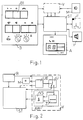
- FIG. 1 shows the block diagram of a telephone answering machine with an operating device B and a control device ST connected to it for controlling the functional devices F arranged in the device, for example a magnetic tape memory.
- a second connection leads via the locking circuit V to the control device ST.
- a display device A and an acoustic reproduction device H are also connected to the control device ST.
- Telephone answering machines have different operating modes e.g. "Call Answer Only”; Answering calls with recording and remote inquiry ";” Listening to recorded messages “and” Dictation mode ".
- the user To control the various operating functions, the user must operate the corresponding operating elements on the operating device.
- short-stroke keys are preferably used as operating elements.
- Fig. 1 the various controls are shown with their associated symbols.
- the record button B1 the user can both record the respective texts and use the telephone answering machine as a dictation device.
- the new recording option is automatically blocked, i.e. a key command is not accepted and acknowledged. This automatic locking is not effective unless such text is stored on the tape or in a digital semiconductor memory. If in the locked state a key command is accidentally given for the new admission, the display A indicates that an unlocking must first take place.
- the record button B1 must be pressed and held for several seconds.
- the unlocking is confirmed by an acoustic signal emitted at the acoustic reproduction device H.
- the further key actuation for control in the different operating modes and operating functions is now possible in the usual way.
- the record button B1 is also used to record a message on the tape or in the digital semiconductor memory or for a possible one Dictation mode is used, and the decision as to whether the text or a dictation should be recorded is made only by pressing the button below, the lock is only effective for the respective text recording. Dictations can be recorded without delay.
- the display device A is used for operator guidance.
- the display device A shows the user various information, e.g. text selection display, call counting, message counting, remaining playing time, error display, code display, display during tape positioning, time keeping in seconds, etc. If certain special functions are triggered in the recording / playback device, these can be displayed on the display device A. will. Furthermore, the user can be guided to end the special function. For example, the display "F9" indicates to the user that the text has already been discussed and that the special function "recording lock" has to be released for new recording.
- the time sequence can be indicated in the display device by time counting and / or the termination of the special function can be made audible by a signal tone.
- the same procedure can be used if one or more operating elements have to be actuated several times and / or in a specific sequence for unlocking. The user then receives an indication of which control element and how often this is to be operated.
- control of the operating and special functions can also be taken over by a microprocessor which, in a program-controlled manner, locks and unlocks the operating element or triggers or ends the special function.
- the interlock circuit V contains a changeover switch U which is connected on the one hand to the operating device B and on the other hand, controlled by the control device ST, switches between the latter and an evaluation device AW connected to the control device ST.
- the evaluation device AW contains a timer Z and a logic circuit VS, preferably an AND gate, connected to its output. The input of the timing element Z and a further input of the AND gate VS is connected to the changeover switch U, the output of the logic circuit (VS) being connected to the control device ST.
- a monitoring device UE connected to the microphone M monitors. If the specified limit values are adhered to, control is carried out by the control device ST, the evaluation device AW connected to the changeover switch U, as a result of which the corresponding operating element, for example the recording button B1, is locked. To unlock, the user must now hold down the recording button B1 for a certain period of time, this period of time being determined by the timer Z. If this time condition is met, the control circuit ST reverses.
Landscapes
- Engineering & Computer Science (AREA)
- Signal Processing (AREA)
- Telephone Function (AREA)
- Input From Keyboards Or The Like (AREA)
- Telephonic Communication Services (AREA)
- Telephone Set Structure (AREA)
- Selective Calling Equipment (AREA)
Claims (10)
- Appareil d'enregistrement-reproduction, notamment répondeur téléphonique, comportant un dispositif de service (D) et un dispositif de commande (ST) pour commander les dispositifs fonctionnels (F) disposés dans l'appareil, caractérisé par le fait qu'à au moins un élément de service (B1) est associé un circuit de verrouillage (V), qui est relié à l'élément de service (B1) et au dispositif de commande (ST), que le circuit de verrouillage (V) peut être activé manuellement et/ou automatiquement au moyen d'une instruction de commande, par le dispositif de commande (ST) et que pour le déverrouillage de l'élément de service (B1) par le circuit de verrouillage (V), la durée de l'actionnement de l'élément de service (B1) est évaluée.
- Appareil d'enregistrement-reproduction selon la revendication 1, caractérisé en ce qu'on utilise comme dispositif de commande (ST) et comme circuit de verrouillage (V) un microprocesseur, qui verrouille l'élément de service (B1) d'une manière commandée par un programme, par le fait que pendant l'enregistrement, aussi bien le niveau que la variation dans le temps des signaux introduits sont contrôlés par le microprocesseur et que, lors du respect de valeurs limites prédéterminées pour le niveau et la variation dans le temps, la fonction d'enregistrement est verrouillée automatiquement et que pour le déverrouillage, le microprocesseur évalue la durée de l'actionnement de l'élément de service (B1).
- Appareil d'enregistrement-reproduction selon la revendication 1 ou 2, caractérisé par le fait qu'au dispositif de commande (ST) ou au microprocesseur est relié un dispositif d'affichage (A) et/ou un dispositif de reproduction acoustique (H), ce qui a pour effet que lors de l'actionnement de l'élément de service (B1), l'état de verrouillage peut être indiqué optiquement et/ou acoustiquement.
- Appareil d'enregistrement-reproduction selon la revendication 3, caractérisé en ce que l'opération de déverrouillage peut être indiquée optiquement et/ou acoustiquement.
- Appareil d'enregistrement-reproduction selon la revendication 3 ou 4, caractérisé en ce que l'élément de service (B1) est réalisé sous la forme d'un élément de manipulation/affichage et que l'état de verrouillage et/ou l'état de déverrouillage peut être affiché optiquement.
- Appareil d'enregistrement-reproduction selon la revendication 1 ou 2, caractérisé en ce que le dispositif de commande (ST) et le microprocesseur évaluent, pour le déverrouillage, le nombre des actionnements de l'élément de service (B1).
- Appareil d'enregistrement-reproduction selon la revendication 1 ou 2, caractérisé en ce que pour la commande dans l'état de verrouillage, le dispositif de commande (ST) et le microprocesseur évaluent la succession des éléments de service actionnés.
- Appareil d'enregistrement-reproduction selon la revendication 7, caractérisé en ce que le dispositif de commande (ST) du microprocesseur évalue, pour le déverrouillage, la succession et/ou le nombre des actionnements des éléments de service.
- Appareil d'enregistrement-reproduction selon la revendication 1, caractérisé en ce que le circuit de verrouillage (B1) contient un dispositif de contrôle (UE) et un commutateur (U), qui est relié au dispositif de service (B) et que, sous la commande du dispositif de commande (ST), le commutateur (U) est commuté entre le dispositif de commande (ST) et un dispositif d'évaluation (AW) relié au dispositif de commande (ST).
- Appareil d'enregistrement-reproduction selon la revendication 9, caractérisé en ce que le dispositif d'évaluation (AW) est constitué par une minuterie (Z) et par un circuit combinatoire (VS) relié à la sortie de cette minuterie, l'entrée de la minuterie (Z) et une autre entrée du circuit combinatoire (VS) étant reliées au commutateur (U), et que la sortie du circuit combinatoire (VS) est reliée au dispositif de commande (ST).
Applications Claiming Priority (2)
| Application Number | Priority Date | Filing Date | Title |
|---|---|---|---|
| DE3834303A DE3834303A1 (de) | 1988-10-08 | 1988-10-08 | Aufnahme-wiedergabegeraet, insbesondere telefonanrufbeantworter |
| DE3834303 | 1988-10-08 |
Publications (3)
| Publication Number | Publication Date |
|---|---|
| EP0363867A2 EP0363867A2 (fr) | 1990-04-18 |
| EP0363867A3 EP0363867A3 (fr) | 1992-01-08 |
| EP0363867B1 true EP0363867B1 (fr) | 1994-08-31 |
Family
ID=6364684
Family Applications (1)
| Application Number | Title | Priority Date | Filing Date |
|---|---|---|---|
| EP89118699A Expired - Lifetime EP0363867B1 (fr) | 1988-10-08 | 1989-10-08 | Appareil d'enregistrement et de reproduction, en particulier répondeur téléphonique |
Country Status (3)
| Country | Link |
|---|---|
| EP (1) | EP0363867B1 (fr) |
| AT (1) | ATE110906T1 (fr) |
| DE (2) | DE3834303A1 (fr) |
Families Citing this family (1)
| Publication number | Priority date | Publication date | Assignee | Title |
|---|---|---|---|---|
| AT404237B (de) | 1995-11-30 | 1998-09-25 | Painsith Hermann Dipl Ing | Plattenförmiges aufnahmegehäuse für gebrauchs- und/oder verbrauchsgegenstände |
Family Cites Families (8)
| Publication number | Priority date | Publication date | Assignee | Title |
|---|---|---|---|---|
| DE1772078A1 (de) * | 1966-09-03 | 1971-08-19 | Sued Atlas Werke Gmbh | Steuerungseinrichtung fuer Diktiergeraete fuer das Umschalten von Wiedergabe zur Aufnahme |
| JPS5671868A (en) * | 1979-11-14 | 1981-06-15 | Canon Inc | Video recorder |
| GB2096381B (en) * | 1981-04-03 | 1985-03-20 | Pioneer Electronic Corp | Device for detecting a non-recorded segment on magnetic tape |
| JPS60132449A (ja) * | 1983-12-21 | 1985-07-15 | Hashimoto Corp | 電話自動応対録音装置 |
| JPS60230754A (ja) * | 1984-04-28 | 1985-11-16 | Hashimoto Corp | 操作容易な電話自動応対録音装置 |
| JPS6170841A (ja) * | 1984-09-13 | 1986-04-11 | Hashimoto Corp | 操作容易な電話自動応対録音装置 |
| JPS61244157A (ja) * | 1985-04-20 | 1986-10-30 | Hashimoto Corp | 操作容易な電話等の自動録音再生装置 |
| US4764823A (en) * | 1986-12-12 | 1988-08-16 | Eastman Kodak Company | Soft erase protection for video cassettes |
-
1988
- 1988-10-08 DE DE3834303A patent/DE3834303A1/de not_active Withdrawn
-
1989
- 1989-10-08 DE DE58908273T patent/DE58908273D1/de not_active Expired - Lifetime
- 1989-10-08 EP EP89118699A patent/EP0363867B1/fr not_active Expired - Lifetime
- 1989-10-08 AT AT89118699T patent/ATE110906T1/de not_active IP Right Cessation
Also Published As
| Publication number | Publication date |
|---|---|
| ATE110906T1 (de) | 1994-09-15 |
| EP0363867A2 (fr) | 1990-04-18 |
| DE58908273D1 (de) | 1994-10-06 |
| DE3834303A1 (de) | 1990-04-12 |
| EP0363867A3 (fr) | 1992-01-08 |
Similar Documents
| Publication | Publication Date | Title |
|---|---|---|
| DE4023193A1 (de) | Steuersystem fuer ein cd-abspielgeraet, insbesondere eine musikbox fuer cds | |
| DE3602068A1 (de) | Automatischer programmwaehler fuer ein videobandgeraet | |
| DE2330896C2 (de) | Aufzeichnungs- und/oder Wiedergabegerät für Magnetbandkassetten | |
| EP0212389B1 (fr) | Récepteur de télévision | |
| DE3042842C2 (de) | Video-System | |
| EP0363867B1 (fr) | Appareil d'enregistrement et de reproduction, en particulier répondeur téléphonique | |
| DE2248417C2 (de) | Gerät zur automatischen Telephonanrufbeantwortung | |
| DE2549908A1 (de) | Magnetbandaufnahme- und/oder -wiedergabegeraet, insbesondere diktiergeraet mit vereinfachtem redigieren | |
| DE3406890C2 (de) | Befehlseingabe bei einem mikroprozessorgesteuerten Videorecorder | |
| DE2901241A1 (de) | Automatischer anrufbeantworter | |
| DE2635002C3 (de) | Ein- und Ausblendeinrichtung an einem Magnetbandgerät | |
| DE3702331C2 (fr) | ||
| DE2346349C3 (de) | Tonaufnahmegerät | |
| DE2818122A1 (de) | Tonbandgeraet | |
| DE2718137A1 (de) | Kassettengeraet | |
| DE4313059A1 (de) | Verfahren und Vorrichtung zur Aufnahme/Abspielen von Videokassetten | |
| DE2610505A1 (de) | Magnetbandgeraet | |
| EP0503519B1 (fr) | Enregistreur vidéo avec registre de mémorisation de la table des matières d'une pluralité de cassettes magnétiques | |
| DE2807522A1 (de) | Kassettentonbandgeraet mit zwei wickelmotoren | |
| DE2748629C2 (fr) | ||
| DE3123400C2 (de) | Steuervorrichtung für die Betriebsarten eines Magnetbandrecorders | |
| EP1213718B1 (fr) | Dispositif d'introduction de commandes de fonctionnement dans un appareil d'enregistrement/reproduction | |
| DE4103582C2 (fr) | ||
| DE2555380A1 (de) | Telefonanrufbeantworter | |
| DE2629894B1 (de) | Schaltungsanordnung zum loeschen eines ganz oder teilweise mit daten beschriebenen magnetbandes |
Legal Events
| Date | Code | Title | Description |
|---|---|---|---|
| PUAI | Public reference made under article 153(3) epc to a published international application that has entered the european phase |
Free format text: ORIGINAL CODE: 0009012 |
|
| AK | Designated contracting states |
Kind code of ref document: A2 Designated state(s): AT BE CH DE FR GB LI SE |
|
| PUAL | Search report despatched |
Free format text: ORIGINAL CODE: 0009013 |
|
| AK | Designated contracting states |
Kind code of ref document: A3 Designated state(s): AT BE CH DE FR GB LI SE |
|
| 17P | Request for examination filed |
Effective date: 19920319 |
|
| 17Q | First examination report despatched |
Effective date: 19940120 |
|
| GRAA | (expected) grant |
Free format text: ORIGINAL CODE: 0009210 |
|
| AK | Designated contracting states |
Kind code of ref document: B1 Designated state(s): AT BE CH DE FR GB LI SE |
|
| PG25 | Lapsed in a contracting state [announced via postgrant information from national office to epo] |
Ref country code: BE Effective date: 19940831 |
|
| REF | Corresponds to: |
Ref document number: 110906 Country of ref document: AT Date of ref document: 19940915 Kind code of ref document: T |
|
| REF | Corresponds to: |
Ref document number: 58908273 Country of ref document: DE Date of ref document: 19941006 |
|
| PG25 | Lapsed in a contracting state [announced via postgrant information from national office to epo] |
Ref country code: AT Effective date: 19941008 |
|
| PG25 | Lapsed in a contracting state [announced via postgrant information from national office to epo] |
Ref country code: CH Effective date: 19941031 Ref country code: LI Effective date: 19941031 |
|
| PG25 | Lapsed in a contracting state [announced via postgrant information from national office to epo] |
Ref country code: SE Effective date: 19941130 |
|
| GBT | Gb: translation of ep patent filed (gb section 77(6)(a)/1977) |
Effective date: 19941129 |
|
| ET | Fr: translation filed | ||
| REG | Reference to a national code |
Ref country code: CH Ref legal event code: PL |
|
| PLBE | No opposition filed within time limit |
Free format text: ORIGINAL CODE: 0009261 |
|
| STAA | Information on the status of an ep patent application or granted ep patent |
Free format text: STATUS: NO OPPOSITION FILED WITHIN TIME LIMIT |
|
| 26N | No opposition filed | ||
| REG | Reference to a national code |
Ref country code: GB Ref legal event code: 746 Effective date: 19951002 |
|
| REG | Reference to a national code |
Ref country code: FR Ref legal event code: D6 |
|
| REG | Reference to a national code |
Ref country code: FR Ref legal event code: CD |
|
| REG | Reference to a national code |
Ref country code: FR Ref legal event code: TP |
|
| REG | Reference to a national code |
Ref country code: GB Ref legal event code: IF02 |
|
| REG | Reference to a national code |
Ref country code: GB Ref legal event code: 732E |
|
| REG | Reference to a national code |
Ref country code: FR Ref legal event code: TP |
|
| PGFP | Annual fee paid to national office [announced via postgrant information from national office to epo] |
Ref country code: DE Payment date: 20081103 Year of fee payment: 20 |
|
| PGFP | Annual fee paid to national office [announced via postgrant information from national office to epo] |
Ref country code: FR Payment date: 20081024 Year of fee payment: 20 |
|
| PGFP | Annual fee paid to national office [announced via postgrant information from national office to epo] |
Ref country code: GB Payment date: 20081028 Year of fee payment: 20 |
|
| REG | Reference to a national code |
Ref country code: GB Ref legal event code: PE20 Expiry date: 20091007 |
|
| PG25 | Lapsed in a contracting state [announced via postgrant information from national office to epo] |
Ref country code: GB Free format text: LAPSE BECAUSE OF EXPIRATION OF PROTECTION Effective date: 20091007 |