EP0363957A2 - Serrure mécanique - Google Patents
Serrure mécanique Download PDFInfo
- Publication number
- EP0363957A2 EP0363957A2 EP89118981A EP89118981A EP0363957A2 EP 0363957 A2 EP0363957 A2 EP 0363957A2 EP 89118981 A EP89118981 A EP 89118981A EP 89118981 A EP89118981 A EP 89118981A EP 0363957 A2 EP0363957 A2 EP 0363957A2
- Authority
- EP
- European Patent Office
- Prior art keywords
- code
- locking device
- fixers
- cross
- housing
- Prior art date
- Legal status (The legal status is an assumption and is not a legal conclusion. Google has not performed a legal analysis and makes no representation as to the accuracy of the status listed.)
- Withdrawn
Links
Images

Classifications
-
- E—FIXED CONSTRUCTIONS
- E05—LOCKS; KEYS; WINDOW OR DOOR FITTINGS; SAFES
- E05B—LOCKS; ACCESSORIES THEREFOR; HANDCUFFS
- E05B19/00—Keys; Accessories therefor
- E05B19/18—Keys adjustable before use
-
- E—FIXED CONSTRUCTIONS
- E05—LOCKS; KEYS; WINDOW OR DOOR FITTINGS; SAFES
- E05B—LOCKS; ACCESSORIES THEREFOR; HANDCUFFS
- E05B27/00—Cylinder locks or other locks with tumbler pins or balls that are set by pushing the key in
- E05B27/02—Cylinder locks or other locks with tumbler pins or balls that are set by pushing the key in operated by the edge of the key
- E05B27/08—Cylinder locks or other locks with tumbler pins or balls that are set by pushing the key in operated by the edge of the key arranged axially
- E05B27/086—Cylinder locks or other locks with tumbler pins or balls that are set by pushing the key in operated by the edge of the key arranged axially of the bar-tumbler type, the bars having slots or protrusions in alignment upon opening the lock
-
- Y—GENERAL TAGGING OF NEW TECHNOLOGICAL DEVELOPMENTS; GENERAL TAGGING OF CROSS-SECTIONAL TECHNOLOGIES SPANNING OVER SEVERAL SECTIONS OF THE IPC; TECHNICAL SUBJECTS COVERED BY FORMER USPC CROSS-REFERENCE ART COLLECTIONS [XRACs] AND DIGESTS
- Y10—TECHNICAL SUBJECTS COVERED BY FORMER USPC
- Y10T—TECHNICAL SUBJECTS COVERED BY FORMER US CLASSIFICATION
- Y10T70/00—Locks
- Y10T70/70—Operating mechanism
- Y10T70/7441—Key
- Y10T70/7486—Single key
- Y10T70/7508—Tumbler type
- Y10T70/752—Sliding tumblers
- Y10T70/7531—Transverse
-
- Y—GENERAL TAGGING OF NEW TECHNOLOGICAL DEVELOPMENTS; GENERAL TAGGING OF CROSS-SECTIONAL TECHNOLOGIES SPANNING OVER SEVERAL SECTIONS OF THE IPC; TECHNICAL SUBJECTS COVERED BY FORMER USPC CROSS-REFERENCE ART COLLECTIONS [XRACs] AND DIGESTS
- Y10—TECHNICAL SUBJECTS COVERED BY FORMER USPC
- Y10T—TECHNICAL SUBJECTS COVERED BY FORMER US CLASSIFICATION
- Y10T70/00—Locks
- Y10T70/70—Operating mechanism
- Y10T70/7441—Key
- Y10T70/7757—Push or pull key operation
-
- Y—GENERAL TAGGING OF NEW TECHNOLOGICAL DEVELOPMENTS; GENERAL TAGGING OF CROSS-SECTIONAL TECHNOLOGIES SPANNING OVER SEVERAL SECTIONS OF THE IPC; TECHNICAL SUBJECTS COVERED BY FORMER USPC CROSS-REFERENCE ART COLLECTIONS [XRACs] AND DIGESTS
- Y10—TECHNICAL SUBJECTS COVERED BY FORMER USPC
- Y10T—TECHNICAL SUBJECTS COVERED BY FORMER US CLASSIFICATION
- Y10T70/00—Locks
- Y10T70/70—Operating mechanism
- Y10T70/7441—Key
- Y10T70/778—Operating elements
- Y10T70/7791—Keys
- Y10T70/7881—Bitting
Definitions
- the invention relates to a mechanical locking device that can be used for closing wagons, containers, warehouses, apartments, garages, etc.
- Such a locking device is known from US-A-1 527 336, which has a housing, a bolt and a key with code pins. A main room and additional rooms connected to it are provided in the housing. The longitudinal axis of each adjoining room is perpendicular to the longitudinal axis of the main room.
- a bow-shaped latch is arranged to be longitudinally displaceable in the housing and has an insertion head which can be inserted into the main space and into which recesses are incorporated.
- a code fixer is arranged to be longitudinally displaceable, which has a code recess on the side surface.
- the longitudinal shift of the code fixers takes place by springs, which lie between the floor of the adjoining room and the face of the code fixator.
- the longitudinal displacement of the code fixers towards the surface of the housing is limited by pins which are fastened in the housing and arranged in through grooves in the code fixers.
- the cross-sectional profile of each recess on the side face of the code fixator corresponds to the profile of the recesses on the insertion head for locking it in the housing.
- the code pins of the key are rigidly attached to a support plate and perpendicular to its surface. The number of code pins matches the number of code fixers.
- the known code unit enables the object to be blocked with a certain level of security.
- this blocking device can be opened without permission by scanning the positions of the recesses on the code fixers.
- the pins for limiting the longitudinal displacement of the code fixators can be sheared off by striking the code fixer. Due to the bow shape of the bolt, the locking device can be blasted off the object to be locked using a lever or by the action of blows.
- the bolt rigidly fixed in the housing can be sawed through, which also reduces the level of security.
- the invention has for its object to provide a locking device that ensures a high level of security and minimizes the possibility of unauthorized (unauthorized) removal by mechanical influences.
- the locking device which has a housing in which a main cavity and associated secondary cavities connected thereto, the longitudinal axis of each secondary space being perpendicular to the longitudinal axis of the main space, a removable latch with an insert head which is suitable for the accommodation in the main cavity of the housing and for the interaction with code fixers, each of which is arranged with the possibility of a limited longitudinal displacement in an associated additional cavity and has a code recess on the end face, and a key intended for interaction with the code fixers Contains code pins that ensure an unobstructed exit of the plug-in head from the housing by arranging all code recesses in a plane that runs through the longitudinal axis of the plug-in head, at least one longitudinal rib being formed on the side face of the plug-in head t, whose cross-sectional profile corresponds to that of the code depressions, in which the depth corresponds to the height of the longitudinal rib and each code fixer has at least one additional recess, whose cross-sectional profile corresponds to that
- each code fixer is moved in an additional cavity by gravitational forces.
- annular recesses are made on the side face of the insertion head, which interact with the code fixers and whose cross-sectional profile corresponds to the profile of the code fixers in cross-section.
- the cross-sectional area of the insertion head is expediently smaller than the cross-sectional area of the bolt.
- a cover can be rigidly attached to the housing with through holes provided for receiving code pins, each of which is connected to the associated adjoining room and has a cross-sectional area that is smaller than the cross-sectional area of the adjoining room.
- code pins each of which is connected to the associated adjoining room and has a cross-sectional area that is smaller than the cross-sectional area of the adjoining room.
- the housing is used to limit the longitudinal displacement of the code fixers in the Adjacent rooms in a box, certain through holes being made in the housing for accommodating code pins, each of which is connected to the associated adjoining room and has a cross-sectional area that is smaller than the cross-sectional area of the additional cavity.
- the axis of each through hole should be offset with respect to the longitudinal axis of the associated adjoining room in order to make it difficult to remove the code fixers from the housing by drilling out.
- the code pins of the key can be attached to a support element with the possibility of an angular rotation about this.
- the code pins can also be arranged in a longitudinally adjustable manner on a supporting element, which enables the production of keys with erasable or adjustable coding and precludes the unauthorized opening of the locking device without knowledge of the code.
- the correct code can also be transmitted to an authorized person without sending the key.
- a through hole is made in the front end of the plug-in head outside the housing for receiving the seal.
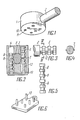
- the locking device shown contains a housing 1 (Fig. 1) z. B. has the shape of a cylinder, and a removable cylindrical latch 2. According to FIG. 2, a partially cylindrical central main space 3 (FIG. 2) and six side rooms 4 connected to it are provided in the housing 1.
- the bolt has an insertion head 5, which is introduced into the main room 3 and together with code fixers 6, which are individually arranged to be longitudinally displaceable to a limited extent in an adjacent room 4.
- code fixers 6 in the adjoining rooms 4 are moved by gravity.
- At least one longitudinal rib 7 is formed on at least one side surface of the insertion head 5, the embodiment shown having a longitudinal rib 7 on each side surface (FIG. 4).
- a code recess in the form of an annular groove 8 is implemented on each code fixer 6 (FIG. 5), the cross-sectional profile of which corresponds to that of the longitudinal rib 7.
- At least one additional annular groove 9 is implemented on each code fixer 6, the embodiment shown having four annular grooves 9.
- the width of the additional annular grooves 9 corresponds to the width or shape of the longitudinal rib 7, while the depth of this groove 9 is smaller than the height of the rib 7.
- a cover 10 is permanently attached to the housing 1, e.g. B. welded. Through holes 11 are made in the cover 10, which are connected to the associated adjoining room 4 and have a smaller cross-sectional area than the respective cross-sectional area of the adjoining rooms 4.
- the axis of each through hole 11 in the cover 10 is offset with respect to the longitudinal axis of the associated adjoining room 4.
- annular grooves 12 are incorporated on the cylindrical insertion head, which with the Code fixers 6 cooperate and their shape corresponds to the profile of the code fixers in cross section. These annular grooves 12 enable the cylindrical bolt 2 to rotate freely about the longitudinal axis in the main space 3 of the housing 1.
- the key essentially consists of a plate on which code pins 13 are fastened upright, which are inserted into the through holes 11 and interact with the associated code fixers 6 (cf. FIG. 2).
- the key can have different designs.
- a key is used to lock means of transport (such as wagons or containers), the code pins 14 of which are attached to a support element 15 in a longitudinally adjustable manner according to FIG. 7.
- Each code pin 14 has markings 16 for setting the unlocking position. This key design allows the keys to be sent when the code is transmitted separately and enables the selected unlocking code to be deleted, which makes it impossible to open the lock without permission.
- the key according to FIG. 8 can have code pins 17 which are pivotably articulated on a support element 18.
- the length of each code pin 17 corresponds to the code. This key offers ease of use and is very compact when the code pins 17 are folded.
- the key is inserted into the cover holes 11 with the code pins 13 (FIG. 6). All code fixers 6 are brought into a position according to FIG. 2, in which the code depressions 8 of all fixators 6 are located in one plane and allow the ribs 7 of the insertion head 5 to pass freely. Then the latch 2 is inserted into the housing 1 until it stops. After removal of the key, the code fixers 6 fall down due to their own weight and lock the bolt 2, whereby they are located in the annular incisions 12 of the insertion head 5. The latch 2 is released by inserting the key again.
- the code unit described can be used both in mobile and in stationary blocking devices.
- a box-shaped component (not shown) serves to limit the longitudinal displacement of the code fixers 6 in the housing 1.
- the bores for receiving the code pins 13 of the key in the housing 1 are formed at the bottom.
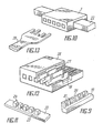
- the code recesses on the transverse in the housing 26 against the force of springs 27 movable code fixers 19 are formed as a cutout 20 and the additional recesses as blind grooves 21.
- the bolt 22 shown in FIG. 11 is rectangular and has a longitudinal rib 24 on its insertion head 23, which is subdivided by slots 25 for receiving the code fixers 19.
- the code fixers 19 are held in the rectangular housing 26 according to FIG. 12 by the springs 27 in the position shown.
- the locking device is closed and opened, as in the embodiments described above, by pulling out or inserting the code pins of a key 28 shown in FIG. 13.
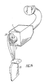
- the main room 3 is formed continuously and the insertion head 5 is pushed through the housing 1 (cf. FIG. 14).
- a transverse bore 29 is formed through which the band of a seal 30 is pulled.
- the locking device has a simple design and does not require high manufacturing accuracy.
- the code unit increases the security against locking considerably and it is practically impossible to use a lock key or duplicate key. Unauthorized opening of the locking device cannot be carried out either by successively selecting code variants or by scanning. In addition, the strength is increased and an unauthorized removal of the lock from the object to be locked with the help of heavy tools such as sledgehammers, crowbars, hacksaws and the like.
- the proposed code unit is user-friendly and requires no repair in the mobile version. Repair work on built-in locks can be carried out easily.
Landscapes
- Lock And Its Accessories (AREA)
- Surgical Instruments (AREA)
- Accommodation For Nursing Or Treatment Tables (AREA)
- Orthopedics, Nursing, And Contraception (AREA)
Applications Claiming Priority (2)
| Application Number | Priority Date | Filing Date | Title |
|---|---|---|---|
| SU884493189A RU2093653C1 (ru) | 1988-10-14 | 1988-10-14 | Блокирующее кодовое устройство |
| SU4493189 | 1988-10-14 |
Publications (2)
| Publication Number | Publication Date |
|---|---|
| EP0363957A2 true EP0363957A2 (fr) | 1990-04-18 |
| EP0363957A3 EP0363957A3 (fr) | 1991-03-27 |
Family
ID=21403769
Family Applications (1)
| Application Number | Title | Priority Date | Filing Date |
|---|---|---|---|
| EP19890118981 Withdrawn EP0363957A3 (fr) | 1988-10-14 | 1989-10-12 | Serrure mécanique |
Country Status (10)
| Country | Link |
|---|---|
| US (1) | US5024071A (fr) |
| EP (1) | EP0363957A3 (fr) |
| JP (1) | JPH02176081A (fr) |
| CN (1) | CN1041986A (fr) |
| CA (1) | CA2000624A1 (fr) |
| CS (1) | CS582889A2 (fr) |
| DK (1) | DK505789A (fr) |
| FI (1) | FI894863A7 (fr) |
| HU (1) | HU202304B (fr) |
| RU (1) | RU2093653C1 (fr) |
Families Citing this family (30)
| Publication number | Priority date | Publication date | Assignee | Title |
|---|---|---|---|---|
| US5146770A (en) * | 1991-09-27 | 1992-09-15 | Yun Sheng Chung | Card-operated lock |
| RU2135719C1 (ru) * | 1998-06-15 | 1999-08-27 | Шафиркин Давид Исаакович | Способ предотвращения несанкционированного разблокирования кодового узла устройства замкового типа |
| RU2132440C1 (ru) * | 1998-11-02 | 1999-06-27 | Шафиркин Давид Исаакович | Блокирующее кодовое устройство |
| RU2148140C1 (ru) * | 1999-03-31 | 2000-04-27 | Гладких Александр Леонидович | Запорное устройство |
| US20030074937A1 (en) * | 2000-04-04 | 2003-04-24 | Shafirkin David Isaakovich | Method for preventing unauthorized unlocking of a code unit of a device of a lock variety |
| RU2175705C1 (ru) * | 2000-04-17 | 2001-11-10 | Шафиркин Давид Исаакович | Способ предотвращения несанкционированного разблокирования кодового узла устройства замкового типа (варианты) |
| IL135972A0 (en) | 2000-05-04 | 2001-05-20 | Loktev Irina | Locking device and locks based on it |
| US6595032B2 (en) * | 2001-11-01 | 2003-07-22 | Wen-Chen Lin | Lock cylinder-free lock device |
| US7634930B2 (en) | 2002-01-03 | 2009-12-22 | Strattec Security Corporation | Lock apparatus and method |
| US6860131B2 (en) * | 2002-09-26 | 2005-03-01 | Newfrey Llc | Rekeying a lock assembly |
| US8347678B2 (en) * | 2002-09-26 | 2013-01-08 | Newfrey, Llc | Rekeyable lock cylinder assembly |
| US7114357B2 (en) | 2002-09-26 | 2006-10-03 | Newfrey, Llc | Keying system and method |
| US6862909B2 (en) * | 2002-09-26 | 2005-03-08 | Newfrey Llc | Devices, methods, and systems for keying a lock assembly |
| US6959569B2 (en) * | 2002-09-26 | 2005-11-01 | Newfrey Llc | Re-keyable lock assembly |
| CA2517887C (fr) * | 2003-03-04 | 2011-09-13 | Newfrey Llc | Ensemble cylindre de serrure permettant un changement de cle, dote de broches de longueur reglable |
| US6951123B2 (en) | 2003-03-05 | 2005-10-04 | Newfrey Llc | Rekeyable lock |
| US6973813B2 (en) * | 2003-12-05 | 2005-12-13 | Newfrey Llc | Re-keyable lock and method |
| US7007528B2 (en) | 2004-04-01 | 2006-03-07 | Newfrey Llc | Re-keyable lock cylinder |
| US20060059965A1 (en) * | 2004-09-17 | 2006-03-23 | Benstead Evan A | Rekeyable lock having 2-piece pin with rotatable member |
| US20060101880A1 (en) * | 2004-11-12 | 2006-05-18 | Ward-Dolkas Paul C | Re-keyable lock cylinder |
| US8881567B2 (en) * | 2005-10-21 | 2014-11-11 | Kwikset Corporation | Reset fixture for rekeyable lock assembly |
| RU2377376C1 (ru) * | 2008-07-16 | 2009-12-27 | Евгений Афанасьевич Колобанов | Замок с кодовым устройством |
| IL193931A (en) * | 2008-09-07 | 2012-01-31 | Mul T Lock Technologies Ltd | Movable key combination element and lock assembly |
| US8336350B2 (en) * | 2010-04-29 | 2012-12-25 | Rav Bariach (08) Industries Ltd. | Key and lock assemblies |
| US8099988B1 (en) | 2010-08-09 | 2012-01-24 | Newfrey, Llc | Tool-less rekeyable lock cylinder |
| US8291735B1 (en) | 2011-03-31 | 2012-10-23 | Newfrey, Llc | Rekeyable lock cylinder having rotatable key followers |
| CN103174331B (zh) * | 2013-03-13 | 2015-06-17 | 永康市众安锁业有限公司 | 钥匙型条式机械密码锁 |
| CN104652944B (zh) * | 2015-02-05 | 2017-02-22 | 高垚 | 一种无源多组多位密码自动顺序循环逐组变更密码锁 |
| CN113473646B (zh) * | 2017-11-21 | 2022-04-12 | 华为技术有限公司 | 一种通信方法及装置 |
| US11319726B2 (en) | 2018-10-22 | 2022-05-03 | Spectrum Brands, Inc. | Tool-less rekeyable lock cylinder |
Family Cites Families (13)
| Publication number | Priority date | Publication date | Assignee | Title |
|---|---|---|---|---|
| DD266249A (fr) * | ||||
| US690191A (en) * | 1901-08-14 | 1901-12-31 | John G Saxe | Lock. |
| US1366161A (en) * | 1919-06-17 | 1921-01-18 | Clark Francisco | Adjustable tumbler-lock |
| US1527336A (en) * | 1921-09-09 | 1925-02-24 | Verdun Muvek Reszvenytarsasag | Safety padlock |
| US2302414A (en) * | 1938-02-01 | 1942-11-17 | Buchanan-Wollaston Hugo John | Key operated mechanism |
| FR867917A (fr) * | 1940-12-04 | 1941-12-05 | Système de fermeture à pistons | |
| US2595267A (en) * | 1943-11-23 | 1952-05-06 | Julliard Maurice Etienne | Combination lock |
| US2959951A (en) * | 1958-04-16 | 1960-11-15 | Jorge J Mirkin | Safety lock |
| GB1227731A (fr) * | 1966-10-14 | 1971-04-07 | ||
| US3855826A (en) * | 1973-05-02 | 1974-12-24 | Hori Lock Kogyo Kk | Padlock |
| SU500342A1 (ru) * | 1975-01-10 | 1976-01-25 | Предприятие П/Я А-1001 | Замок с зашифрованным запирающим устройством |
| US4164857A (en) * | 1977-04-07 | 1979-08-21 | Genakis Joseph M | Plugless pin tumbler cylinder |
| US4388815A (en) * | 1980-09-08 | 1983-06-21 | Lawler Michael S | Pick-proof lock |
-
1988
- 1988-10-14 RU SU884493189A patent/RU2093653C1/ru not_active IP Right Cessation
-
1989
- 1989-10-12 HU HU895297A patent/HU202304B/hu not_active IP Right Cessation
- 1989-10-12 EP EP19890118981 patent/EP0363957A3/fr not_active Withdrawn
- 1989-10-12 DK DK505789A patent/DK505789A/da not_active Application Discontinuation
- 1989-10-13 JP JP1265289A patent/JPH02176081A/ja active Pending
- 1989-10-13 FI FI894863A patent/FI894863A7/fi not_active Application Discontinuation
- 1989-10-13 CS CS895828A patent/CS582889A2/cs unknown
- 1989-10-13 CA CA 2000624 patent/CA2000624A1/fr not_active Abandoned
- 1989-10-14 CN CN89107937A patent/CN1041986A/zh active Pending
- 1989-11-01 US US07/430,530 patent/US5024071A/en not_active Expired - Fee Related
Also Published As
| Publication number | Publication date |
|---|---|
| HUT51720A (en) | 1990-05-28 |
| JPH02176081A (ja) | 1990-07-09 |
| HU895297D0 (en) | 1990-01-28 |
| FI894863A0 (fi) | 1989-10-13 |
| DK505789D0 (da) | 1989-10-12 |
| HU202304B (en) | 1991-02-28 |
| RU2093653C1 (ru) | 1997-10-20 |
| CN1041986A (zh) | 1990-05-09 |
| US5024071A (en) | 1991-06-18 |
| CS582889A2 (en) | 1991-08-13 |
| EP0363957A3 (fr) | 1991-03-27 |
| CA2000624A1 (fr) | 1990-04-14 |
| FI894863A7 (fi) | 1990-04-15 |
| DK505789A (da) | 1990-04-15 |
Similar Documents
| Publication | Publication Date | Title |
|---|---|---|
| EP0363957A2 (fr) | Serrure mécanique | |
| DE69005060T2 (de) | Zylinderschloss und Schlüssel. | |
| EP0335069B1 (fr) | Clef plate pour serrures cylindriques ainsi que sa serrure cylindrique | |
| DE19632318A1 (de) | Verriegelungsvorrichtung für Schacht-Innendeckel | |
| DE2910886A1 (de) | Verschlussanlage | |
| DE3940393A1 (de) | Sicherheitsschloss | |
| EP3887621A1 (fr) | Système de fermeture modulaire | |
| DE3641148C2 (fr) | ||
| DE2411362C3 (de) | Verschlußvorrichtung, bestehend aus einem Drehzylinderschloß und dazugehörigem Flachschlüssel | |
| DE102007014900A1 (de) | Schließvorrichtung mit einem Schlüssel und einem Schließzylinder | |
| EP1272720A1 (fr) | Serrure a pompe comportant un boitier cylindrique et cle plate destinee a une serrure a pompe | |
| DE69003626T2 (de) | Türschutzeinrichtung. | |
| EP0620340B1 (fr) | Combinaison d'une clé plate et d'une serrure cylindrique | |
| DE4401555C2 (de) | Verriegelung für Tresor- und Wertbehältertüren | |
| AT412797B (de) | Doppelzylinderschloss | |
| DE4226269C1 (de) | Sicherheitsschloß für Wertbehälter | |
| DE4341622A1 (de) | Sicherungsvorrichtung | |
| DE3134614A1 (de) | Vorrichtung zur diebstahlsicherung von kraftfahrzeugen | |
| DE20318451U1 (de) | Zylinder für ein Sicherheitsschloß | |
| EP0942126B1 (fr) | Dispositif de verrouillage | |
| DE4235805C1 (de) | Schloß | |
| DE4230591A1 (de) | Codierbares Zylinderschloß | |
| DE4416515A1 (de) | Schließzylinder mit Abzugsschutz | |
| DE3626552A1 (de) | Zylinderschloss mit flachschluessel | |
| DE19509337A1 (de) | Kipphebel-Schliesszylinder |
Legal Events
| Date | Code | Title | Description |
|---|---|---|---|
| PUAI | Public reference made under article 153(3) epc to a published international application that has entered the european phase |
Free format text: ORIGINAL CODE: 0009012 |
|
| AK | Designated contracting states |
Kind code of ref document: A2 Designated state(s): AT DE FR GB IT |
|
| PUAL | Search report despatched |
Free format text: ORIGINAL CODE: 0009013 |
|
| AK | Designated contracting states |
Kind code of ref document: A3 Designated state(s): AT DE FR GB IT |
|
| 17P | Request for examination filed |
Effective date: 19910918 |
|
| 17Q | First examination report despatched |
Effective date: 19911106 |
|
| STAA | Information on the status of an ep patent application or granted ep patent |
Free format text: STATUS: THE APPLICATION HAS BEEN WITHDRAWN |
|
| 18W | Application withdrawn |
Withdrawal date: 19921223 |