EP0363972A2 - Bogie autodirecteur pour un véhicule ferroviaire - Google Patents
Bogie autodirecteur pour un véhicule ferroviaire Download PDFInfo
- Publication number
- EP0363972A2 EP0363972A2 EP89119006A EP89119006A EP0363972A2 EP 0363972 A2 EP0363972 A2 EP 0363972A2 EP 89119006 A EP89119006 A EP 89119006A EP 89119006 A EP89119006 A EP 89119006A EP 0363972 A2 EP0363972 A2 EP 0363972A2
- Authority
- EP
- European Patent Office
- Prior art keywords
- bogie
- fact
- fixed
- lever
- vehicle body
- Prior art date
- Legal status (The legal status is an assumption and is not a legal conclusion. Google has not performed a legal analysis and makes no representation as to the accuracy of the status listed.)
- Withdrawn
Links
Images

Classifications
-
- B—PERFORMING OPERATIONS; TRANSPORTING
- B61—RAILWAYS
- B61F—RAIL VEHICLE SUSPENSIONS, e.g. UNDERFRAMES, BOGIES OR ARRANGEMENTS OF WHEEL AXLES; RAIL VEHICLES FOR USE ON TRACKS OF DIFFERENT WIDTH; PREVENTING DERAILING OF RAIL VEHICLES; WHEEL GUARDS, OBSTRUCTION REMOVERS OR THE LIKE FOR RAIL VEHICLES
- B61F5/00—Constructional details of bogies; Connections between bogies and vehicle underframes; Arrangements or devices for adjusting or allowing self-adjustment of wheel axles or bogies when rounding curves
- B61F5/50—Other details
- B61F5/52—Bogie frames
-
- B—PERFORMING OPERATIONS; TRANSPORTING
- B61—RAILWAYS
- B61F—RAIL VEHICLE SUSPENSIONS, e.g. UNDERFRAMES, BOGIES OR ARRANGEMENTS OF WHEEL AXLES; RAIL VEHICLES FOR USE ON TRACKS OF DIFFERENT WIDTH; PREVENTING DERAILING OF RAIL VEHICLES; WHEEL GUARDS, OBSTRUCTION REMOVERS OR THE LIKE FOR RAIL VEHICLES
- B61F5/00—Constructional details of bogies; Connections between bogies and vehicle underframes; Arrangements or devices for adjusting or allowing self-adjustment of wheel axles or bogies when rounding curves
- B61F5/02—Arrangements permitting limited transverse relative movements between vehicle underframe or bolster and bogie; Connections between underframes and bogies
- B61F5/14—Side bearings
- B61F5/148—Side bearings between bolsterless bogies and underframes
-
- B—PERFORMING OPERATIONS; TRANSPORTING
- B61—RAILWAYS
- B61F—RAIL VEHICLE SUSPENSIONS, e.g. UNDERFRAMES, BOGIES OR ARRANGEMENTS OF WHEEL AXLES; RAIL VEHICLES FOR USE ON TRACKS OF DIFFERENT WIDTH; PREVENTING DERAILING OF RAIL VEHICLES; WHEEL GUARDS, OBSTRUCTION REMOVERS OR THE LIKE FOR RAIL VEHICLES
- B61F5/00—Constructional details of bogies; Connections between bogies and vehicle underframes; Arrangements or devices for adjusting or allowing self-adjustment of wheel axles or bogies when rounding curves
- B61F5/38—Arrangements or devices for adjusting or allowing self- adjustment of wheel axles or bogies when rounding curves, e.g. sliding axles, swinging axles
- B61F5/44—Adjustment controlled by movements of vehicle body
Definitions
- the present invention relates to a bogie for a railway vehicle, and in particular to a bogie having independent wheels.
- Bogies of the said type are known, which substantially comprise: a central support structure; four independent arms carrying respective axles of the wheels and articulated to the support structure by means of resilient bushes; suspension means for a body of the vehicle; and a centre casting fixed slidably to the support structure with the possibility of relative rotation with respect thereto about its vertical axis, and adapted to be rigidly fixed to the vehicle body.
- the object of the present invention is the provision of an independent wheel bogie, which will be free from the said disadvantages of known bogies.
- an independent wheel bogie for a railway vehicle comprising: a central support structure; four independent arms carrying respective axles of the wheels and articulated to the said support structure two on one side and two on an opposite side by means of respective resilient bushes having horizontal axes extending transversely with respect to the said bogie; suspension means for a body of the said vehicle; a centre casting fixed to the said support structure with the possibility of relative rotation about its vertical axis and adapted to be fixed rigidly to the said body; and a device for controlling steering of the said axles; characterised by the fact that the said control device includes at least one pair of linear actuators disposed longitudinally along the sides of the said support structure and connected at their ends to the said articulated arms on the corresponding side of the said support structure, and means for actuating the said linear actuators, activatable by a relative rotation between the said bogie and the said body.
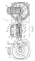
- the reference numeral 1 generally indicates a bogie for a railway vehicle.
- the bogie 1 comprises, in a manner known per se, a central support structure 2 and four arms 6 pivoted to it, two on one side and two on an opposite side thereof.
- the structure 2 has the shape of a substantially square ribbed plate provided with a rectangular central aperture 3 and formed along its front and rear edges with respective tubular supports 4 extending transversely of the bogie 1.
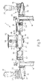
- respective shafts 5 Figure 2 opposite end portions of which project out from the supports 4, on which end portions are mounted respective arms 6 with the interposition of resilient bushes 7.
- These resilient bushes 7, which are of known type, substantially comprise a cylindrical sleeve 8 of elastomeric material vulcanised between an inner sleeve 9 and an outer metal sleeve 10, and are mounted fixedly with respect to the shafts 5 and the arms 6.
- these arms 6 are therefore substantially pivotally fixed to the structure 2 about respective horizontal axes transverse the structure 2, coincident with the axes of the shafts 5; the deformability of the sleeves 8 further allows modest rotations of the arms 6 about a vertical axis to allow self-steering as will be described hereinbelow, and about a horizontal longitudinal axis to allow possible relative movements due to a skew configuration of the rails.
- Each arm 6 includes, in particular, an attachment portion 14 provided with a transverse cylindrical seat 15 in which is housed the respective resilient bush 7, an intermediate portion 27 inclined outwardly of the bogie 1 and a longitudinal end portion 16 provided with a transverse cylindrical seat, not illustrated, in which there is mounted rigidly, projecting outwardly of the bogie, an axle 17 of a respective wheel.
- the wheels 18 are freely rotatably mounted on the respective axles 17 in a conventional manner, not illustrated, for example by means of respective pairs of taper roller bearings.
- this suspension unit 20 includes two coaxial coil springs 24, 25 mounted between resilient annular end buffers 26, and a central shock absorber 31 coaxial with the springs and visible in Figure 3, connected by ball joints to a central removable portion 32 of the support 9 and adapted to be connected by ball joints to the vehicle body.
- Respective brake discs 28 are fixed to opposite faces of the wheels 18, on which discs respective brake calipers 29 are adapted to act; these calipers 29 are mounted outside the respective arms 6 and are articulated on pins 30 projecting from the central portions 27 of the arms 6.
- the end portions 16 of the front and rear arms 6 are connected transversely together by respective anti-roll bars 34 to which are fixed two short levers 35 articulated at their opposite ends to respective suspension rods 36 linked to the vehicle body.
- the front and rear arms 6 are further connected together by tubular spacers 37 which ensure the correct gauge upon assembly and in use.
- the bogie 1 further includes a pair of shock absorbers 38 articulated to the sides of the support structure 2, which have axes inclined upwardly and outwardly of the bogie and are adapted to be connected at their upper ends to the vehicle body.
- the bogie 1 finally includes a coupling element 39 connecting it to the vehicle body, commonly known as a centre casting.
- the centre casting 39 comprises, in a known way, a prismatic slide block slidably housed within the aperture 3 of the support structure 2 and free to perform with respect to it limited relative translations in a longitudinal sense and translations of relatively greater amplitude in a transverse sense.
- On the slide block 40 are fixed two resilient lateral buffers 44 serving to absorb the impacts between the slide block 40 and the lateral edges of the aperture 3.
- Within a vertical cylindrical seat passing through the slide bar 40 is housed a pin 45 on the ends of which are mounted two discs 46 clamped against the slide block 40 and cooperating with opposite faces of the support structure 2 with the interposition of respective resilient elements 47 ( Figures 2 and 3).
- the bogie 1 includes a steering control device generally indicated 50.
- the device 50 substantially comprises a pair of linear actuators indicated 54 disposed longitudinally along the sides of the support structure 2 and connecting together the attachment portions 14 of the pair of arms 6 of the respective side of the bogie 1.
- these actuators 54 include a cylindrical nut 55 having an internal right hand thread over half its length and a left hand thread for the other half of its length, and a pair of screws 56, respectively right hand and left hand threads, engaging the corresponding threaded portions of the nut 55 and connected at their free ends with respective support brackets 57 projecting outwardly from the attachment portions 14 of the arms 6.
- the connection between the screws 56 and the brackets 57 is made by means of ball joints 67 including respective resiliently deformable bushes 68 ( Figure 1).
- the device 50 further includes a shaft 58 (Figure 2) housed diametrically in a longitudinal direction within the cylindrical body 48 and supported close to its ends, which project from the cylindrical body 48, by means of a pair of bushes 59 housed in respective holes 60 of the body 48.
- a shaft 58 ( Figure 2) housed diametrically in a longitudinal direction within the cylindrical body 48 and supported close to its ends, which project from the cylindrical body 48, by means of a pair of bushes 59 housed in respective holes 60 of the body 48.
- the shaft 58 are rigidly fixed, for example by means of conical tangential pins not illustrated, the upper ends of two vertical levers 64 to the lower ends of which are articulated respective substantially horizontal struts 65 facing opposite sides of the bogie.
- These struts 65 are articulated at their outer ends to respective substantially L-shape levers 66 and welded at their opposite ends to respective nuts 55.
- the relative lateral translation motion again has no uninfluence on the steering: in fact, it causes a substantially concordant inclination of the levers 64 about their pivots which fix them to the struts 65 and the consequent rotation of the shaft 58 about its axis without any action on the actuators 54.
- the relative rotation between the vehicle body and the bogie 1 is converted into a rotation of the shaft 58, carried by the cylindrical body 48 fixed to the vehicle body itself, about the vertical axis of the centre casting 39.
- This rotation causes on the levers 64 two thrusts in transverse directions of opposite senses; these thrusts are transmitted from the levers 64 to the struts 65 and cause a translation in an axial sense which is converted into a rotation of the respective levers 66 and consequently of the nuts 55 about their axes.
- These opposite and equal rotations correspond to equal and opposite translations of the screws 56 and, therefore, cause an approaching motion between the arms 6 of one side and a separation between the arms 6 of the other side, allowed by the deformability of the resilient bushes 7.
- the arms 6 rotate substantially about the pivot defined by the resilient bushes 7; the axles 17 fixed to the arms 6 consequently turn.
- the sense of the thread of the screws 56 is chosen in such a way that the device 50 causes a separation of the arms 6 which are on the outside of the curve and an approach of the arms 6 on the inside. More particularly, if the bogie 1 is the rear bogie of a vehicle when the direction of movement of the vehicle itself is that indicated with the arrow in Figure 1, the screws 56 fixed to the rear arms 6 of the bogie (to the left in Figures 1 and 2) are right hand threads, whilst those fixed to the front arms (the right in Figures 1 and 2) are left hand threads. The senses of the threads must be reversed if the bogie 1 is the rear bogie since the relative rotation with respect to the vehicle body will be opposite.
- the pitch of the screws 56 is chosen in such a way that the angle of rotation of the arms 6 is such as to move the axles so as to lie in a perfectly radial direction with respect to the rails.
- the required rotation is about 0.0036 rad.
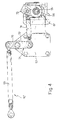
- each strut 65 is fixed at one end to a respective lever 54 (not illustrated in Figure 4) and at its opposite end to an upper arm 70 of a lever 71 pivoted to the bracket 57 and disposed at rest in a substantially orthogonal direction with respect to the strut 65 itself.
- a lower arm 72 of the lever 71 is connected by means of a further strut 74 to a fork lever 73 welded onto the nut 55.
- the device 50 ensures the correct steering of the axles, disposing them in a radial direction with respect to the curve of the track. This significantly reduces the wear of the wheels and the rails.
- the forces transmitted by the linear actuators 54 to the arms 6 are of a relatively low intensity thanks to the deformability of the elastomeric material sleeves 8 of the resilient bushes 7 and to the large leverage which these forces have with respect to the points of articulation of the arms 6.
- the resilient bushes 68 of the ball joints 67 which connect the screws 56 to the brackets 57 permit possible relative motions between the arms of each side, and in particular skew dispositions of the axles due to irregularities in the rails.
- the resilient sleeves 8 and the resilient bushes 68 are parallel to one another and consequently the overall rigidity of the fixing of the arms 6 to the support structure 2 is greater than if the stresses on the arms were imposed by the device 50 (or 50′).
- the bogie 1 can have modifications and variations introduced thereto which do not depart from the protective ambit of the present invention.
- the screw and nut actuators 54 can be replaced by fluid pressure actuators controlled by respective valves operated by means for detecting the relative angle between the vehicle body and the bogie, for example lever mechanisms insensitive to relative translations between them, or by electrical actuators operated by similar means.
Landscapes
- Engineering & Computer Science (AREA)
- Mechanical Engineering (AREA)
- Vehicle Body Suspensions (AREA)
- Platform Screen Doors And Railroad Systems (AREA)
Applications Claiming Priority (2)
| Application Number | Priority Date | Filing Date | Title |
|---|---|---|---|
| IT67921/88A IT1224491B (it) | 1988-10-14 | 1988-10-14 | Carrello autosterzante per un veicolo ferroviario |
| IT6792188 | 1988-10-14 |
Publications (2)
| Publication Number | Publication Date |
|---|---|
| EP0363972A2 true EP0363972A2 (fr) | 1990-04-18 |
| EP0363972A3 EP0363972A3 (fr) | 1990-07-18 |
Family
ID=11306387
Family Applications (1)
| Application Number | Title | Priority Date | Filing Date |
|---|---|---|---|
| EP89119006A Withdrawn EP0363972A3 (fr) | 1988-10-14 | 1989-10-12 | Bogie autodirecteur pour un véhicule ferroviaire |
Country Status (4)
| Country | Link |
|---|---|
| US (1) | US5024165A (fr) |
| EP (1) | EP0363972A3 (fr) |
| JP (1) | JPH03563A (fr) |
| IT (1) | IT1224491B (fr) |
Cited By (1)
| Publication number | Priority date | Publication date | Assignee | Title |
|---|---|---|---|---|
| TWI477413B (zh) * | 2011-07-21 | 2015-03-21 | Nippon Steel & Sumitomo Metal Corp | Rail vehicles for steering vehicles |
Families Citing this family (14)
| Publication number | Priority date | Publication date | Assignee | Title |
|---|---|---|---|---|
| US5918546A (en) * | 1995-11-20 | 1999-07-06 | Transportation Investors Service Corporation | Linear steering truck |
| US5666885A (en) * | 1995-11-20 | 1997-09-16 | Transportation Investors Service Corporation | Linear steering truck |
| US6048015A (en) * | 1998-01-08 | 2000-04-11 | T.W. Blasingame Company, Inc. | Differential action railroad car wheelset |
| DE69908369T2 (de) * | 1998-08-06 | 2004-02-19 | Scheffel, Herbert, Pretoria | Vorrichtung zur dämpfung von schubwirkungen zwischen den achsen eines selbstlenkenden drehgestells sowie selbstlenkendes drehgestell mit einer derartigen vorrichtung |
| US7096795B2 (en) * | 2003-05-06 | 2006-08-29 | Active Steering, Llc | Linear steering truck |
| US7858544B2 (en) * | 2004-09-10 | 2010-12-28 | First Quality Nonwovens, Inc. | Hydroengorged spunmelt nonwovens |
| US7624687B2 (en) * | 2006-10-26 | 2009-12-01 | Sharma & Associates, Inc. | Truck apparatus for railway cars |
| KR100921549B1 (ko) | 2007-12-06 | 2009-10-12 | 한국철도기술연구원 | 철도차량용 능동 조향대차 |
| ITTO20110672A1 (it) | 2011-07-25 | 2013-01-26 | Ansaldobreda Spa | Carrello sterzante, in particolare per una carrozza di tram |
| AT514373B1 (de) * | 2013-05-02 | 2019-03-15 | Siemens Ag Oesterreich | Radsatzlagerung für den Radsatz eines Schienenfahrzeugs mit innengelagertem Drehgestell |
| CN104002829B (zh) * | 2014-05-22 | 2016-09-21 | 武汉理工大学 | 列车能量回馈式主动径向转向架 |
| RU200957U1 (ru) * | 2020-07-22 | 2020-11-20 | Общество с ограниченной ответственностью "ПетроРемСтрой" (ООО "ПРС") | Тяга торсионного стабилизатора поперечной устойчивости кузова транспортного средства |
| CN111845789B (zh) * | 2020-08-31 | 2025-07-18 | 西南交通大学 | 适合于单轨悬吊车辆的转向架悬吊梁 |
| CN119636837B (zh) * | 2025-01-24 | 2025-06-17 | 长春速建新技术开发有限公司 | 一种径向转向架的多功能转向控制系统 |
Family Cites Families (10)
| Publication number | Priority date | Publication date | Assignee | Title |
|---|---|---|---|---|
| US2641499A (en) * | 1947-03-07 | 1953-06-09 | American Car & Foundry Co | Axle construction |
| DE837711C (de) * | 1949-02-10 | 1952-05-02 | Roman Liechty Dipl Ing | Achssteuereinrichtung fuer die Radachsen von Schienenfahrzeugen mit einem dreiarmigen Verstellhebel |
| DE850623C (de) * | 1951-03-10 | 1952-09-25 | Linke Hofmann Busch | Drehgestell fuer Schienenfahrzeuge mit radialer Achseinstellung |
| DE917308C (de) * | 1951-03-10 | 1954-08-30 | Linke Hofmann Busch | Drehgestell fuer Schienenfahrzeuge mit selbsttaetiger radialer Achseinstellung |
| US2746398A (en) * | 1954-02-04 | 1956-05-22 | Talgo Patentes | Axle steering mechanism for railway vehicles |
| US3974779A (en) * | 1974-10-31 | 1976-08-17 | Automatisk Doseringskompensator Ab | Vehicle bogie |
| CA1115126A (fr) * | 1978-07-12 | 1981-12-29 | Urban Transportation Development Corporation Ltd. | Bogie orientable a roue unique pour vehicule articule de chemin de fer |
| FR2530567A1 (fr) * | 1982-07-26 | 1984-01-27 | Anf Ind | Bogie a essieux orientables pour vehicules ferroviaires |
| DE3331559A1 (de) * | 1983-09-01 | 1985-03-28 | Thyssen Industrie Ag, 4300 Essen | Achssteuerung fuer schienenfahrzeuge |
| IT1182317B (it) * | 1984-10-05 | 1987-10-05 | Fiat Ferroviaria Savigliano | Carrello per veicoli ferroviari a ruote indipendenti |
-
1988
- 1988-10-14 IT IT67921/88A patent/IT1224491B/it active
-
1989
- 1989-10-11 US US07/419,675 patent/US5024165A/en not_active Expired - Fee Related
- 1989-10-12 EP EP89119006A patent/EP0363972A3/fr not_active Withdrawn
- 1989-10-13 JP JP1265290A patent/JPH03563A/ja active Pending
Cited By (1)
| Publication number | Priority date | Publication date | Assignee | Title |
|---|---|---|---|---|
| TWI477413B (zh) * | 2011-07-21 | 2015-03-21 | Nippon Steel & Sumitomo Metal Corp | Rail vehicles for steering vehicles |
Also Published As
| Publication number | Publication date |
|---|---|
| US5024165A (en) | 1991-06-18 |
| JPH03563A (ja) | 1991-01-07 |
| IT8867921A0 (it) | 1988-10-14 |
| IT1224491B (it) | 1990-10-04 |
| EP0363972A3 (fr) | 1990-07-18 |
Similar Documents
| Publication | Publication Date | Title |
|---|---|---|
| US5024165A (en) | Self-steering bogie for a railway vehicle | |
| US3528374A (en) | Railway truck resiliently interconnected axle boxes | |
| US2226406A (en) | Vehicle wheel mounting | |
| US2706113A (en) | Spring suspension for vehicles | |
| US4974872A (en) | Axle suspension with two air springs supporting a telescopic strut | |
| JP7143011B2 (ja) | 車両用インホイール3アームサスペンション | |
| US2756067A (en) | Independent wheel suspensions for power driven vehicles | |
| JPS6357307A (ja) | ダブルリンク式サスペンシヨン装置 | |
| US4429900A (en) | Automotive suspension system for maintaining the rear wheels substantially parallel to one another throughout use | |
| JPS62253589A (ja) | 2輪車用の懸架・操舵装置 | |
| EP0494393A1 (fr) | Suspension de roue indépendante | |
| EP1615788B1 (fr) | Suspension de roue pour vehicules | |
| CS236859B2 (en) | Suspension for coupled axles | |
| JPH0518724B2 (fr) | ||
| US3674285A (en) | Vehicle suspension | |
| US2253042A (en) | Truck suspension means | |
| US4614358A (en) | Stabilizer for vehicles | |
| CN112955373B (zh) | 摩托车的翻转解耦的转向装置以及摩托车 | |
| US3099458A (en) | Vehicle suspension system | |
| US2402562A (en) | Independently sprung axle construction | |
| US2233145A (en) | Spring suspension | |
| US5992866A (en) | Motor-vehicle rear suspension | |
| US3361442A (en) | Tandem wheel suspension | |
| US2153862A (en) | Steering means | |
| US2112293A (en) | Individual wheel spring suspension |
Legal Events
| Date | Code | Title | Description |
|---|---|---|---|
| PUAI | Public reference made under article 153(3) epc to a published international application that has entered the european phase |
Free format text: ORIGINAL CODE: 0009012 |
|
| AK | Designated contracting states |
Kind code of ref document: A2 Designated state(s): AT BE CH DE ES FR GB GR LI LU NL SE |
|
| PUAL | Search report despatched |
Free format text: ORIGINAL CODE: 0009013 |
|
| AK | Designated contracting states |
Kind code of ref document: A3 Designated state(s): AT BE CH DE ES FR GB GR LI LU NL SE |
|
| STAA | Information on the status of an ep patent application or granted ep patent |
Free format text: STATUS: THE APPLICATION IS DEEMED TO BE WITHDRAWN |
|
| 18D | Application deemed to be withdrawn |
Effective date: 19910119 |