EP0364002A2 - Tracteur - Google Patents
Tracteur Download PDFInfo
- Publication number
- EP0364002A2 EP0364002A2 EP89122064A EP89122064A EP0364002A2 EP 0364002 A2 EP0364002 A2 EP 0364002A2 EP 89122064 A EP89122064 A EP 89122064A EP 89122064 A EP89122064 A EP 89122064A EP 0364002 A2 EP0364002 A2 EP 0364002A2
- Authority
- EP
- European Patent Office
- Prior art keywords
- tractor
- front wheels
- wheels
- engine
- approximately
- Prior art date
- Legal status (The legal status is an assumption and is not a legal conclusion. Google has not performed a legal analysis and makes no representation as to the accuracy of the status listed.)
- Withdrawn
Links
Images



Classifications
-
- B—PERFORMING OPERATIONS; TRANSPORTING
- B62—LAND VEHICLES FOR TRAVELLING OTHERWISE THAN ON RAILS
- B62D—MOTOR VEHICLES; TRAILERS
- B62D49/00—Tractors
- B62D49/02—Tractors modified to take lifting devices
-
- B—PERFORMING OPERATIONS; TRANSPORTING
- B60—VEHICLES IN GENERAL
- B60K—ARRANGEMENT OR MOUNTING OF PROPULSION UNITS OR OF TRANSMISSIONS IN VEHICLES; ARRANGEMENT OR MOUNTING OF PLURAL DIVERSE PRIME-MOVERS IN VEHICLES; AUXILIARY DRIVES FOR VEHICLES; INSTRUMENTATION OR DASHBOARDS FOR VEHICLES; ARRANGEMENTS IN CONNECTION WITH COOLING, AIR INTAKE, GAS EXHAUST OR FUEL SUPPLY OF PROPULSION UNITS IN VEHICLES
- B60K5/00—Arrangement or mounting of internal-combustion or jet-propulsion units
- B60K5/08—Arrangement or mounting of internal-combustion or jet-propulsion units comprising more than one engine
-
- B—PERFORMING OPERATIONS; TRANSPORTING
- B62—LAND VEHICLES FOR TRAVELLING OTHERWISE THAN ON RAILS
- B62D—MOTOR VEHICLES; TRAILERS
- B62D49/00—Tractors
- B62D49/06—Tractors adapted for multi-purpose use
- B62D49/0678—Tractors of variable track width or wheel base
-
- B—PERFORMING OPERATIONS; TRANSPORTING
- B62—LAND VEHICLES FOR TRAVELLING OTHERWISE THAN ON RAILS
- B62D—MOTOR VEHICLES; TRAILERS
- B62D7/00—Steering linkage; Stub axles or their mountings
- B62D7/02—Steering linkage; Stub axles or their mountings for pivoted bogies
Definitions
- the invention relates to a tractor, more specifically an agricultural tractor, having at least one engine for driving one or more wheels of the tractor, at least one lifting device for coupling implements to the tractor, as well as at least one power take-off shaft.
- tractors of this type have the disadvantage that they are not always suitable to efficiently perform important operations such as preparing and sowing fields.
- a normal commercially available tractor which requires a high-power engine for performing all common operations, including for example ploughing, is too heavy.
- a tractor does not require a great power relative to its total performance. Because of its great weight, the known, standard tractor spoils the soil structure, as a result of which plants develop to a less satisfactory extent and the yield becomes unsatisfactory.
- the front wheels of the tractor are hingeably mounted to the tractor frame in such a way that the distance between the front wheels will be changeable.
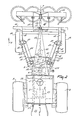
- a frame 1 of the tractor shown in the Figures 1 - 5 is constituted by the housings of a differential and rear axle housing 2 of a gear box 3 fitted to the front thereof, and of a first drive engine 4 fastened to the front of said gear box, all this seen in the direction of travel A.
- the frame portions 2 to 4 are preferably constituted by standard production parts of large-scale produced tractors of the middle class having a capacity of, for example, approximately 70 kW. These standard parts have the advantage that their prices are comparatively low as these parts are produced in large quantities and moreover are comparatively light, as said parts need generate, or convey, only a comparatively low power.
- a radial bearing by means of which a beam 6 is supported capable of swivelling around a horizontal swivel axle 8 located in the vertical longitudinal symmetry plane 7 ( Figure 2) of the tractor, is fitted to the front of the engine 4.
- the beam 6 extends transversely of the direction of travel A and, if the tractor stands on a flat plane, is in a horizontal direction.
- the beam 6 is constituted by a hollow cylindrical beam, is arranged symmetrically relative to the symmetry plane 7 and extends to approximately the plane defining the inner sides of the rear wheels fitted to the rear axle housing 2.
- the front part of the tractor is fastened to the beam 6, this part consequently being capable of swivelling around the swivel axle 8 relative to the frame 1 associated with the rearmost portion.
- a portal structure which, in a side elevational view, is approximately in the shape of an arc, is rigidly fastened at each of the two ends of the beam 6; the two portal structures 10 are of a symmetrical construction relative to the symmetry plane 7.
- a hollow beam section 11 of the portal structure 10 extends obliquely in a forward, an upward and also an outward direction, which beam - seen in the forward direction - passes into a hollow cylindrical beam 12 which is directed approximately horizontally and in parallel with the symmetry plane 7, the beam 12 passing into a hollow cylindrical beam section 13 which is likewise directed in parallel with the symmetry plane 7 and inclines downwards from the beam 12.
- the whole of the portal structure 10 is located outside the circumference of front wheels 14, still further to be described, and curves around the circumference of the upper portion of the front wheels 14.
- the two beams 13 of the structure 10 are rigidly interconnected by means of a hollow cross-beam 15, which is arranged parallel to the beam 6.
- lower connecting points 16 and near the symmetry plane 7 an upper connecting point 17 for two lower lifting arms 18 and an upper arm 19 of a front three-point lifting device 20 are provided on the cross-beam 15.
- the beams 12 and 13 are disposed near the vertical symmetry plane of the rear wheel 9 located at the same side of the plane 7.
- the beams 11 of the structure 10 are arranged such relative to the direction of travel A that they are mutually divergent (Figure 2).
- each pair of pipes 21 and 22 points upwards and approximately vertically.
- Each individual pipe 21 and 22 is arranged capable of swivelling relative to the other pipe and also relative to the pair of bearings 21.
- the pipes 21 and 22 are disposed near the front of the beam 6 and near the inside of the beam 11 of the portal structure 10.
- the inner pipe has its bottom side and also its top side projecting from the top and bottom sides, respectively, of the outer pipe.
- each beam 25 supports one of the front wheels 14 preceding it at some distance.
- each beam 25 is rigidly fastened to one of the pipes 22 and the latter is capable of rotation with the beam 6 around the swivel axle 8, the two front wheels are freely swivable around the swivel axle 8 relative to the frame 1 of the rear portion of the tractor.
- each supporting beam 25 has a bush 26 in which an upwardly directed wheel carrier 27 is disposed, capable of swivelling, around an upwardly directed shaft.
- each wheel carrier 27 supports a hydraulic engine which is capable of driving the relevant front wheel 14.
- Each supporting beam 25, together with the associated front wheel 14, is consequently capable of rotation around the centre line 24, relative to the beam 6 and the frame 1, since the pipe 22 is capable of swivelling around the centre line 24 relative to these parts.
- the bottom of each supporting beam 25 is present at least in the region of the bottom side of the beam 12 of the portal structure 10, so that in the event of steering wheel movement the front wheels 14 are not obstructed by these parts.
- Each of the two pipes located on either side of the symmetry plane 7 has at its front and its bottom a lug 29 which extends forwards in the horizontal direction.
- the foremost ends of the lugs 29 are interconnected capable of swivelling via a hydraulic cylinder 30, which is operable from the driver's seat in the tractor.
- the hydraulic cylinder 30 extends horizontally and approximately perpendicularly to the symmetry plane 7 ( Figures 2, 3 and 5).
- one of the two pipes 22 is provided with a lug 31 located in the extension of the lug 29 belonging to that pipe, but extends from the pipe 29 in the opposite direction, so to the rear.
- the rearmost end of the lug 31 has a swivel axle 32.
- the pipe 22 located at the other side of the symmetry plane 7 is not provided with such a lug 31.
- a swivel axle 33 is disposed at a short distance behind the swivable connection of the hydraulic cylinder 30 ( Figure 4).
- the spacing between the swivel axle 33 and the centre line 24 of the associated pipe 22 is equal to the spacing between the swivel axle 32 and the swivel axle 24 of the pipe 22 located at the other side of the symmetry plane 7.
- the lug 29 in which the swivel axle 33 is disposed and the lug 31 in which the swivel axle 32 is disposed are coupled to each other by means of a coupling rod 34 coupling the motions of the two pipes 22. As shown in Figure 4 or Figure 5, the centre line of the coupling rod 34 intersects the plane enclosing the two centre lines 24.
- a horizontally, outwardly extending lug 35 is fastened to the top of each of the two wheel carriers 27, while a lug 36 of the same dimensions and extending in the same direction as the lug 35 is fastened to that end of each pipe 21 projecting above the pipe 22.
- the ends of the two lugs 35 and 36 are each provided with upward swivel axles 37 and 38, respectively, which are coupled by a coupling rod 39. Seen in the view shown in Figure 5, the swivel axles 37 and 38, the centre line 24 of the pipe 21 and the centre line of the wheel carrier 27 form the vertices of a parallelogram, so that in swivelling of pipe 21 through a certain angle the wheel carrier 27 and the associated wheel 14 swivel through the same angle.
- a lug 39 which extends to the front and whose end is provided with a vertical swivel axle 40 is fitted to the bottom end of each pipe 21.
- the structure, dimensions and directions of the lugs 39 are indentical.
- the two swivel axles 40 are intercoupled by means of a rod 41, which is directed horizontally and approximately perpendicularly to the symmetry plane 7.
- the two swivel axles 40 and the two centre lines 24 form the vertices of a swivable parallelogram construction.
- Each lug 36 is provided with a swivel axle 42 located between the pipe 21 and the associated swivel axle 38.
- the approximately vertical swivel axle 42 has for its object to bearing-support the free end of the piston rod of a hydraulic cylinder 43A ( Figure 2), the cylinder of which itself is fitted capable of swivelling by means of a ball joint, relative to the frame 1. If the cylinder 43 is operated from the driver's seat, the lugs 36 and 35 and also the associated wheel 14 will be swivelled through a certain angle, while the lug 36 and 35 and the associated wheel 14, located at the other side of the symmetry plane 7, will be coupled such, by means of the rod 41 that the two front wheels 14 have the same steering wheel movement.
- the front wheels 14 are capable of swiveling around the centre lines of the associated wheel carriers 27 through an angle of approximately 65° to both one side and the other side (so through a total angle of approximately 130°), from the appropriate position for driving straight. Then a position of the front wheels can be obtained in which the centre lines of the front wheels, in plan view, intersect a point at one side of the tractor located near the outer side of one of the rear wheels 9.
- the tractor it is consequently possible for the tractor to be rotated entirely around said last swivel point; if this is effected at the end of a tilled strip of field, it is possible, after the tractor has been turned around, to achieve that the tractor is in the appropriate position for tilling the field strip contiguous to the tilled strip of field, without the need for manoeuvring on the head-end of the field. This is particularly important for preparing a seed bed and sowing the field.
- the tractor includes a second drive engine 43, whose crank shaft, which extends approximately in the direction of travel A, is located approximately in the symmetry plane 7.
- the engine 43 - as will be apparent from Figure 1 and considered in the direction of travel A - is arranged at least predominantly in front of and at angle above the first drive engine 4, near the front portion of the tractor and behind the front axis determined by the rotary axis of the front wheels 14.
- the second drive engine 43 also has a power of approximately 70 kW and may be of a structure identical to the engine 4 and be of the same production series.
- the engine 43 can be fastened to the frame 1, but it is alternatively possible for the engine 43 to be fastened to the front portion of the tractor, which is swivable relative to the frame 1 around the swivel axle 8.
- a reduction gear box 44 which comprises a clutch operable by the driver, is fitted to the front of the engine 43.
- a hydraulic pump 45 drivable by this engine and being hydraulically coupled to the hydraulic engines 28 of the front wheels 14. This hydraulic coupling to the front wheels can be of a construction which allows its switch-on and switch-off from the driver's seat.
- the reduction gear box 44 has an outgoing shaft to which a forwardly-extending drive axle 46 is coupled, whose foremost end is in drivable connection, by means of a possibly changeable gear box 47, with a front power take-off shaft 48 of the tractor which, by means of an intermediate shaft 49 is capable of driving an agricultural machine 50 coupled to the foremost lifting device 20, with a speed of rotation of approximately 540 and/or 1000 revs/minute and which is supported by the frame 1 of the tractor by means of the gear box 47.
- the power take-off shaft drive 44, 46, 47, 48 is - as can be seen from Figure 1 - located substantially above the lowermost boundary of the portal structure 10, so that the swivability of the front wheels 14 is not impeded.
- the second drive engine 43 is provided with a clutch 51 directly attached to the frame 1, which clutch, via a possibly changeable reduction gear box 52, can drive a rear power take-off shaft 53 mounted relative to the housing 2 of the frame 1 with a speed of rotation of approximately 540 and/or 1000 revs/minute.
- the gear box 52 extends from the outgoing shaft of the second engine 43 at a downward angle and outwardly, so that the power take-off shaft 53 is passed along one of the sides of the frame 1. Consequently, the power take-off shaft 53 is located at one side and remote from the symmetry plane 7.
- the clutch 51 as also the clutch 44, is operable from the driver's seat.
- the tractor has a second rear power take-off shaft 54, which is located in the symmetry plane 7 and is drivable by the first engine 4 via a clutch 55A which is also operable from the driver's seat.
- the rear power take-off shaft 54 forms part of the standard components 2, 3, 4 such as they are mass-produced for a commercially available tractor. The latter also applies to a rear three-point lifting device 55 of the tractor.
- the two engines are arranged approximately symmetrically relative to the symmetry plane 7.
- the rear wheels 9 are driven by the first drive engine 4 in a manner customary for normal, middle-class commercial tractors, the drive torque being applied by means of the gear box 3 to be operated by the driver, to the differential and the rear axle housing 2.
- the second drive engine 43 which, as also the first drive engine 4, has a power of, for example, approximately 70 kW and in principle may be of an identical structure (although this is not imperative), drives during operation the rear power take-off shaft 53 via the clutch 51 and the gear wheel transmission 52, and by means of the gear wheel transmission and clutch 44 drives the shaft 46, the gear box 47 and the front power take-off shaft 48.
- the second drive engine 43 can also drive the hydraulic pump 45 which - if so desired - can drive the hydraulic engines 28 and consequently the front wheels 14 via a hydraulic connection, not shown.
- This last-mentioned drive of the front wheels 14 is, however, not necessary in all circumstances.
- the hydraulic pump 45 has an adjustable yield, which can be set from the driver's seat. If it is no longer necessary to drive the front wheels 14, the pump 45 can be set to "0" yield, as a result of which the entire power of the second drive engine 43 becomes available for driving the rear power take-off shaft 53 and the front power take-off shaft 48.
- the innermost position of the front wheels 14 with the narrowest track width has, as mentioned already in the foregoing, significance for preserving the soil structure during sowing or preparing of the seed bed. This combines with the comparatively light weight of the tractor, as then the pressure per non-recurrently driven wheel mark is as low as possible.
- the front wheels together are capable of free swivelling relative to the frame 1 around the centre line, it is achieved in all circumstances that both front wheels bear on the soil with the same pressure, so that in the case of an uneven field, the soil in the wheel mark of the front wheels is prevented from being locally depressed with a force which might possibly increase to twice this force if the wheels were rigidly fastened relative to the frame 1.
- the two front wheels 14 are swivelled to the same extent around the centre line of the associated wheel carriers 27 because of the presence of the rod 41, which couples the wheel rotation. Because of the afore-mentioned large wheel movement of not more than approximately 130°, the tractor can be rotated around a point located near the outer side of one of the tractor wheels. Because of the steering structure in the form of a parallelogram of the front wheels 14, it is accomplished that the position of the front wheels during a change of their track width remains the same for a blocked hydraulic cylinder 43A. Vice versa, steering the front wheels 14 does not improve the track width of these wheels in the event of a blocked hydraulic cylinder 30.
- the driver further has a driver's cabin 56, which - seen in the side elevational view of Figure 1 - is predominantly mounted over the rear wheels 9, so that the driver, who is seated in a driver's seat 57, has a good view of the implements fastened to the lifting device 55 and also of the implements fastened to the front lifting device 20. Also the setting of the track width of the front wheels 14 can be judged from the driver's seat 57, as the symmetrically arranged second engine 43 does not impede a proper view of this engine (cf. Figure 2).
- the track width is adjustable from approximately 230 cms to approximately 75 cms.
- the rear wheels 9 have a diameter of approximately 160 cms and a width of approximately 60 cms, whilst in this embodiment the front wheels 14 have a diameter of approximately 120 cms and a width of approximately 40 to 60 cms.
Landscapes
- Engineering & Computer Science (AREA)
- Chemical & Material Sciences (AREA)
- Combustion & Propulsion (AREA)
- Transportation (AREA)
- Mechanical Engineering (AREA)
- Agricultural Machines (AREA)
Priority Applications (1)
| Application Number | Priority Date | Filing Date | Title |
|---|---|---|---|
| EP89122064A EP0364002A3 (fr) | 1984-11-15 | 1985-11-14 | Tracteur |
Applications Claiming Priority (3)
| Application Number | Priority Date | Filing Date | Title |
|---|---|---|---|
| NL8403484A NL8403484A (nl) | 1984-11-15 | 1984-11-15 | Trekker. |
| NL8403484 | 1984-11-15 | ||
| EP89122064A EP0364002A3 (fr) | 1984-11-15 | 1985-11-14 | Tracteur |
Related Parent Applications (2)
| Application Number | Title | Priority Date | Filing Date |
|---|---|---|---|
| EP85201876.1 Division | 1985-11-14 | ||
| EP19850201876 Division EP0182437B1 (fr) | 1984-11-15 | 1985-11-14 | Tracteur |
Publications (2)
| Publication Number | Publication Date |
|---|---|
| EP0364002A2 true EP0364002A2 (fr) | 1990-04-18 |
| EP0364002A3 EP0364002A3 (fr) | 1990-06-06 |
Family
ID=26120801
Family Applications (1)
| Application Number | Title | Priority Date | Filing Date |
|---|---|---|---|
| EP89122064A Withdrawn EP0364002A3 (fr) | 1984-11-15 | 1985-11-14 | Tracteur |
Country Status (1)
| Country | Link |
|---|---|
| EP (1) | EP0364002A3 (fr) |
Cited By (4)
| Publication number | Priority date | Publication date | Assignee | Title |
|---|---|---|---|---|
| NL1002535C2 (nl) * | 1996-03-05 | 1997-09-08 | Schuitemaker Mach Bv | Trekker-aanhangwagencombinatie voor agrarisch gebruik en aanhangwagen voor toepassing in de combinatie. |
| US6902022B2 (en) | 2002-06-13 | 2005-06-07 | Society For Research And Initiatives (Sristi) | Tractor having a convertible front end and variable track width and related methods |
| WO2005056308A1 (fr) * | 2003-12-11 | 2005-06-23 | Singapore Technologies Kinetics Ltd | Systeme de reglage de voie |
| WO2012084827A1 (fr) * | 2010-12-21 | 2012-06-28 | Valtra Oy Ab | Essieux de véhicule à voie variable |
Family Cites Families (5)
| Publication number | Priority date | Publication date | Assignee | Title |
|---|---|---|---|---|
| AT209724B (de) * | 1959-04-07 | 1960-06-25 | Traktorenwerk Schoenebeck Veb | Teleskopartig verschiebbare Vorderachsen von Kraftfahrzeugen |
| US3899037A (en) * | 1973-07-16 | 1975-08-12 | Paul A Yuker | Chassis apparatus for all terrain vehicles |
| FR2265600A1 (en) * | 1974-03-28 | 1975-10-24 | Lhospitalier Jean Noel | Self-propelled crop cutting vehicle - has chassis supported on steering and driving wheel gantries with adjustable tracks |
| US4109747A (en) * | 1976-05-13 | 1978-08-29 | American Hoist & Derrick Company | Steering mechanism |
| NL8204359A (nl) * | 1982-11-11 | 1984-06-01 | Lely Nv C Van Der | Trekker, in het bijzonder voor landbouwdoeleinden. |
-
1985
- 1985-11-14 EP EP89122064A patent/EP0364002A3/fr not_active Withdrawn
Cited By (5)
| Publication number | Priority date | Publication date | Assignee | Title |
|---|---|---|---|---|
| NL1002535C2 (nl) * | 1996-03-05 | 1997-09-08 | Schuitemaker Mach Bv | Trekker-aanhangwagencombinatie voor agrarisch gebruik en aanhangwagen voor toepassing in de combinatie. |
| US6902022B2 (en) | 2002-06-13 | 2005-06-07 | Society For Research And Initiatives (Sristi) | Tractor having a convertible front end and variable track width and related methods |
| WO2005056308A1 (fr) * | 2003-12-11 | 2005-06-23 | Singapore Technologies Kinetics Ltd | Systeme de reglage de voie |
| WO2012084827A1 (fr) * | 2010-12-21 | 2012-06-28 | Valtra Oy Ab | Essieux de véhicule à voie variable |
| US9266394B2 (en) | 2010-12-21 | 2016-02-23 | Valtra Oy Ab | Vehicle axles with variable track width |
Also Published As
| Publication number | Publication date |
|---|---|
| EP0364002A3 (fr) | 1990-06-06 |
Similar Documents
| Publication | Publication Date | Title |
|---|---|---|
| US5335739A (en) | Agricultural vehicle | |
| US4564073A (en) | Plow or harrow | |
| US4585084A (en) | Agricultural tractor | |
| US3115190A (en) | Rotary tiller | |
| US4791996A (en) | Agricultural tractor with lightweight frame and front and rear wheels forming substantially continuous wheel path | |
| EP0364002A2 (fr) | Tracteur | |
| US4762182A (en) | Auxiliary mounting device for cultivating implements | |
| KR102023384B1 (ko) | 농업용 트랙터의 지상고 가변장치 | |
| EP0182437A2 (fr) | Tracteur | |
| CN119924012A (zh) | 一种应用于多种作业环境可一次性深耕的四驱微耕机 | |
| US2769384A (en) | Plow | |
| US2551231A (en) | Frame for coupling two tractors in laterally spaced relation and for mounting the tractor controls thereon | |
| CN2296608Y (zh) | 微型多用耕地机 | |
| GB2128147A (en) | Agricultural tractor | |
| US5609214A (en) | Agricultural machine | |
| GB2126544A (en) | Agriculturial tractors | |
| CN114954709A (zh) | 拖拉机牵引多功能耕种机具 | |
| CN2242563Y (zh) | 25~40马力级中间传动旋耕机 | |
| JPH05294253A (ja) | 自走作業車 | |
| CN214648633U (zh) | 一种履带底盘的悬挂机构 | |
| CN218805174U (zh) | 一种车轮结构及具有该车轮结构的四轮四转农业机器人 | |
| JPH07213117A (ja) | 農用走行車両 | |
| CN2354315Y (zh) | 微型旋耕机 | |
| CN217790172U (zh) | 一种犁田机及农业机械 | |
| JP3117240B2 (ja) | 3輪式乗用管理機 |
Legal Events
| Date | Code | Title | Description |
|---|---|---|---|
| PUAI | Public reference made under article 153(3) epc to a published international application that has entered the european phase |
Free format text: ORIGINAL CODE: 0009012 |
|
| AC | Divisional application: reference to earlier application |
Ref document number: 182437 Country of ref document: EP |
|
| AK | Designated contracting states |
Kind code of ref document: A2 Designated state(s): DE FR GB NL |
|
| PUAL | Search report despatched |
Free format text: ORIGINAL CODE: 0009013 |
|
| AK | Designated contracting states |
Kind code of ref document: A3 Designated state(s): DE FR GB NL |
|
| STAA | Information on the status of an ep patent application or granted ep patent |
Free format text: STATUS: THE APPLICATION IS DEEMED TO BE WITHDRAWN |
|
| 18D | Application deemed to be withdrawn |
Effective date: 19901207 |