EP0364019A1 - Dispositif d'amortissement de bruit et écran à haute fréquence pour l'ouverture d'examen d'un appareil de tomographie par RM - Google Patents
Dispositif d'amortissement de bruit et écran à haute fréquence pour l'ouverture d'examen d'un appareil de tomographie par RM Download PDFInfo
- Publication number
- EP0364019A1 EP0364019A1 EP89202424A EP89202424A EP0364019A1 EP 0364019 A1 EP0364019 A1 EP 0364019A1 EP 89202424 A EP89202424 A EP 89202424A EP 89202424 A EP89202424 A EP 89202424A EP 0364019 A1 EP0364019 A1 EP 0364019A1
- Authority
- EP
- European Patent Office
- Prior art keywords
- tube
- shielding
- end portions
- magnet
- plastic
- Prior art date
- Legal status (The legal status is an assumption and is not a legal conclusion. Google has not performed a legal analysis and makes no representation as to the accuracy of the status listed.)
- Withdrawn
Links
- 238000003325 tomography Methods 0.000 title claims abstract description 6
- 238000012216 screening Methods 0.000 title abstract 4
- 238000013016 damping Methods 0.000 title abstract 2
- 230000007704 transition Effects 0.000 claims abstract description 10
- 239000004033 plastic Substances 0.000 claims abstract description 9
- 229920003023 plastic Polymers 0.000 claims abstract description 9
- 239000011152 fibreglass Substances 0.000 claims description 18
- 238000009413 insulation Methods 0.000 claims description 8
- RYGMFSIKBFXOCR-UHFFFAOYSA-N Copper Chemical group [Cu] RYGMFSIKBFXOCR-UHFFFAOYSA-N 0.000 description 4
- 229910001369 Brass Inorganic materials 0.000 description 3
- 239000010951 brass Substances 0.000 description 3
- 230000002787 reinforcement Effects 0.000 description 3
- 230000003014 reinforcing effect Effects 0.000 description 3
- 238000005476 soldering Methods 0.000 description 3
- 239000010949 copper Substances 0.000 description 2
- 229910052802 copper Inorganic materials 0.000 description 2
- 239000000872 buffer Substances 0.000 description 1
- 230000000694 effects Effects 0.000 description 1
- 230000002349 favourable effect Effects 0.000 description 1
- 238000005259 measurement Methods 0.000 description 1
Images



Classifications
-
- G—PHYSICS
- G01—MEASURING; TESTING
- G01R—MEASURING ELECTRIC VARIABLES; MEASURING MAGNETIC VARIABLES
- G01R33/00—Arrangements or instruments for measuring magnetic variables
-
- G—PHYSICS
- G01—MEASURING; TESTING
- G01R—MEASURING ELECTRIC VARIABLES; MEASURING MAGNETIC VARIABLES
- G01R33/00—Arrangements or instruments for measuring magnetic variables
- G01R33/20—Arrangements or instruments for measuring magnetic variables involving magnetic resonance
- G01R33/28—Details of apparatus provided for in groups G01R33/44 - G01R33/64
- G01R33/38—Systems for generation, homogenisation or stabilisation of the main or gradient magnetic field
- G01R33/385—Systems for generation, homogenisation or stabilisation of the main or gradient magnetic field using gradient magnetic field coils
- G01R33/3854—Systems for generation, homogenisation or stabilisation of the main or gradient magnetic field using gradient magnetic field coils means for active and/or passive vibration damping or acoustical noise suppression in gradient magnet coil systems
-
- G—PHYSICS
- G01—MEASURING; TESTING
- G01R—MEASURING ELECTRIC VARIABLES; MEASURING MAGNETIC VARIABLES
- G01R33/00—Arrangements or instruments for measuring magnetic variables
- G01R33/20—Arrangements or instruments for measuring magnetic variables involving magnetic resonance
- G01R33/28—Details of apparatus provided for in groups G01R33/44 - G01R33/64
- G01R33/42—Screening
- G01R33/422—Screening of the radio frequency field
Definitions
- the invention relates to a device for noise reduction and high-frequency shielding of the patient receiving space in the field space of a magnet of an MR tomography device with a plastic carrier tube which penetrates a cylindrical cavity of the magnet in the axial direction.
- the task is solved according to the invention by Shielding tube end sections made of plastic in the region of the axial ends of the support tube, which partially extend from these two ends within the support tube into the interior of the magnet cavity and are carried by the support tube, a plastic shielding tube middle section of smaller diameter than the end sections, which is carried coaxially to the end sections, elastic transition parts between the end sections and the middle section, a radio frequency shield which extends between the outer ends of the end sections over the central section and covers the outer sides of the sections and transition parts.
- the shield tube end portions which carry between them a shield tube middle section of smaller diameter, when the support tube and the tube sections Made of glass fiber reinforced plastic (GRP), for a significant shift in the resonance range to higher frequencies, which is perceived by a patient as pleasant.
- GRP glass fiber reinforced plastic
- a rubber insulation is provided between the shielding tube end sections and the carrier tube enclosing them.
- Such rubber insulation between the central tube end sections and the support tube leads to a further acoustic decoupling and thus noise reduction.
- the shield is always provided on the outer sides of the end sections and the middle section, then they are immovably fixed and cannot fall off.
- the tube walls represent a perfect support.
- the shielding is particularly favorable if the shielding is provided in the area of the shielding tube end sections directly on the tube and below the rubber insulation.
- the outer ends of the shielding tube middle section with the inner ends of the shielding tube end sections compensate for the difference in diameter, ring-shaped rubber flanges acting as transition parts are connected.
- Such rubber disk flanges in the form of disks additionally decouple the vibrations transmitted to the shielding tube middle section and thus also ensure further noise reduction.
- the shields on the inner ends of the end sections and the shields on the radially outer edges of the rubber flanges are soldered to one another and the shields on the radially inner edges of the rubber flanges and the axial ends of the central section are pressed together are. While the rubber flanges and the inner ends of the shielding tube end sections are inseparably connected to one another by soldering together, the shielding tube middle section can be detached when the press connection is released.
- a brass wire mesh with a mesh size of 0.35 mm can be used as shielding.
- the device for noise reduction and HF shielding of the patient receiving space in the field of a 4-tesla magnet 3 shown in section in FIG Adjusting devices on a support frame 7 is supported outside of the magnet 3 on the floor.
- the carrier tube 5 is therefore guided through the magnet cavity 9 without mechanical contact.
- the shielding tube middle section also consists of glass fiber reinforced Plastic.
- the shielding tube middle section 16 is surrounded by a gradient tube 17, which is also made of glass fiber reinforced plastic.
- the shielding tube end sections 11a, 11b and the shielding tube middle section 16 are surrounded by a high-frequency shielding 20 made of a brass wire mesh.
- This shield 20 is also pulled on the outside over the rubber flanges 13 and thus connects the shield 20 of the end sections 11a, 11b with the shield 20b of the middle section 16.
- the patient is pushed on a couch, not shown, in the direction of an arrow C from a shielding chamber 18 into the device.
- the shielding chamber 18 is connected to its shield 19 with respect to the shield 20 of the device.
- the shielding chamber 18 is opposite an end flange 21 which closes the patient receiving space 22 to the outside.
- gradient coils 23, 24 are provided on the gradient tube 17, which form the gradient field within which the examinations are carried out on the patient.
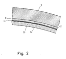
- FIG. 2 shows in section II-II the arrangement of the device within the GRP carrier tube 5.
- the shielding tube end section 11b is inserted into this carrier tube, which carries the RF shield 20 on its outside 25.
- This RF shield 20 consists of a brass wire mesh with a mesh size of 0.35 mm.
- a rubber insulation 26, which is adapted to the inner wall 27 of the carrier tube 5, is placed around the HF shielding 20.
- Fig. 3 shows an enlarged view of section III of Fig. 1. It can be seen in Fig. 3 that the shielding tube end portion 11a with its inner end 12, the applied RF shielding 20 and the rubber insulation 26 is held in the support tube 5 .
- the gaps between the individual parts are only shown to improve the clarity of the drawing; in reality, parts 11a, 20, 26 and 5 are in direct contact with one another.
- a ring 29 made of glass fiber reinforced plastic, to which the rubber flange 13 is fixed with its outer edge 31 by means of a screw 30.
- an annular disk-shaped part 20a of the HF shield approximately corresponding to the rubber flange 13 is placed.
- the inner edge 14 of the rubber flange 13 lies between a ring 33 made of glass fiber reinforced plastic, which is placed on the axial end 15 of the shielding tube center section 16.
- Another GRP ring 34 is connected to the middle section 16.
- the ring 34 is screwed into the shielding tube middle section 16 by means of radially extending screws 35.
- a clamping screw 36 extends, with which the rings 33 and 34 and between them the shields 20a and 20b and the inner edge 14 of the rubber flange 13 can be pressed together. In this way, a detachable but highly conductive connection between the rubber flange 13 and the tubes 16 and 17 is brought about.
- a plurality of screws 35 and 36 are distributed around the circumference of the edge 14. The same also applies to the screws 30 on the outer edge 31 of the rubber flange 13.
- Fig. 4 shows the connection of the shielding or patient chamber 18 to the device extending through the magnet 3. It is necessary to shield this patient or shielding chamber 18, in which operating personnel must also be located, from the magnet 3 with the same high frequency as the device.
- the end section 11a is pulled with a piece 41 a little beyond the outer end 5a on the side a.
- a GRP ring 42 is pushed, which by means of a radial screw 43 is screwed to the end piece 41.
- the shield 20 between the outer side 44 of the end section 11a and the ring 42 is clamped in a pressing manner.
- In front of the end piece 41 there is a wall 45 of the shielding chamber 18, which is provided with a shield 20c towards the end section 11a.
- This shield 20c can be clamped between two copper rings 46a and 46b by means of a schematically indicated screw connection 47.
- the shield 20 is soldered onto the outside 48 of the copper ring 46b. In this way, a safe, but removable, shielding is provided between the shielding chamber 18 and the shielding 20 of the device.
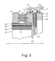
- FIG. 5 shows the structure of the end flange at the end b of the device according to FIG. 1.
- the carrier tube end 5b again surrounds the rubber insulation 26, the RF shielding 20 and the shielding tube end section 11b in an end region 51 outside the magnet 3.
- the end region 41 protrudes beyond the axial end 5b of the carrier tube 5.
- the end region 41 is surrounded by a GRP reinforcement ring 52 made of glass fiber reinforced plastic, which is connected all around with radially projecting flanges 54 by means of a schematically illustrated screw connection 53.
- a GRP reinforcement ring 52 made of glass fiber reinforced plastic, which is connected all around with radially projecting flanges 54 by means of a schematically illustrated screw connection 53.
- the shield 20 is placed over the outer flank 57 of the reinforcing ring 52.
- You are outside Copper end flange 58 opposite, which is provided over the entire area towards the patient interior 22 with a shield 20d which extends over the outer edge 59 of the end flange 58.
- Another outer reinforcement ring 60 made of glass fiber reinforced plastic serves as the outer end of the end flange 58, which is also connected to radially protruding angles 61 via a schematically illustrated screw connection 62. Both radially outwardly protruding angles 54, 61 are connected by means of rubber tensioning elements 63 which press the outer reinforcing ring 60 against the inner reinforcing ring 52 by contacting the copper end flange 58 with the shield 20 and with the shield 20d.
- the shield tube end section 11b is flattened on its underside 11c with respect to the shield tube end section 11a.
- the flattening below the underside 11c results in the possibility of arranging a cable duct 64, which can be seen in FIG. 1 and through which supply or measurement leads can be routed to the gradient tube 17.
Landscapes
- Physics & Mathematics (AREA)
- Condensed Matter Physics & Semiconductors (AREA)
- General Physics & Mathematics (AREA)
- Health & Medical Sciences (AREA)
- Epidemiology (AREA)
- Magnetic Resonance Imaging Apparatus (AREA)
Applications Claiming Priority (2)
| Application Number | Priority Date | Filing Date | Title |
|---|---|---|---|
| DE3833592A DE3833592A1 (de) | 1988-10-03 | 1988-10-03 | Vorrichtung zur geraeuschdaempfung und hochfrequenz-abschirmung des patienten-aufnahmeraumes im feld des magneten eines mr-tomographiegeraetes |
| DE3833592 | 1988-10-03 |
Publications (1)
| Publication Number | Publication Date |
|---|---|
| EP0364019A1 true EP0364019A1 (fr) | 1990-04-18 |
Family
ID=6364280
Family Applications (1)
| Application Number | Title | Priority Date | Filing Date |
|---|---|---|---|
| EP89202424A Withdrawn EP0364019A1 (fr) | 1988-10-03 | 1989-09-27 | Dispositif d'amortissement de bruit et écran à haute fréquence pour l'ouverture d'examen d'un appareil de tomographie par RM |
Country Status (3)
| Country | Link |
|---|---|
| EP (1) | EP0364019A1 (fr) |
| JP (1) | JPH02143509A (fr) |
| DE (1) | DE3833592A1 (fr) |
Cited By (2)
| Publication number | Priority date | Publication date | Assignee | Title |
|---|---|---|---|---|
| EP0825450A3 (fr) * | 1996-08-22 | 1999-12-29 | Esaote S.p.A. | Dispositif de blindage électromagnétique pour appareils de résonance magnétique nucléaire |
| EP0981057A3 (fr) * | 1998-08-14 | 2001-10-17 | General Electric Company | Assemblage d'aimants pour l'IRM avec une paroi intérieure non-conductrice |
Families Citing this family (7)
| Publication number | Priority date | Publication date | Assignee | Title |
|---|---|---|---|---|
| DE19838390A1 (de) * | 1998-08-24 | 2000-03-02 | Siemens Ag | Lärmreduziertes diagnostisches Magnetresonanzgerät |
| GB9923648D0 (en) * | 1999-10-07 | 1999-12-08 | Magnex Scient Limited | Acoustic liner |
| JP4551522B2 (ja) * | 2000-02-07 | 2010-09-29 | 株式会社東芝 | Mri装置 |
| EP1728087B1 (fr) * | 2004-03-15 | 2008-05-28 | Koninklijke Philips Electronics N.V. | Blindage contre les courants de foucault perfore pour aimant principal dans dispositif d'imagerie par resonance magnetique |
| US8212564B2 (en) | 2007-06-14 | 2012-07-03 | Hitachi Medical Corporation | Open magnetic resonance imaging apparatus |
| JP5752393B2 (ja) * | 2010-11-01 | 2015-07-22 | 株式会社東芝 | 超電導磁石装置 |
| DE102012203450B4 (de) * | 2012-03-05 | 2015-03-12 | Siemens Aktiengesellschaft | Magnetresonanzeinrichtung mit einer zylindrischen Patientenaufnahme und Patientenkapsel |
Citations (1)
| Publication number | Priority date | Publication date | Assignee | Title |
|---|---|---|---|---|
| EP0157404A2 (fr) * | 1984-04-06 | 1985-10-09 | General Electric Company | Salle blindée contre des hautes fréquences pour un système d'image utilisant la résonance nucléaire-magnétique |
-
1988
- 1988-10-03 DE DE3833592A patent/DE3833592A1/de not_active Withdrawn
-
1989
- 1989-09-27 EP EP89202424A patent/EP0364019A1/fr not_active Withdrawn
- 1989-10-02 JP JP1257613A patent/JPH02143509A/ja active Pending
Patent Citations (1)
| Publication number | Priority date | Publication date | Assignee | Title |
|---|---|---|---|---|
| EP0157404A2 (fr) * | 1984-04-06 | 1985-10-09 | General Electric Company | Salle blindée contre des hautes fréquences pour un système d'image utilisant la résonance nucléaire-magnétique |
Non-Patent Citations (1)
| Title |
|---|
| PATENT ABSTRACTS OF JAPAN, Band 10, Nr. 111 (P-451)[2168], 25. April 1986; & JP-A-60 242 350 (SANYO DENKI K.K.) 02-12-1985 * |
Cited By (2)
| Publication number | Priority date | Publication date | Assignee | Title |
|---|---|---|---|---|
| EP0825450A3 (fr) * | 1996-08-22 | 1999-12-29 | Esaote S.p.A. | Dispositif de blindage électromagnétique pour appareils de résonance magnétique nucléaire |
| EP0981057A3 (fr) * | 1998-08-14 | 2001-10-17 | General Electric Company | Assemblage d'aimants pour l'IRM avec une paroi intérieure non-conductrice |
Also Published As
| Publication number | Publication date |
|---|---|
| JPH02143509A (ja) | 1990-06-01 |
| DE3833592A1 (de) | 1990-04-05 |
Similar Documents
| Publication | Publication Date | Title |
|---|---|---|
| DE19511796C2 (de) | Kopfantenne für Magnetresonanzuntersuchungen | |
| EP0156042B1 (fr) | Disposition de bobine à haute fréquence pour transmettre et/ou recevoir des champs magnétiques alternatifs | |
| DE4422782C2 (de) | Aktiv geschirmte transversale Gradientenspule für Kernspintomographiegeräte | |
| DE3807178A1 (de) | Magnetresonanz-bildgeraet | |
| DE10049414C2 (de) | Magnetresonanzgerät mit einer Schallisolierung | |
| EP0067933A1 (fr) | Electro-aimant pour tomographie par RMN | |
| DE3511750A1 (de) | Spulenanordnung fuer kernspinuntersuchungen | |
| DE4226814A1 (de) | Spulenanordnung für MR-Untersuchungen der Mamma | |
| DE3833592A1 (de) | Vorrichtung zur geraeuschdaempfung und hochfrequenz-abschirmung des patienten-aufnahmeraumes im feld des magneten eines mr-tomographiegeraetes | |
| DE102006058329A1 (de) | Magnetresonanzsystem | |
| EP0243669B1 (fr) | Structure-cache d'un système magnétique d'une installation d'imagerie par résonance magnétique nucléaire | |
| DE102006049066A1 (de) | HF-Abschirmverfahren, MR-Bildgebungsvorrichtung und Sende/Empfangs-Oberflächenspule | |
| DE102010064096A1 (de) | Magnetresonanzspulenvorrichtung | |
| EP1946736A1 (fr) | Dispositif de thérapie par vibrations | |
| DE102012210280B4 (de) | Hochfrequenzspulenvorrichtung | |
| EP0222281A1 (fr) | Appareil d'imagerie par résonance magnétique nucléaire | |
| WO1985005448A1 (fr) | Tomographe a resonance de spin | |
| DE19639977A1 (de) | Medizinisches Röntgensystem | |
| DE19749903A1 (de) | Aktives elektrisches Gerät mit einer elektrischen Zuleitung zum Betrieb im Untersuchungsvolumen eines Kernspintomographiegerätes | |
| DE102008041465A1 (de) | Balun für Kernspintomographen | |
| DE102005013853B4 (de) | Magnetresonanzanlage mit einer Hochfrequenz-Sendeantenne | |
| DE10306998B3 (de) | Hochfrequenzantenne für eine Magnetresonanzanlage | |
| DE1938722B2 (de) | Kernresonanz-sondensystem | |
| DE10214111A1 (de) | Shimkasten, Gradientenspulensystem und Magnetresonanzgerät zum Aufnehmen des Shimkastens | |
| DE10346275B4 (de) | Erzeuger zeitvariabler Magnetfelder eines Magnetresonanzgeräts und Magnetresonanzgerät mit dem Erzeuger |
Legal Events
| Date | Code | Title | Description |
|---|---|---|---|
| PUAI | Public reference made under article 153(3) epc to a published international application that has entered the european phase |
Free format text: ORIGINAL CODE: 0009012 |
|
| AK | Designated contracting states |
Kind code of ref document: A1 Designated state(s): DE FR GB NL |
|
| 17P | Request for examination filed |
Effective date: 19901016 |
|
| STAA | Information on the status of an ep patent application or granted ep patent |
Free format text: STATUS: THE APPLICATION IS DEEMED TO BE WITHDRAWN |
|
| 18D | Application deemed to be withdrawn |
Effective date: 19920331 |