EP0364192A2 - Befestigungsvorrichtung zum Festklemmen eines Sattels in die richtige Lage - Google Patents
Befestigungsvorrichtung zum Festklemmen eines Sattels in die richtige Lage Download PDFInfo
- Publication number
- EP0364192A2 EP0364192A2 EP89310306A EP89310306A EP0364192A2 EP 0364192 A2 EP0364192 A2 EP 0364192A2 EP 89310306 A EP89310306 A EP 89310306A EP 89310306 A EP89310306 A EP 89310306A EP 0364192 A2 EP0364192 A2 EP 0364192A2
- Authority
- EP
- European Patent Office
- Prior art keywords
- clamp
- seat
- tube
- post
- clamping
- Prior art date
- Legal status (The legal status is an assumption and is not a legal conclusion. Google has not performed a legal analysis and makes no representation as to the accuracy of the status listed.)
- Withdrawn
Links
Images

Classifications
-
- B—PERFORMING OPERATIONS; TRANSPORTING
- B62—LAND VEHICLES FOR TRAVELLING OTHERWISE THAN ON RAILS
- B62J—CYCLE SADDLES OR SEATS; AUXILIARY DEVICES OR ACCESSORIES SPECIALLY ADAPTED TO CYCLES AND NOT OTHERWISE PROVIDED FOR, e.g. ARTICLE CARRIERS OR CYCLE PROTECTORS
- B62J1/00—Saddles or other seats for cycles; Arrangement thereof; Component parts
- B62J1/08—Frames for saddles; Connections between saddle frames and seat pillars; Seat pillars
Definitions
- This invention concerns a clamp assembly for clamping a seat, such for example as a bicycle seat, in position.
- seat post clamps for attaching the seat of the bicycle to a seat post have heretofore been formed of a complicated casting which is relatively complicated and expensive to manufacture and which is not all that easily adjusted by the owner/rider.
- Such clamps are typified by the construction shown in US-A-4,142,813.
- a clamp assembly for clamping a seat in position comprising a post to one end of which there is secured a clamp tube whose axis is substantially perpendicular to that of the post; a clamp device which is mounted in the clamp tube and which has a plurality of separate parts between which seat support means may be disposed; and clamp means for clamping the separate parts together so as to clamp the seat support means therebetween and simultaneously to clamp the clamp device as a whole to the clamp tube.
- the construction is such that, when the clamp means are operated to effect the said clamping, the effective outer diameter of at least a portion of the clamp device is increased so as to force it into clamping contact with the internal surface of the clamp tube.
- each of said separate parts may have a wedging surface which is engageable with a wedging surface of one of the other separate parts or with the seat support means, each said wedging surface extending obliquely with respect to the axis of the clamp tube.
- Each wedging surface is preferably a planar surface extending from an end of the clamp device to a central part of the outer circumference of the latter.
- the clamp means may be constituted by a single bolt which passes through holes in the separate parts.
- the clamp tube has an axially extending slot therein which extends between opposite ends of the clamp tube, the clamp means when operated reducing the effective internal diameter of the clamp tube.
- the assembly may also comprise a seat provided with seat support means disposed between the said separate parts.
- the seat support means may comprise two substantially parallel seat mounting rails.
- planar surfaces may be provided with grooves in which the seat mounting rails are disposed.
- the grooves are preferably substantially perpendicular to the axis of the clamp tube.
- the clamp assembly of the present invention may be easily and inexpensively manufactured, e.g. from common materials, and may easily be adjusted by a rider of a bicycle provided with such a clamp assembly.
- the clamp tube may be constituted by a simple piece of round tubing which is welded or otherwise permanently attached perpendicularly to the top of the said post.
- the clamp device may comprise a piece of cylindrical rod having a diameter slightly less than the inside diameter of the clamp tube, the said piece being sliced into three sections.
- Two wedge-like clamping sections may be formed in the said piece by making two cuts therein each of which runs from the central part of the circumference of the rod to terminate at an end of the rod near a diameter thereof, thus forming two wedge-like clamping sections and a main section.
- the three pieces may then be axially drilled to provide holes through which passes a bolt, the holes having a slightly larger diameter than that of the bolt.
- Two parallel grooves generally perpendicular to the axis of the rod may be provided in the cut surfaces on the main section for accommodating two parallel rails of the seat.
- a two piece clamp device is made of identical parts and is drawn together by a bolt, thereby trapping the seat rails therebetween and expanding the clamp device to grip the inside of the clamp tube.
- a two piece clamp device clamps the seat rails therebetween.
- the clamp tube has a longitudinally oriented split and a suitable clamp means which decreases the internal diameter of the clamp tube to grip the clamp device.
- a single wedge clamp device clamps the seat rails with the assistance of a keeper at the non-wedge end of the clamp device and is drawn together by a bolt, thereby trapping the seat rails and expanding the clamp device to grip the inside of the clamp tube.
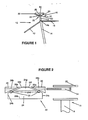
- FIG. 1 there is shown a bicycle 12 provided with a clamp assembly 10 according to the present invention, the clamp assembly being provided for clamping a seat 32 in position.
- the clamp assembly comprises a seat post 18 which is adjustably mounted in a seat tube 14 having a clamp 14a at the top thereof by means of which the seat post 18 is clamped to the seat tube 14.
- the seat tube 14 is supported by a seat stay tube 13 and a top tube 15.
- the seat post 18 has a clamp tube 20 which is attached perpendicularly to the top of the seat post 18 by welding or other conventional joining technique.
- a clamp device 22 (best seen in Figure 2) is mounted in the clamp tube 20 and is formed from a piece of cylindrical rod which is cut into three separate parts or sections; a main section 24 and clamping sections 26 and 28.
- a bolt or other fastening member 34 is inserted through holes 28b, 24g and 26b in the clamping section 28, the main section 24 and the clamping section 26 respectively, the hole 28b being threaded.
- At least the hole 24g has a diameter greater than that of the bolt 34 so that when the bolt 34 is tightened, the wedging action of the clamping sections 26 and 28 on the main section 24 serves to clamp the seat rails 30 in the grooves 24d and also simultaneously serves to expand the outer diameter of the clamp device 22 to snugly engage and clamp against the inside of the clamp tube 20, thereby fixing the angle of the seat 32 relative to the seat post 18 as well as the fore-aft position of the seat 32 relative to the seat post 18 and the bicycle frame.
- the hole 24g may also have a cross-section of an upwardly facing U-shaped slot such that the open side of the slot extends through the upper surface of the main section 24.
- FIG. 3 A second embodiment 110 is shown in Figure 3.
- the Figure 3 embodiment is quite similar to the Figure 1 and 2 embodiment and operates in a generally similar fashion with the exception that slots 124d, which correspond to slots 24d of Figure 2, open axially outwardly rather than upwardly.
- a third embodiment of the present invention is shown in Figure 4 and is generally designated 210.
- a seat post member 216 Inserted into the seat tube 14 of a conventional bicycle such as that shown in Figure 1 is a seat post member 216 comprised of a seat post 218 and a clamp tube 220 which is attached perpendicularly to the top of the seat post 218 by welding or other conventional joining technique.
- a clamp device 222 which is disposed in the clamp tube 220, is formed from two, preferably identical, members 224 which are formed by machining, casting, forging or other conventional manufacturing techniques.
- Each member 224 has a rail slot end 224b, a wedge end 224c and a circumference 224a.
- a slot 224d is formed in the rail slot end 224b to accommodate and clamp a respective seat rail 30 of the seat 32.
- a bolt or either fastening member 234 is inserted through holes 224g in the clamping members 224, the hole 224g in one of the clamping members 224 being threaded if desired rather than utilizing a nut 236.
- the bolt 234 is tightened, the wedging action of wedge sections 224h on the seat rails 30 disposed in the grooves 224d clamps the seat rails 30 and also simultaneously serves to expand the outer diameter of the clamp device 222 to snugly engage and clamp against the inside of the clamp tube 220, thereby fixing the angle of the seat 32 relative to seat post 218 as well as the fore-aft position of the seat 32 relative to the seat post 218 and the bicycle frame.
- a fourth embodiment of the present invention is shown in Figure 5 and is generally designated 310.
- a seat post member 316 Inserted into the seat tube 14 of a conventional bicycle such as that shown in Figure 1 is a seat post member 316 comprising a seat post 318 and a clamp tube 320 which is attached perpendicularly to the top of the seat post 318 by welding or other conventional joining technique.
- a clamp device 322 is disposed in the clamp tube 320 and is formed from three members 324, 326, 328.
- Main member 324 is generally cylindrical in nature and has a portion cut off (or formed by other conventional manufacturing techniques) to produce wedge 326.
- the member 324 has a rail slot end 324b, a keeper end 324c, and an outer circumference 324a. Slots 324d are formed in the rail slot end 324b and the keeper end 324c to accommodate and clamp the seat rails 30 of the seat 32.
- Keeper 328 can be formed from a washer or similar piece.
- a bolt or other fastening member 334 is inserted through holes 334a, 324g and 326a in keeper 328 and clamping members 324 and 326 respectively.
- the hole 326a in the member 326 may be threaded if desired.
- the wedging action of a wedge surface 326b of the wedge 326 on a wedge surface 324c of the clamping member 324 clamps one of seat rails 30 in one groove 324d while the keeper 328 clamps the other seat rail 30 into the other slot 324d and also simultaneously serves to expand the outer diameter of the clamp device 322 to snugly engage and clamp against the inside of the clamp tube 320, thereby fixing the angle of the seat 32 relative to seat post 318 as well as the fore-aft position of the seat 32 relative to the seat post 318 and the bicycle frame.
- a fifth embodiment of the present invention is shown in Figures 6 and 7 and is generally designated 410.
- a seat post member 416 Inserted into the seat tube 14 of a conventional bicycle such as that shown in Figure 1 is a seat post member 416 comprised of a seat post 418 and a clamp tube 420 which is attached perpendicularly to the top of seat post 418 by welding or other conventional joining technique.
- An axially extending slot 420a is cut along one side of tube 420 so as to extend between opposite ends of the clamp tube 420.
- the slot 420a has located on either side thereof ears 420b and 420c. This construction may also be formed by making the clamp tube 420 as an extrusion.
- a clamp device 422 which is disposed in the clamp tube 420 is formed from two members 424 and 426 which are formed by machining, casting, forging or other conventional manufacturing techniques.
- the member 424 has an outer circumference 424a.
- Two slots 424d are formed in a face 424e of the member 424 to accommodate and clamp the seat rails 30 of the seat 32.
- the member 426 is constituted by a keeper which is formed by slicing off a portion of member 424 or otherwise.
- a bolt or other fastening member 434 is inserted through holes in the ears 420b and 420c in the clamp tube 420.
- the hole in one of the ears may be threaded if desired or a nut 436 may be utilized.
- This clamping also serves simultaneously to contract the inner diameter of the clamp tube 420 to snugly engage and clamp the outside of the clamp device 422, thereby fixing the angle of the seat 32 relative to seat post 418 as well as the fore-aft position of the seat 32 relative to the seat post 418 and the bicycle frame.
Landscapes
- Engineering & Computer Science (AREA)
- Mechanical Engineering (AREA)
- Clamps And Clips (AREA)
- Supports For Pipes And Cables (AREA)
Applications Claiming Priority (6)
| Application Number | Priority Date | Filing Date | Title |
|---|---|---|---|
| US25666088A | 1988-10-12 | 1988-10-12 | |
| US256660 | 1988-10-12 | ||
| US28260388A | 1988-12-12 | 1988-12-12 | |
| US282603 | 1988-12-12 | ||
| US38975189A | 1989-08-04 | 1989-08-04 | |
| US389751 | 1989-08-04 |
Publications (2)
| Publication Number | Publication Date |
|---|---|
| EP0364192A2 true EP0364192A2 (de) | 1990-04-18 |
| EP0364192A3 EP0364192A3 (de) | 1990-09-05 |
Family
ID=27400980
Family Applications (1)
| Application Number | Title | Priority Date | Filing Date |
|---|---|---|---|
| EP19890310306 Withdrawn EP0364192A3 (de) | 1988-10-12 | 1989-10-09 | Befestigungsvorrichtung zum Festklemmen eines Sattels in die richtige Lage |
Country Status (3)
| Country | Link |
|---|---|
| EP (1) | EP0364192A3 (de) |
| JP (1) | JPH02185876A (de) |
| CA (1) | CA2000414A1 (de) |
Families Citing this family (1)
| Publication number | Priority date | Publication date | Assignee | Title |
|---|---|---|---|---|
| WO1992014046A1 (fr) * | 1991-02-05 | 1992-08-20 | Hitachi Construction Machinery Co., Ltd. | Systeme pour reguler la frequence de rotation d'un moteur primaire dans un vehicule a commande hydraulique |
Family Cites Families (4)
| Publication number | Priority date | Publication date | Assignee | Title |
|---|---|---|---|---|
| FR2275353A1 (fr) * | 1974-06-21 | 1976-01-16 | Ventura & Cie Ets | Support de selle pour bicyclette et vehicule analogue |
| FR2413996A1 (fr) * | 1978-01-10 | 1979-08-03 | Patriarca Jean | Perfectionnements aux supports reglables pour selles de cycles |
| IT1111326B (it) * | 1978-09-27 | 1986-01-13 | Sella Italia Snc Di Bigolin & | Sella per bicicletta con reggisella regolabile incorporato |
| FR2529851A1 (fr) * | 1982-07-08 | 1984-01-13 | Simplex Ets | Tige de selle pour bicyclettes et vehicules similaires |
-
1989
- 1989-10-09 EP EP19890310306 patent/EP0364192A3/de not_active Withdrawn
- 1989-10-11 CA CA 2000414 patent/CA2000414A1/en not_active Abandoned
- 1989-10-12 JP JP26606489A patent/JPH02185876A/ja active Pending
Also Published As
| Publication number | Publication date |
|---|---|
| CA2000414A1 (en) | 1990-04-12 |
| EP0364192A3 (de) | 1990-09-05 |
| JPH02185876A (ja) | 1990-07-20 |
Similar Documents
| Publication | Publication Date | Title |
|---|---|---|
| US9845126B2 (en) | Seat attachment device | |
| CN1353065A (zh) | 一种用于固定自行车座支柱的夹具 | |
| CN100390013C (zh) | 自行车座位组件 | |
| US20040037639A1 (en) | Versatile guide rail clamp | |
| EP0898541A1 (de) | Rahmen mit zentralem balken und gegenüberliegende verkleidungen | |
| US6322286B1 (en) | Vibrating screed and method of making same | |
| CA2250521A1 (en) | A clamping device for clamping of tubes or the like | |
| US5033790A (en) | Seat post assembly | |
| MXPA05001028A (es) | Soporte de separacion o montaje de bastidor auxiliar y ensamble de arandela de retencion. | |
| US20060152045A1 (en) | Bicycle seat post | |
| EP0364192A2 (de) | Befestigungsvorrichtung zum Festklemmen eines Sattels in die richtige Lage | |
| US4772153A (en) | Strong tightening device used for bicycle's frame joint | |
| US20050012365A1 (en) | Bicycle seat post | |
| EP0767298B1 (de) | Befestigungsvorrichtung für einen Hochtemperatur-Wärmetauscher | |
| US6074123A (en) | Bicycle stem with enclosed steering tube clamp | |
| PT826887E (pt) | Dispositivo de ligacao | |
| FR2668744A1 (fr) | Poignee pour l'aide a l'apprentissage de la conduite des bicyclettes. | |
| SE527655C2 (sv) | Lastbärande konsol, avsedd att monteras på en längsgående takreling på ett motorfordon | |
| JP3713600B2 (ja) | 金型部品固定用鋳型床の結合構造 | |
| US20020166941A1 (en) | Seat post | |
| JP3305618B2 (ja) | 部材同士の締結構造 | |
| FR2617547A3 (fr) | Element de serrage et fixation, et procede pour relier des plaques-sandwich | |
| KR970000445B1 (ko) | 평판고정장치 | |
| CA1254364A (en) | Structure clamp | |
| JPH0564123U (ja) | ガイドパイプホルダ |
Legal Events
| Date | Code | Title | Description |
|---|---|---|---|
| PUAI | Public reference made under article 153(3) epc to a published international application that has entered the european phase |
Free format text: ORIGINAL CODE: 0009012 |
|
| AK | Designated contracting states |
Kind code of ref document: A2 Designated state(s): AT CH DE FR GB IT LI |
|
| PUAL | Search report despatched |
Free format text: ORIGINAL CODE: 0009013 |
|
| AK | Designated contracting states |
Kind code of ref document: A3 Designated state(s): AT CH DE FR GB IT LI |
|
| 17P | Request for examination filed |
Effective date: 19910220 |
|
| 17Q | First examination report despatched |
Effective date: 19920520 |
|
| STAA | Information on the status of an ep patent application or granted ep patent |
Free format text: STATUS: THE APPLICATION IS DEEMED TO BE WITHDRAWN |
|
| 18D | Application deemed to be withdrawn |
Effective date: 19931211 |