EP0364198A2 - Kühlfahrzeuge und -container - Google Patents
Kühlfahrzeuge und -container Download PDFInfo
- Publication number
- EP0364198A2 EP0364198A2 EP89310313A EP89310313A EP0364198A2 EP 0364198 A2 EP0364198 A2 EP 0364198A2 EP 89310313 A EP89310313 A EP 89310313A EP 89310313 A EP89310313 A EP 89310313A EP 0364198 A2 EP0364198 A2 EP 0364198A2
- Authority
- EP
- European Patent Office
- Prior art keywords
- bulkhead
- container
- sliders
- rails
- secured
- Prior art date
- Legal status (The legal status is an assumption and is not a legal conclusion. Google has not performed a legal analysis and makes no representation as to the accuracy of the status listed.)
- Withdrawn
Links
Images



Classifications
-
- B—PERFORMING OPERATIONS; TRANSPORTING
- B60—VEHICLES IN GENERAL
- B60P—VEHICLES ADAPTED FOR LOAD TRANSPORTATION OR TO TRANSPORT, TO CARRY, OR TO COMPRISE SPECIAL LOADS OR OBJECTS
- B60P3/00—Vehicles adapted to transport, to carry or to comprise special loads or objects
- B60P3/20—Refrigerated goods vehicles
- B60P3/205—Refrigerated goods vehicles with means for dividing the interior volume, e.g. movable walls or intermediate floors
-
- B—PERFORMING OPERATIONS; TRANSPORTING
- B61—RAILWAYS
- B61D—BODY DETAILS OR KINDS OF RAILWAY VEHICLES
- B61D45/00—Means or devices for securing or supporting the cargo, including protection against shocks
- B61D45/006—Fixing by movable walls
Definitions
- This invention relates to refrigerated vehicles such as lorries, trailers, semi-trailers and vans and to containers for such vehicles and in particular to refrigerated vehicles or containers with a load-carrying space which is divided into a number of compartments.
- the division of the load-carrying space of a refrigerated vehicle or container is carried out with partitions, normally in the form of an insulating panel, known as bulkheads.
- the bulkheads may be fixed in position or they may be capable of being secured in a number of different sizes.
- One design of movable bulkhead had two positions, a vertical position in which it forms the compartments and a horizontal position adjacent the roof in which it can be moved along the load-carrying space.
- the bulkhead in this arrangement is hinged to struts which connect it to a sliding frame.
- the hinges and struts co-operate to allow the bulkhead to be moved between two positions.
- the sliding frame includes slides which can move within rails secured along the longitudinal walls of the load-carrying space when the bulkhead is in the horizontal position, to allow its location within the vehicle or container to be changed.
- Bulkheads are provided with seals on all four edges. These are arranged so that when the bulkhead is in the vertical position, the top and bottom seals are compressed between the bulkhead and the roof and floor respectively of the refrigerated vehicle or container.
- the side seals are not compressed when the bulkhead is swung into the vertical position, rather these are mounted on movable supports which can be forced, by means of locking devices, towards the walls of the load-carrying space to compress the side seals.
- the sliders of the sliding frame comprise wheels, normally in the form of ball-bearings, which move within a C-shaped metal rails secured along the longitudinal walls of the vehicle.
- the compartments into which the bulkheads divide the load-carrying space often need to be kept at different temperatures, for example, to allow perishable and frozen goods to be carried in the same vehicle or container.
- One arrangement for achieving this is to provide an evaporator at one end of the container or vehicle and employ bulkheads which have at least one passage therethrough, each passage containing a fan, the passages being closed by shutters.
- the compartment in which the evaporator is located is then kept at the coldest temperature and when it is desired to cool one of the other compartments, the passages in the bulkheads between it and the coldest compartment are opened and the fans activated to force cold air from the coldest compartment into that which it is desired to cool.
- the bulkheads may also be provided with a heater, and the passages and fans so arranged that air can be sucked out of the compartment, passed over the heater and returned to the compartment.
- the fans require power to drive them as do the heater and the shutters if these are electrically operated and in some known bulkheads this is supplied by means of a coiled cable, known as a "Susie" cable, and socket on the bulkhead, and a series of sockets along the container wall all connected to a power supply.
- the plurality of sockets is required to allow two or more bulkheads to be supplied with power in a number of positions within the container. This arrangement has several drawbacks. Firstly, it is necessary to unplug and replug the 'susie' cable from the wall sockets each time the bulkhead position is changed.
- the 'susie' cable can be snagged on the top of the goods carried in the container resulting in a bad connection or even causing it to break.
- the provision of the plurality of sockets adds to the expense of the container and the sockets themselves either intrude into the load-carrying space or must be set into the walls of the container which reduces the insulation in these areas.
- a cable is permanently connected between the bulkhead and a power supply at one end of the container or vehicle.
- This arrangement obviates the need for sockets but can only be employed in a vehicle with a single movable bulkhead. Moreover the same problem with regard to snagging occur.
- a refrigerated vehicle or container in accordance with the invention has at least one bulkhead for dividing the load-carrying space of the vehicle or container, the bulkhead(s) being mounted on a frame which has two sliders secured thereto, each slider being slidable along an aperture which extends along a rail secured to each of the longitudinal walls of the load-carrying space of the vehicle or container, the sliders and rail being formed from a plastics material and the apertures and sliders being dimensioned so that the sliders are a close fit in the apertures.
- the advantage of forming the sliders and rails from plastics material is that the sliders can move easily and smoothly within the apertures but since plastic materials are much worse heat conductors than metal heat losses between the compartments either side of the bulkhead via the sliders and rails are minimised.
- plastic materials are much worse heat conductors than metal heat losses between the compartments either side of the bulkhead via the sliders and rails are minimised.
- an electrically conductive rod is secured to each of the rails, one rod being connected to the negative pole of an electrical power supply and the other rod being connected to the positive pole, a conductive member being provided in or on each slider, the conductive members being electrically connected to one or more electrical devices supported on or in the bulkhead, the arrangement being such that when the bulkhead is in a position in which it divides the load-carrying space, each conductive member is in contact with a rod whereby power is supplied to the electrical device(s).
- This arrangement has the advantage that it does not include either sockets or cables and therefore does not have the problems associated with these.
- power is always automatically supplied to the electrical device when the bulkhead is in the position to form compartments and there is no need to unplug or replug when the bulkhead is to be moved. It is relatively simple in construction and consequently inexpensive.
- the rods may be secured within the apertures of the rails, with the sliders suitably dimensioned and shaped so that they do not snag on the rods. This means that the rods are protected from damage, and to a great extent from being touched accidentally and further insulation of the rods is not normally required since the heat insulative materials of which the rails are made is frequently often electrically insulative.
- the conductive members suitably take the form of carbon brushes held within an aperture within the slider and biased by a spring such that the brush will contact the rail.
- the connection between the brush and the electrical device may comprise a cable passing between the two through the slider and the bulkhead.
- the electrical device may, for example, be a fan, heater or shutter or a plurality of one or more of these.
- the bulkhead is arranged so that it can be moved between a horizontal position in which it can be moved lengthwise down the container and a vertical position in which it forms the compartments.
- the sliders are so dimensioned that when the bulkhead is in the vertical position, a part of each of the sliders is in the aperture of that part of the rails immediately adjacent the bulkhead.
- the sliders when the bulkhead is in the vertical position, are a distance in front of the bulkhead so that the aperture in the portion of the rail adjacent the bulkhead is open.
- the bulkhead comprises a panel of insulating material, seals being provided along each edge of the panel.
- the seals may be formed from rubber and be carried by metal support mounted to the bulkhead.
- the bulkhead is preferably dimensioned so that when it is in the vertical position, the top and bottom seals are compressed but the side seals are not.
- the side seals are therefore suitably provided with supports which can be moved relative to the bulkhead to compress the seals.
- the rails are secured in the upper corners of the load space and are configured so that, when in place, each of the upper corners has a smooth curved profile. This allows the seals to fit closely against the rails and adjacent portions of the load space. With the plastics materials from which the rails are made this is simple and inexpensive to achieve whereas with the metal rails in known arrangements this would add considerably to the cost.
- the bulkhead 2 shown in the Figures comprises a panel of insulating material with a skin of metal or plywood secured to each side by adhesive.
- the skin is itself coated with a glass fibre reinforced polyester to render it waterproof. All four edges of the bulkhead are provided respectively with seals, 4, 6, 8 and 10 which are shown in dotted outline in Figure 2.
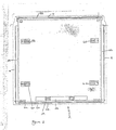
- the bulkhead 2 is employed to partition the interior of a refrigerated vehicle or container, the perimeter of the load-carrying space of which is indicated at 12 in Figure 1. As shown in Figures 1, 4 and 5 the bulkhead has two aluminium mounts 14 bolted thereto each of which has a triangular portion 16 which extends outwards from the bulkhead.
- the mounts 14 also include a keeper assembly 18, through which is passed a swivel shaft 20. The bulkhead 2 swivels around these shafts 20 when moving from the horizontal to the vertical position or vice-versa as described below.
- Each sliding frame 22 comprises an elongated three sided housing 24 which is secured at one end to each end of the associated swivel shaft 20 (see Figure 1).
- One end 25 of the strut 26 is secured at its other end to the tip of the triangular extension 16 of the associated mount 14.
- the sliding frames 22 also include sliders 28, in the form of rectangular cross-section rods, which are screwed (see 30) to the housings 24.
- the sliders 28 move within apertures 31 provided in rails 32 which are secured by for example rivets and gluing, see 33, 35, to the upper corners of the load carrying compartment and which extend along the length thereof.
- the rails 32 and sliders 28 are both formed from materials which are poor conductors of heat, in particular the rails 32 are formed from gloss fibre reinforced polyester whilst the sliders 28 are formed from polyvinyl chloride. These two materials also allow the sliders to move easily within the rails.
- the rails 32 are suitably formed by pultrusion.
- the sliders 28 allow the bulkhead 2 to be moved to any desired position within the vehicle. Movement of the bulkhead 2 is effected when it is in the horizontal position, as shown in Figures 5 and 6 by pushing the bulkhead manually to cause the sliders to move within the apertures.
- the bulkhead 2 is moved from the vertical position shown in Figure 4 to the horizontal position by pulling handles 34 provided on kickstrip 36 upwards.
- the bulkhead 2 rotates around the shafts 20 an the connections between the triangular mount extensions 16 and the struts 26 move along a path indicated by dotted line 38 within the housings 24.
- the struts 26 extend to allow the rotation of the bulkhead and mount secured thereto. Movement from the horizontal to the vertical position is effected by pulling downwards on the handles.
- the length of the sliders 28 should be such that they extend through the apertures 31 adjacent the bulkhead 2 when the bulkhead 2 is in the vertical position. Furthermore, as can be appreciated from Figure 1 and 5 the sliders 28 and rails 32 are dimensioned so that the sliders 28 are a close fit in apertures 31. The amount of head lost via air gaps between the sliders 28 and rails 32 is therefore minimised.
- the upper and lower seals, 6 and 10, of the bulkhead 2 are fixed in place and the dimensions are such that when the bulkhead is rotated into the vertical position they are compressed between the bulkhead and the ceiling and floor.
- the seals comprise two parallel spaced tubes 40 and 42 connected by a base portion 44.
- the base portion 44 is connected to the bulkhead 2 by two spaced zig-zag strips 46,48.
- the seals are supported by channels 50, 52 which are secured at one end to the bulkhead and at theother to the base portion 44 intermediate the two zig-zag strips 46, 48 which insulate the channels.
- the seals may be formed in two halves, each half comprising a tube, base portion and a strip. The parts of each half are integral and the seals may be made of rubber.
- the side seals 4 and 8 are similar to the end seals 6 and 10 but the supporting channels 54, 56 are not secured directly to the bulkhead rather they can move relative to the bulkhead to ensure effective sealing alon the sides as described below.
- the support channels 50, 52, 54 and 56 are in the form of a U channel with the flanges having extensions parallel to the web.
- the extensions and web can be formed from a plastics material which helps to reduce even further heat transfer via the channels whilst the flanges are generally formed from aluminium to give them sufficient strength.
- the device 60 comprises a locking shaft 66 movable within a channel in the bulkhead which is secured at one end to the aluminium support channel 54. At the other end the shaft 66 is pivoted to an actuating handle 68 which comprises two hinged member 70 and 72 which in the unlocked position lie at an angle to each other. The unhinged end of member 72 is secured to the bulkhead.
- the shaft 66 moves to the left to force the channel 54 and seal 4 towards the wall of the load carrying space and compress the tubular portions 40 and 42 into a generally triangular shape to seal the sides of the bulkhead.
- the bulkhead may be locked in positin with bolts 74, holes being provided at intervals for this purpose along the wall of the load-carrying space.
- the rails are preferably made by a pultrusion process. This is the best and most inexpensive way to acheive the desired rail profile. Furthermore the direction of the reinforcement can be arranged to provide strength along the length of the rails.
- the bulkhead 2 shown in Figure 8 in the vertical position includes a fan 76 which is located in a passage which extends through the width of the bulkhead.
- the fan 76 is employed to pass air from a compartment on one side of the bulkhead 2 to that on the other.
- An evaporator is normally provided in one compartment of the vehicle or container and the fans 76 allow the other compartments to be cooled by passage of air from the compartment with the evaporator.
- two electrical cables 78 are connected to the fan 76, each of which extends from the fan to one of the sliders 28 of the bulkhead as shown in greater detail in Figure 9 which is a partially sectional view through the slider and rail at one corner of the trailer or container of Figure 8.
- Passages are preferably provided within the bulkhead for the cables or alternatively conduits for the cables can be secured to the surface of the bulkheads. However this may not be necessary and in some cases the cables can simply lie against the bulkhead and can be secured thereto by, for example, clips if necessary.
- Each cable 78 passes into an aperture in the appropriate slider 28 and is there connected to one end of a carbon brush 80, the other end of which extends above the slider 28.
- An electrically conductive rod 82 is secured within each aperture 31 of the rails 32.
- One of the rods 82 is connected to the positive pole of an external power supply, for example, the power supply of the evaporator of the refrigerated vehicle or an auxiliary supply, the other rod being connected to the negative pole.
- the sliders 28 and brushes 80 are dimensioned so that the free ends of the brushes 80 are closely adjacent the rods 82.
- a spring 84 held within the brush aperture of the slider 28 urges the brush 80 into contact with the rod 82.
- the rails 32 as discussed above are formed of a thermally insulative material. Such materials are normally also electrically insulative and no further insulation is therefore required for the rods 82. Moreover the rails 32 protects the rods 82 from damage and from being accidentally touched.
- the arrangement therefore allows for a continuous power supply to the fan 76 without the need for sockets or cables which have to stretch over the goods with consequent danger or damage.
- the arrangement can of course be used to supply power to other devices as well as, or in place, of the fan, for example, a heater or shutters.
- the bulkhead described above can further be easily moved within the refrigerated vehicle and is arranged to minimise the heat losses between the compartments which it forms specifically those which have been found to occur in know arrangements due to the apparatus provided to allow movement of the bulkhead along the container or vehicle.
Landscapes
- Engineering & Computer Science (AREA)
- Transportation (AREA)
- Mechanical Engineering (AREA)
- Physics & Mathematics (AREA)
- Thermal Sciences (AREA)
- Health & Medical Sciences (AREA)
- Public Health (AREA)
- Refrigerator Housings (AREA)
- Devices That Are Associated With Refrigeration Equipment (AREA)
Applications Claiming Priority (4)
| Application Number | Priority Date | Filing Date | Title |
|---|---|---|---|
| GB888823790A GB8823790D0 (en) | 1988-10-11 | 1988-10-11 | Improvements in & relating to refrigerated vehicles & containers |
| GB8823790 | 1988-10-11 | ||
| GB8902255 | 1989-02-02 | ||
| GB898902255A GB8902255D0 (en) | 1989-02-02 | 1989-02-02 | Improvements in and relating to multi-compartment containers or vehicles |
Publications (2)
| Publication Number | Publication Date |
|---|---|
| EP0364198A2 true EP0364198A2 (de) | 1990-04-18 |
| EP0364198A3 EP0364198A3 (de) | 1990-10-31 |
Family
ID=26294500
Family Applications (1)
| Application Number | Title | Priority Date | Filing Date |
|---|---|---|---|
| EP19890310313 Withdrawn EP0364198A3 (de) | 1988-10-11 | 1989-10-10 | Kühlfahrzeuge und -container |
Country Status (3)
| Country | Link |
|---|---|
| EP (1) | EP0364198A3 (de) |
| AU (1) | AU4278889A (de) |
| DK (1) | DK500989A (de) |
Cited By (2)
| Publication number | Priority date | Publication date | Assignee | Title |
|---|---|---|---|---|
| EP1002694A1 (de) * | 1998-11-20 | 2000-05-24 | Brandt Kühlfahrzeugbau | Kühlfahrzeug |
| CN106218479A (zh) * | 2016-08-29 | 2016-12-14 | 王云廷 | 一种恒温保鲜智能减震三轮车 |
Family Cites Families (3)
| Publication number | Priority date | Publication date | Assignee | Title |
|---|---|---|---|---|
| US2782846A (en) * | 1954-07-15 | 1957-02-26 | Bussard John Arthur | Refrigerator curtains and mountings |
| US4505126A (en) * | 1984-06-06 | 1985-03-19 | Certified Grocers Of Florida, Inc. | Food product transport system |
| GB8616502D0 (en) * | 1986-07-07 | 1986-08-13 | Dover Roller Shutters Ltd | Bulkhead door apparatus |
-
1989
- 1989-10-10 EP EP19890310313 patent/EP0364198A3/de not_active Withdrawn
- 1989-10-10 DK DK500989A patent/DK500989A/da not_active Application Discontinuation
- 1989-10-11 AU AU42788/89A patent/AU4278889A/en not_active Abandoned
Cited By (2)
| Publication number | Priority date | Publication date | Assignee | Title |
|---|---|---|---|---|
| EP1002694A1 (de) * | 1998-11-20 | 2000-05-24 | Brandt Kühlfahrzeugbau | Kühlfahrzeug |
| CN106218479A (zh) * | 2016-08-29 | 2016-12-14 | 王云廷 | 一种恒温保鲜智能减震三轮车 |
Also Published As
| Publication number | Publication date |
|---|---|
| AU4278889A (en) | 1990-04-26 |
| DK500989A (da) | 1990-04-12 |
| DK500989D0 (da) | 1989-10-10 |
| EP0364198A3 (de) | 1990-10-31 |
Similar Documents
| Publication | Publication Date | Title |
|---|---|---|
| US3057284A (en) | Movable insulating panel for a storage unit | |
| US5161848A (en) | Refrigerated vehicle body | |
| US5054295A (en) | Transport with variable volume, independently cooled compartments | |
| CA1294648C (en) | Convertible top for pick-up trucks | |
| US5704676A (en) | Multi-temperature cargo transportation apparatus | |
| US5170901A (en) | Transportable construction element in the form of a container | |
| US6783164B2 (en) | Transportable satellite communication station including double-expandable trailer | |
| US4741127A (en) | Refrigerator door with thermal insulated outer frame | |
| US3897100A (en) | Truck body cover and mounting means therefor | |
| US4901538A (en) | Portable temperature maintenance system | |
| US4531278A (en) | Method of forming an insulated body for a vehicle | |
| US7114756B2 (en) | Thermal barriers and seals for climate controlled transportation | |
| EP0013743B1 (de) | Gehäuse für datenverarbeitende Apparate | |
| US3534997A (en) | Expansible trailer | |
| US4574543A (en) | Truck bay door apparatus | |
| EP0364198A2 (de) | Kühlfahrzeuge und -container | |
| US4884496A (en) | Sliding rib siding for refrigerated trailers and the like | |
| GB2261194A (en) | Thermal barriers in refrigerated vehicles | |
| CN218054355U (zh) | 一种发泡面板组件及发泡箱 | |
| EP2703200B1 (de) | Kühltransportsystem und kühllogistiksystem | |
| EP0364197A2 (de) | Kühlfahrzeuge und -container | |
| US3215059A (en) | Air curtain apparatus | |
| JP5995900B2 (ja) | 車両の箱型荷台の中仕切り用開閉ドア | |
| JPH10100944A (ja) | 自動車の移動中仕切壁付き荷箱 | |
| EP0367625B1 (de) | Rolltürlatten |
Legal Events
| Date | Code | Title | Description |
|---|---|---|---|
| PUAI | Public reference made under article 153(3) epc to a published international application that has entered the european phase |
Free format text: ORIGINAL CODE: 0009012 |
|
| AK | Designated contracting states |
Kind code of ref document: A2 Designated state(s): BE DE ES FR GB IT NL |
|
| PUAL | Search report despatched |
Free format text: ORIGINAL CODE: 0009013 |
|
| AK | Designated contracting states |
Kind code of ref document: A3 Designated state(s): BE DE ES FR GB IT NL |
|
| 17P | Request for examination filed |
Effective date: 19901221 |
|
| 17Q | First examination report despatched |
Effective date: 19911230 |
|
| STAA | Information on the status of an ep patent application or granted ep patent |
Free format text: STATUS: THE APPLICATION IS DEEMED TO BE WITHDRAWN |
|
| 18D | Application deemed to be withdrawn |
Effective date: 19920512 |