EP0364221B1 - Amortisseur visqueux avec moyen de prévention de la déflexion des parois - Google Patents
Amortisseur visqueux avec moyen de prévention de la déflexion des parois Download PDFInfo
- Publication number
- EP0364221B1 EP0364221B1 EP89310365A EP89310365A EP0364221B1 EP 0364221 B1 EP0364221 B1 EP 0364221B1 EP 89310365 A EP89310365 A EP 89310365A EP 89310365 A EP89310365 A EP 89310365A EP 0364221 B1 EP0364221 B1 EP 0364221B1
- Authority
- EP
- European Patent Office
- Prior art keywords
- radially
- sidewalls
- seal
- extending
- housing
- Prior art date
- Legal status (The legal status is an assumption and is not a legal conclusion. Google has not performed a legal analysis and makes no representation as to the accuracy of the status listed.)
- Expired - Lifetime
Links
- 230000007246 mechanism Effects 0.000 claims description 37
- 238000007789 sealing Methods 0.000 claims description 14
- 238000013016 damping Methods 0.000 claims description 11
- 230000000712 assembly Effects 0.000 claims description 9
- 238000000429 assembly Methods 0.000 claims description 9
- 239000007788 liquid Substances 0.000 claims description 8
- 230000007717 exclusion Effects 0.000 claims description 7
- 230000033001 locomotion Effects 0.000 claims description 7
- 239000013536 elastomeric material Substances 0.000 claims description 3
- 238000000465 moulding Methods 0.000 claims description 2
- 230000003068 static effect Effects 0.000 claims description 2
- 230000005540 biological transmission Effects 0.000 description 7
- 238000004519 manufacturing process Methods 0.000 description 7
- 230000006835 compression Effects 0.000 description 6
- 238000007906 compression Methods 0.000 description 6
- 125000006850 spacer group Chemical group 0.000 description 6
- 230000000694 effects Effects 0.000 description 5
- 238000000034 method Methods 0.000 description 5
- 229920002545 silicone oil Polymers 0.000 description 4
- 238000003466 welding Methods 0.000 description 3
- 230000004323 axial length Effects 0.000 description 2
- 230000008859 change Effects 0.000 description 2
- 239000000356 contaminant Substances 0.000 description 2
- 230000008878 coupling Effects 0.000 description 2
- 238000010168 coupling process Methods 0.000 description 2
- 238000005859 coupling reaction Methods 0.000 description 2
- 239000012530 fluid Substances 0.000 description 2
- 230000004044 response Effects 0.000 description 2
- 230000000284 resting effect Effects 0.000 description 2
- 238000000926 separation method Methods 0.000 description 2
- 230000001133 acceleration Effects 0.000 description 1
- 230000002411 adverse Effects 0.000 description 1
- 230000008901 benefit Effects 0.000 description 1
- 238000002485 combustion reaction Methods 0.000 description 1
- 235000013870 dimethyl polysiloxane Nutrition 0.000 description 1
- 239000004205 dimethyl polysiloxane Substances 0.000 description 1
- 238000001125 extrusion Methods 0.000 description 1
- 238000009434 installation Methods 0.000 description 1
- 238000003754 machining Methods 0.000 description 1
- 230000013011 mating Effects 0.000 description 1
- 230000004048 modification Effects 0.000 description 1
- 238000012986 modification Methods 0.000 description 1
- 230000007935 neutral effect Effects 0.000 description 1
- 230000000737 periodic effect Effects 0.000 description 1
- 229920000435 poly(dimethylsiloxane) Polymers 0.000 description 1
- 229920001296 polysiloxane Polymers 0.000 description 1
- 230000002028 premature Effects 0.000 description 1
- 230000008569 process Effects 0.000 description 1
Images

Classifications
-
- B—PERFORMING OPERATIONS; TRANSPORTING
- B60—VEHICLES IN GENERAL
- B60G—VEHICLE SUSPENSION ARRANGEMENTS
- B60G13/00—Resilient suspensions characterised by arrangement, location or type of vibration dampers
-
- F—MECHANICAL ENGINEERING; LIGHTING; HEATING; WEAPONS; BLASTING
- F16—ENGINEERING ELEMENTS AND UNITS; GENERAL MEASURES FOR PRODUCING AND MAINTAINING EFFECTIVE FUNCTIONING OF MACHINES OR INSTALLATIONS; THERMAL INSULATION IN GENERAL
- F16F—SPRINGS; SHOCK-ABSORBERS; MEANS FOR DAMPING VIBRATION
- F16F15/00—Suppression of vibrations in systems; Means or arrangements for avoiding or reducing out-of-balance forces, e.g. due to motion
- F16F15/10—Suppression of vibrations in rotating systems by making use of members moving with the system
- F16F15/16—Suppression of vibrations in rotating systems by making use of members moving with the system using a fluid or pasty material
-
- F—MECHANICAL ENGINEERING; LIGHTING; HEATING; WEAPONS; BLASTING
- F16—ENGINEERING ELEMENTS AND UNITS; GENERAL MEASURES FOR PRODUCING AND MAINTAINING EFFECTIVE FUNCTIONING OF MACHINES OR INSTALLATIONS; THERMAL INSULATION IN GENERAL
- F16D—COUPLINGS FOR TRANSMITTING ROTATION; CLUTCHES; BRAKES
- F16D35/00—Fluid clutches in which the clutching is predominantly obtained by fluid adhesion
-
- F—MECHANICAL ENGINEERING; LIGHTING; HEATING; WEAPONS; BLASTING
- F16—ENGINEERING ELEMENTS AND UNITS; GENERAL MEASURES FOR PRODUCING AND MAINTAINING EFFECTIVE FUNCTIONING OF MACHINES OR INSTALLATIONS; THERMAL INSULATION IN GENERAL
- F16D—COUPLINGS FOR TRANSMITTING ROTATION; CLUTCHES; BRAKES
- F16D13/00—Friction clutches
- F16D13/58—Details
- F16D13/60—Clutching elements
- F16D13/64—Clutch-plates; Clutch-lamellae
- F16D13/644—Hub construction
Definitions
- This invention relates to torsional vibration damping mechanisms. More specifically, this invention relates to a viscous damper module for damping the rate of spring recoil in a torsion vibration damping mechanism.
- Torsional vibration damping mechanisms have long been used to reduce the adverse effects of torsional vibrations or fluctuating torques in vehicle drivelines.
- Such torsional vibrations or fluctuating torques hereinafter referred to as torsionals, emanate primarily from engine power pulses and torque spikes, and from abrupt changes in driveline torque due primarily to rapid engine acceleration/deceleration and transmission ratio changes.
- torsional vibration damping mechanisms have employed springs disposed in parallel with a mechanical friction device.
- a well known and basic type of such mechanism has comprised plate like members mounted for limited relative rotation, a set of helical compression springs interconnecting the members and a mechanical friction device responsive to relative rotation of the members.
- Driveline torque is normally transmitted by the helical springs and flexing of the springs attenuates or reduces the potential amplitude of the driveline torsionals.
- the mechanical friction device dampens or reduces the rate of spring recoil. When the amplitude of the torsionals is less than the breakaway torque of the friction device, spring flexing does not occur and the torsionals are transmitted without benefit of attenuation.
- An object of this invention is to provide means for reducing axial separation of the sidewalls of a viscous coupling or damper due to centrifugal effects.
- a torsion damping mechanism is adapted for connection between input and output drives of a torque transmitting driveline.
- the mechanism includes a spring damper for transmitting torque between the drives and a viscous damper including annular housing and clutch assemblies adapted for rotation about the rotational axis of one of the drives.
- the housing assembly includes first and second radially extending sidewalls having mutually facing sidewall surfaces defining an annular radially extending compartment open at its radially inner extent and closed at its radially outer extent by means sealingly securing the sidewalls together, the housing being adapted to be driven by the other drive.
- the clutch assembly includes radially outer and inner portions, the outer portion having oppositely facing radially extending surfaces disposed in close axially spaced relation from the sidewall surfaces for viscous clutching coaction therewith via a viscous liquid in the compartment, and the inner portion extending radially inward of the housing for driving connection to the one drive.
- a dynamic seal assembly cooperates between the clutch inner portion and radially inner portion of the housing sidewalls for sealing the radially inner extent of the compartment.
- the damper is characterized by the clutch assembly including a plurality circumferentially spaced apart openings extending therethrough and the housing assembly includes a plurality of fasteners freely extending through said openings and having opposite ends fixed to the housing sidewalls for preventing axial movement of the sidewalls relative to each other, the circumferentially spaced apart openings having an arc length allowing a predetermined amount of relative rotation between the housing and clutch assemblies.
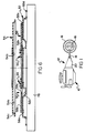
- the motor vehicle driveline seen schematically in Figure 1 includes a prime mover 10 and a transmission 12 having an output shaft 14 drivingly connected to a load such as a ground engaging wheel 16 via a differential gear assembly 18 for rear and/or front axles of a vehicle.
- Prime mover 10 is preferably of the internal, periodic combustion type but may be any type of power plant having torque characteristics that are improved by a torsional vibration damping mechanism.
- Transmission 12 includes a housing 20 containing a plurality of unshown, constant mesh ratio gears or ratio change mechanisms driven by a transmission input shaft or drive 22 partially shown in Figure 2.
- Well-known ratio change devices or clutches within the transmission are employed to selectively (i.e., manually or automatically) put the transmission in a neutral position wherein the input shaft 22 is not connected to the load or in-gear positions wherein the input shaft is connected to the load.
- Clutch plate assembly 24 disposed for rotation about the axis of transmission input shaft 22.
- Clutch plate assembly 24 includes a partially shown annular friction ring 26 in driving relation with shaft 22 via a spring damping mechanism 28 positioned radially between the friction ring and shaft 22 and disposed in parallel with a viscous shear damper mechanism 30.
- the friction ring includes oppositely facing friction surfaces 26a,26b frictionally connectable to a partially shown engine flywheel 32 in response to selective axial movement of an unshown pressure plate in well-known manner.
- the spring damper mechanism 28 which is well-known in the prior art, includes a first set of pairs of springs 34,36 for transmitting full driveline torque, a set of gear anti-rattle springs 38, an intermediate member 40, a hub 42 slidably splined to drive 22, and a support structure including annular side plates 44,46.
- the viscous damper mechanism 30 or module includes annular housing and clutch assemblies 48,50.
- Housing assembly 48 includes first and second radially extending sidewalls 52,54 and clutch assembly 50 includes radially inner and outer members 56,58.
- the sidewalls define an annular radially extending compartment 48a closed at its radially outer extent, open at its radially inner extent and having the clutch assembly inner and outer members disposed therein.
- Support structure is rigidly secured together by a plurality of pins 60.
- the pins also rigidly secure friction ring 26 and viscous damper housing assembly 48 to the support structure.
- the ends of the pins are peened over when assembly is complete.
- Intermediate member 40 includes a plurality of circumferentially spaced apart openings 40a each receiving a pair of springs 34,36.
- the springs are also received by an equal number of pairs of circumferentially spaced apart openings 44a,46a in side plates 44,46. Radially extending ends of openings 40a,44a,46a react against the springs and connect the spring sets in series.
- the viscous damper inner clutch member 56 includes splines 56a which mate with splines 42a of the hub, whereby a given relative rotation between friction ring 26 and hub 42 provides an equal relative rotation between viscous damper housing assembly 48 and inner clutch member 56.
- Housing assembly 48 and clutch assembly 50 define closely spaced apart shear surfaces which are in clutching coaction via viscous shear liquid therebetween.
- the viscous shear liquid is of high viscosity and is preferably a silicone oil, for example dimethyl polysiloxane. The actual viscosity depends on driveline application, area and spacing of the housing and clutch surfaces, mean radius of the surface areas, etc.
- annular housing and clutch assemblies 48,50 are formed of stampings and therefore are relatively inexpensive to manufacture since they require little or no machining. Further, damping mechanism 30 is designed to facilitate installation in a limited available space, rapid and accurate assembly in production, and rapid and accurate filling with viscous shear liquid during assembly.
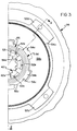
- first sidewall 52 includes a radially outer portion defining a flat, annular shear surface 52a, a radially inner portion defining a flat, annular seal surface 52b, an annular bulge 52c, and a plurality of tabs or feet 52d secured to pins 60 as previously mentioned.
- First sidewall 52 also includes a plurality of axially extending, circumferentially spaced apart tabs or fingers 52e explained further hereinafter.
- Sidewall 54 includes a radially outer portion defining a flat, annular shear surface 54a, a radially inner portion defining a flat, annular seal surface 54b, and an annular axially extending spacer flange 54c sealingly secured to a radially outer extent of shear surface 52a and having an axial length defining the axial distance between shear surfaces 52a,54a.
- outer clutch member 58 includes axially oppositely facing, flat, annular shear surfaces 58a,58b which are closely spaced from the sidewall shear surfaces 52a,54a to form a viscous shear chamber 64, generally bounded in the radial direction by spacer flange 54c and the radially outer periphery of annular bulge 52c.
- the remainder of compartment 48a defines a reservoir chamber 65.
- the inner periphery of outer member 58 is drivingly connected to the outer periphery of inner member 56 via tabs 56b which are received by half of recesses 58c.
- the arcuate length of recesses 58c is greater than that of tabs 56b to allow rotational free play or lost motion therebetween.
- Inner clutch member 56 includes, in addition to splines or tabs 56a,56b, a plurality of arcuate surfaces 56c of equal radius journaling the outer member thereon and a dynamic face seal assembly 66 integral with the inner member.
- the seal assembly is partially shown enlarged in Figure 4.
- Dynamic seal as used herein, means a seal having a portion in sealing relation with a relatively movable surface.
- the seal assembly includes symmetrical face seals 68,70 each having a base portion 68a,70a sealingly affixed to axially oppositely facing surfaces 56d,56e of the inner clutch member, an axially and radially inwardly extending primary seal portion 68b,70b terminating in a lip 68c,70c in dynamic sealing contact with sidewall seal surface 52b,54b, and an axially and radially inwardly extending exclusion seal portion 68d,70d terminating in a lip 68e,70e also in dynamic sealing contact with seal surface 52b,54b.
- seals 68,70 are preferably, but not necessarily, joined by extrusion of the elastomeric material through a plurality of openings 56f in the clutch inner member during the molding process.
- Primary seal portions 68b,70b prevent egress or leakage of fluid from housing compartment 48a of the damper mechanism.
- Exclusion seal portions 68d,70d prevent ingress of abrasive contaminants to the lips of the primary seals when the damper is used in relatively dry environments or of pressurized fluid when the damper is used in, for example, a torque converter housing.
- their axial length is preferably less than that of the primary seals, to reduce seal drag torque and wear.
- Axial separation of the housing sidewalls is prevented and manufacturing tolerances are reduced, particularly in the area of seal surfaces 52b,54b, by structurally connecting the radially inner extent of the sidewalls together by a plurality of circumferentially spaced apart fasteners, fingers or spacers 52e defined by tabs extending axially from sidewall 52 and secured to sidewall 54 by known means such as welding.
- the tabs extend through circumferentially extending openings 53 between splines 42a,56a of hub 42 and inner clutch member 56.
- Figure 5 illustrates an enlarged cross-section of a portion of an alternative molded seal assembly 72 including face seals 74,76 each having extended primary and exclusion seal portions 74a,74b, and 76a,76b to further reduce seal drag torque.
- Molded seal assemblies 66 and 72 simplify assembly of the damper mechanism since they are integral with the clutch assembly and therefore are installed and properly positioned in one operational step with the clutch assembly.
- the molded seal assemblies are also axially compact while still being very flexible in the axial direction; hence, they reduce the axial space necessary to provide reliable sealing while at the same time reducing the effects of manufacturing tolerances which substantially vary seal compression and may dramatically increase seal drag torque.
- the feature of an exclusion seal also protects the primary seal from early or premature failure due to abrasive contaminants.
- FIG. 6 therein is illustrated a method of assembling and rapidly filling damper mechanism 30 with a predetermined volume of silicone oil sufficient to ensure that thermal expansion of the oil does not over fill compartment 48a when the compartment volume is a minimum due to manufacturing tolerances and the oil volume is a maximum due to measuring tolerances, and to ensure a full fill of the shear chamber 64 when the shear volume is a maximum due to manufacturing tolerances and the oil volume is a minimum due to measuring tolerances.
- Assembling and filling include positioning sidewall 52 of housing 48 on a support 78 with shear and seal surfaces 52a,52b facing upward and in a horizontal plane. Clutch assembly 50 is then positioned over sidewall 52 with seal 70 of seal assembly 66 resting on seal surface 52b and outer member shear surface 58a resting on sidewall shear surface 52a, thereby defining a trapped volume excessible via openings 58c between the inner and outer clutch members.
- This trapped volume by design, has a capacity sufficient to receive the above mentioned predetermined volume of silicone oil for all tolerance conditions mentioned above without overflowing the upper surfaces 56d,58b of inner and outer members 56,58.
- the silicone is readily injected into the trapped volume through openings 58c which are not receiving one of the splines or tabs 56b of the inner member.
- Sidewall 54 is then positioned with spacer flange 54c seated on a radially outer extent of shear surface 52a.
- the interface of the spacer flange and shear surface are then sealingly secured together by known methods. Since the silicone oil, contained in the trapped volume, is spaced a substantial distance from spacer flange 54c, any of several rapid welding methods may be used, e.g., resistance or laser welding.
Landscapes
- Engineering & Computer Science (AREA)
- General Engineering & Computer Science (AREA)
- Mechanical Engineering (AREA)
- Physics & Mathematics (AREA)
- Acoustics & Sound (AREA)
- Aviation & Aerospace Engineering (AREA)
- Mechanical Operated Clutches (AREA)
Claims (13)
- Mécanisme de cisaillement visqueux (30) incluant des assemblages de carter et d'embrayage annulaires (48, 50) conçus pour tourner de façon relative autour d'un axe commun ; l'assemblage de carter incluant des première et seconde parois latérales annulaires s'étendant radialement (52, 54) comportant des surfaces de paroi latérale se faisant mutuellement face (52a, 54a) définissant un compartiment annulaire s'étendant radialement (48a) ; un moyen qui assure l'étanchéité et la fixation des parois latérales vis-à-vis de toute rotation relative et de tout déplacement axial au niveau de l'extension radialement externe (54c) du compartiment (48a) ; l'assemblage d'embrayage (50) incluant des parties radialement interne et externe (56, 58), la partie externe (58) comportant des surfaces s'étendant radialement se faisant mutuellement face (58a, 58b) disposées à une faible distance axiale des surfaces de paroi latérale (52a, 54a) en vue d'une co-action d'embrayage visqueux entre elles via un liquide de cisaillement visqueux contenu dans le compartiment, la partie interne (56) s'étendant radialement vers l'intérieur du carter en vue d'une connexion à un moyen d'entraînement (22) ; un moyen d'étanchéité dynamique orienté axialement (66) coopérant entre des parties radialement internes (52b, 54b) des parois latérales (52, 54) et des côtés orientés à l'opposé (56d, 56e) de l'assemblage d'embrayage (50) pour fermer l'extension radialement interne du compartiment (48a),
caractérisé en ce que :
l'assemblage d'embrayage (50) inclut une pluralité d'ouvertures espacées circonférenciellement (53) s'étendant axialement au travers ; et
un moyen (52e) est prévu pour empêcher un déplacement axial relatif des parties radialement internes (52b, 54b) des parois latérales (52, 54), au niveau du moyen (52e) d'empêchement incluant une pluralité de doigts (52e) s'étendant axialement entre les parois latérales (52, 54) et librement au travers des ouvertures d'assemblage d'embrayage (53), les ouvertures (53) présentant des longueurs d'arc permettant une valeur de rotation relative prédéterminée entre l'assemblage d'embrayage (50) et les doigts (52e). - Mécanisme selon la revendication 1, dans lequel les doigts (52e) sont disposés radialement vers l'intérieur du moyen d'étanchéité dynamique (66).
- Mécanisme selon la revendication 1 ou 2, dans lequel les doigts (52e) sont fixés aux parois latérales (52, 54).
- Mécanisme selon la revendication 1 ou 2, dans lequel le moyen d'étanchéité dynamique (66) inclut des première et seconde étanchéités latérales (68, 70) dont chacune comporte une partie de base (68a, 70a) en relation d'étanchéité statique avec l'un des côtés opposés (56d, 56e) de l'assemblage d'embrayage (50) et dont chacune comporte une lèvre (68c, 70c) en relation d'étanchéité dynamique avec la partie radialement interne (52b, 54b) des parois latérales (52, 54).
- Mécanisme selon la revendication 4, dans lequel les première et seconde étanchéités (68, 70) incluent chacune une partie d'étanchéité primaire (68b, 70b) s'étendant axialement en s'éloignant de la partie de base (68a, 70a), s'étendant radialement vers l'extérieur de celle-ci et se terminant selon la lèvre (68c, 70c).
- Mécanisme selon la revendication 5, dans lequel les première et seconde étanchéités (68, 70) incluent chacune une partie d'étanchéité vis-à-vis de corps étrangers (68d, 70d) s'étendant axialement en s'éloignant de la partie de base (68a, 70a), s'étendant radialement vers l'intérieur de celle-ci et se terminant selon une lèvre (68e, 70e) en relation d'étanchéité dynamique avec les parties radialement internes (52b, 54b) des parois latérales (52, 54).
- Mécanisme selon la revendication 1, 2 ou 6, incluant en outre un amortisseur élastique (28) comportant une entrée (60) fixée à l'assemblage de carter annulaire (48) et une sortie (42) connectée au moyen d'entraînement (22) qui est connecté à la partie interne (50) de l'assemblage d'embrayage (56).
- Mécanisme selon la revendication 7, dans lequel l'amortisseur élastique (28) inclut des moyens de ressort relativement raides (34, 36) pour transmettre et atténuer un couple entre l'entrée et la sortie (60, 42) lorsque la sortie (42) est connectée à une charge et des moyens de ressort relativement moins raides (38) disposés en série avec les moyens de ressort raides (34, 36) pour atténuer un couple entre les moyens d'entraînement lorsque la sortie n'est pas connectée à une charge.
- Mécanisme d'amortissement en torsion (24) conçu pour être connecté entre des moyens d'entraînement d'entrée et de sortie (32, 22) d'une transmission transmettant un couple ; le mécanisme comprenant un moyen élastique (28) pour interconnecter par entraînement les moyens d'entraînement et un amortisseur visqueux (30) incluant des assemblages de carter et d'embrayage annulaires (48, 50) conçus pour tourner autour d'un axe de rotation de l'un des moyens d'entraînement ; l'assemblage de carter (48) incluant des première et seconde parois latérales s'étendant radialement (52, 54) comportant des surfaces de paroi latérale se faisant mutuellement face (52a, 54a) définissant un compartiment annulaire s'étendant radialement (48a) comportant une extension ouverte radialement interne et fermée au niveau de son extension radialement externe au moyen d'une fixation étanche des parois latérales ensemble, le carter (48) étant conçu pour être entraîné par l'un des moyens d'entraînement (32) ; l'assemblage d'embrayage (50) incluant des parties radialement externe et interne (58, 56), la partie externe (58) comportant des surfaces s'étendant radialement orientées à l'opposé (58a, 58b) disposées à une courte distance axiale des surfaces de paroi latérale (52a, 54a) en vue d'une coaction d'embrayage visqueux avec via un liquide de cisaillement visqueux contenu dans le compartiment, la partie interne (56) s'étendant radialement vers l'intérieur du carter (48) pour assurer une connexion par entraînement sur l'autre moyen d'entraînement ; un moyen d'étanchéité dynamique (66) coopérant entre la partie interne d'embrayage (56) et des parties radialement internes (52b, 54b) des parois latérales de carter (52, 54) pour assurer l'étanchéité de l'extension radialement interne du compartiment,
caractérisé par :
l'assemblage d'embrayage (50) inclut une pluralité d'ouvertures espacées circonférenciellement (53) s'étendant au travers ; et
l'assemblage de carter (48) inclut une pluralité de dispositifs de fixation (52e) s'étendant librement au travers desdites ouvertures (53) et comportant des extrémités opposées fixées aux parois latérales de carter (52, 54) pour empêcher un déplacement axial des parois latérales (52, 54) l'une par rapport à l'autre, les ouvertures espacées circonférenciellement (53) présentant une longueur d'arc permettant une valeur prédéterminée de rotation relative entre les assemblages de carter et d'embrayage (48, 50). - Mécanisme selon la revendication 9, dans lequel lesdites ouvertures (53) et lesdits dispositifs de fixation (52e) sont positionnés entre le moyen d'étanchéité (66) et l'extension radialement interne de la partie interne d'assemblage d'embrayage (56).
- Mécanisme selon la revendication 9, dans lequel les première et seconde parois latérales (52, 54) de l'assemblage de carter (48) comportent chacune une surface d'étanchéité s'étendant radialement (52b, 54b) orientée axialement et espacée de surfaces orientées à l'opposé (56c, 56d) de la partie interne d'embrayage (56) ; et
une étanchéité latérale (68, 70) formée en un matériau élastomérique moulé sur chaque surface orientée à l'opposé (56c, 56d) de la partie interne d'assemblage d'embrayage (56), chaque étanchéité (68, 70) comportant une partie d'étanchéité primaire (68b, 70b) s'étendant axialement en s'éloignant de la partie de base (68a, 70a), s'étendant radialement vers l'extérieur de celle-ci et se terminant selon une lèvre (68c, 70c) selon une relation d'étanchéité dynamique avec la surface d'étanchéité de paroi latérale associée (52b, 54b). - Mécanisme selon la revendication 11, dans lequel chaque étanchéité moulée (68, 70) inclut également une partie d'étanchéité vis-à-vis de corps étrangers (68d, 70d) s'étendant axialement en s'éloignant de la partie de base (68a, 70a), s'étendant radialement vers l'intérieur de celle-ci et se terminant selon une lèvre (68e, 70e) selon une relation d'étanchéité dynamique avec la surface d'étanchéité de paroi latérale associée (52b, 54b).
- Mécanisme selon la revendication 12, dans lequel les surfaces orientées à l'opposé (56c, 56d) de la partie interne (56) incluent une pluralité d'ouvertures espacées circonférenciellement (56f) les traversant pour joindre les bases des étanchéités via un matériau élastomérique extrudé dans les ouvertures (56f) pendant un moulage des étanchéités.
Applications Claiming Priority (2)
| Application Number | Priority Date | Filing Date | Title |
|---|---|---|---|
| US257258 | 1988-10-12 | ||
| US07/257,258 US4936434A (en) | 1988-10-12 | 1988-10-12 | Viscous damper with means preventing sidewall deflection |
Publications (3)
| Publication Number | Publication Date |
|---|---|
| EP0364221A2 EP0364221A2 (fr) | 1990-04-18 |
| EP0364221A3 EP0364221A3 (fr) | 1991-10-02 |
| EP0364221B1 true EP0364221B1 (fr) | 1994-05-11 |
Family
ID=22975533
Family Applications (1)
| Application Number | Title | Priority Date | Filing Date |
|---|---|---|---|
| EP89310365A Expired - Lifetime EP0364221B1 (fr) | 1988-10-12 | 1989-10-11 | Amortisseur visqueux avec moyen de prévention de la déflexion des parois |
Country Status (5)
| Country | Link |
|---|---|
| US (1) | US4936434A (fr) |
| EP (1) | EP0364221B1 (fr) |
| JP (1) | JPH02129411A (fr) |
| KR (1) | KR940010681B1 (fr) |
| DE (1) | DE68915244T2 (fr) |
Families Citing this family (8)
| Publication number | Priority date | Publication date | Assignee | Title |
|---|---|---|---|---|
| US5172796A (en) * | 1992-03-18 | 1992-12-22 | Eaton Corporation | Reduced cost viscous coupling by-pass element for a torque converter |
| US5362276A (en) * | 1992-09-02 | 1994-11-08 | General Motors Corporation | Selective torque clipping mechanism |
| DE4413998B4 (de) * | 1994-04-22 | 2005-03-24 | Zf Sachs Ag | Schwungradvorrichtung |
| JPH08320029A (ja) * | 1995-05-26 | 1996-12-03 | Exedy Corp | ダンパーディスク組立体 |
| US5603660A (en) * | 1995-05-31 | 1997-02-18 | Eaton Corporation | Viscous damper and shear plate for improved fluid flow |
| DE19648049C2 (de) * | 1996-11-20 | 2003-06-12 | Zf Sachs Ag | Drehschwingungsdämpfer |
| US7341523B2 (en) * | 1999-06-04 | 2008-03-11 | Rohs-Voigt Patentverwertungsgesellschaft Mbh | Torsional vibration damper |
| KR20030030464A (ko) * | 2001-10-11 | 2003-04-18 | 현대자동차주식회사 | 자동변속기의 윤활장치 |
Citations (1)
| Publication number | Priority date | Publication date | Assignee | Title |
|---|---|---|---|---|
| EP0174233A1 (fr) * | 1984-08-03 | 1986-03-12 | Valeo | Dispositif amortisseur de torsion à grand débattement angulaire, en particulier friction d'embrayage, notamment pour véhicule automobile |
Family Cites Families (9)
| Publication number | Priority date | Publication date | Assignee | Title |
|---|---|---|---|---|
| US2316820A (en) * | 1940-11-25 | 1943-04-20 | Thelander W Vincent | Clutch plate |
| US2513379A (en) * | 1944-09-28 | 1950-07-04 | Dana Corp | Friction clutch plate |
| US4601676A (en) * | 1982-09-16 | 1986-07-22 | Kabushiki Kaisha Daikin Seisakusho | Damper disc |
| US4790792A (en) * | 1983-12-22 | 1988-12-13 | Eaton Corporation | Torsion damping assembly |
| US4614175A (en) * | 1983-12-27 | 1986-09-30 | Mitsubishi Denki Kabushiki Kaisha | Engine exhaust gas recirculation control system |
| DE3645392B4 (de) * | 1985-09-07 | 2009-11-26 | Luk Lamellen Und Kupplungsbau Beteiligungs Kg | Drehstoßmindernde Einrichtung |
| US4782932A (en) * | 1985-11-01 | 1988-11-08 | Eaton Corporation | Torsion damping mechanism |
| EP0238235A3 (fr) * | 1986-03-21 | 1989-01-25 | Eaton Corporation | Amortisseur de torsion |
| US7342277B2 (en) * | 2005-11-21 | 2008-03-11 | Intel Corporation | Transistor for non volatile memory devices having a carbon nanotube channel and electrically floating quantum dots in its gate dielectric |
-
1988
- 1988-10-12 US US07/257,258 patent/US4936434A/en not_active Expired - Lifetime
-
1989
- 1989-10-11 EP EP89310365A patent/EP0364221B1/fr not_active Expired - Lifetime
- 1989-10-11 DE DE68915244T patent/DE68915244T2/de not_active Expired - Fee Related
- 1989-10-12 JP JP1266081A patent/JPH02129411A/ja active Pending
- 1989-10-12 KR KR1019890014625A patent/KR940010681B1/ko not_active Expired - Fee Related
Patent Citations (1)
| Publication number | Priority date | Publication date | Assignee | Title |
|---|---|---|---|---|
| EP0174233A1 (fr) * | 1984-08-03 | 1986-03-12 | Valeo | Dispositif amortisseur de torsion à grand débattement angulaire, en particulier friction d'embrayage, notamment pour véhicule automobile |
Also Published As
| Publication number | Publication date |
|---|---|
| US4936434A (en) | 1990-06-26 |
| DE68915244D1 (de) | 1994-06-16 |
| EP0364221A2 (fr) | 1990-04-18 |
| JPH02129411A (ja) | 1990-05-17 |
| EP0364221A3 (fr) | 1991-10-02 |
| KR900006163A (ko) | 1990-05-07 |
| KR940010681B1 (ko) | 1994-10-24 |
| DE68915244T2 (de) | 1994-12-08 |
Similar Documents
| Publication | Publication Date | Title |
|---|---|---|
| US4782936A (en) | Two mass flywheel assembly with torsional damping means | |
| EP0294049B1 (fr) | Volant d'inertie en deux parties avec dispositif d'amortissement visqueux | |
| EP0340608B1 (fr) | Variateur continu de vitesse et amortisseur de torsion à grand débattement | |
| EP0304169B1 (fr) | Mécanisme d'amortissement de vibrations de torsion | |
| EP0364219B1 (fr) | Procédé pour la fabrication, l'assemblage et le remplissage d'un amortisseur visqueux | |
| US5353664A (en) | Torsional vibration damping device | |
| EP0364223B1 (fr) | Amortisseur visqueux avec joint d'étanchéité dynamique monté | |
| US4936434A (en) | Viscous damper with means preventing sidewall deflection | |
| GB2231123A (en) | Torsion damping device with a dynamic vibration damper, in particular for automotive vehicles | |
| EP0419887B1 (fr) | Amortisseur visqueux avec joint d'étanchéité à basse transmission de couple | |
| EP0238235A2 (fr) | Amortisseur de torsion | |
| EP0304159B1 (fr) | Unité d'amortissement visqueux pour mécanisme d'amortissement de vibration de torsion | |
| EP0294130A2 (fr) | Volant d'inertie en deux parties avec commande de rotation relative | |
| JPS6151171B2 (fr) | ||
| US5603660A (en) | Viscous damper and shear plate for improved fluid flow | |
| JPH0949531A (ja) | 粘性抵抗発生機構 | |
| EP0469364B1 (fr) | Procédé pour fabriquer et pour la mise sous tension de ressort en matières composites | |
| JP2676997B2 (ja) | ロックアップクラッチ付き流体伝動装置のダンパ機構 | |
| JP3429526B2 (ja) | フライホイール組立体 | |
| EP0469366A2 (fr) | Amortisseur de vibrations tortionnelles à ressorts en matières composites | |
| JPH0349304Y2 (fr) | ||
| JPH04211746A (ja) | 自動変速機の動力伝達装置 | |
| JPH109340A (ja) | ダンパー機構 | |
| JPH09303484A (ja) | 曲がり板ばね及びダンパー機構 |
Legal Events
| Date | Code | Title | Description |
|---|---|---|---|
| PUAI | Public reference made under article 153(3) epc to a published international application that has entered the european phase |
Free format text: ORIGINAL CODE: 0009012 |
|
| AK | Designated contracting states |
Kind code of ref document: A2 Designated state(s): DE FR GB IT |
|
| PUAL | Search report despatched |
Free format text: ORIGINAL CODE: 0009013 |
|
| AK | Designated contracting states |
Kind code of ref document: A3 Designated state(s): DE FR GB IT |
|
| 17P | Request for examination filed |
Effective date: 19911231 |
|
| 17Q | First examination report despatched |
Effective date: 19930816 |
|
| GRAA | (expected) grant |
Free format text: ORIGINAL CODE: 0009210 |
|
| AK | Designated contracting states |
Kind code of ref document: B1 Designated state(s): DE FR GB IT |
|
| REF | Corresponds to: |
Ref document number: 68915244 Country of ref document: DE Date of ref document: 19940616 |
|
| ITF | It: translation for a ep patent filed | ||
| ET | Fr: translation filed | ||
| PLBE | No opposition filed within time limit |
Free format text: ORIGINAL CODE: 0009261 |
|
| STAA | Information on the status of an ep patent application or granted ep patent |
Free format text: STATUS: NO OPPOSITION FILED WITHIN TIME LIMIT |
|
| 26N | No opposition filed | ||
| PGFP | Annual fee paid to national office [announced via postgrant information from national office to epo] |
Ref country code: GB Payment date: 19970917 Year of fee payment: 9 |
|
| PGFP | Annual fee paid to national office [announced via postgrant information from national office to epo] |
Ref country code: FR Payment date: 19971007 Year of fee payment: 9 |
|
| PGFP | Annual fee paid to national office [announced via postgrant information from national office to epo] |
Ref country code: DE Payment date: 19971030 Year of fee payment: 9 |
|
| PG25 | Lapsed in a contracting state [announced via postgrant information from national office to epo] |
Ref country code: GB Free format text: LAPSE BECAUSE OF NON-PAYMENT OF DUE FEES Effective date: 19981011 |
|
| GBPC | Gb: european patent ceased through non-payment of renewal fee |
Effective date: 19981011 |
|
| PG25 | Lapsed in a contracting state [announced via postgrant information from national office to epo] |
Ref country code: FR Free format text: LAPSE BECAUSE OF NON-PAYMENT OF DUE FEES Effective date: 19990630 |
|
| REG | Reference to a national code |
Ref country code: FR Ref legal event code: ST |
|
| PG25 | Lapsed in a contracting state [announced via postgrant information from national office to epo] |
Ref country code: DE Free format text: LAPSE BECAUSE OF NON-PAYMENT OF DUE FEES Effective date: 19990803 |
|
| PG25 | Lapsed in a contracting state [announced via postgrant information from national office to epo] |
Ref country code: IT Free format text: LAPSE BECAUSE OF NON-PAYMENT OF DUE FEES;WARNING: LAPSES OF ITALIAN PATENTS WITH EFFECTIVE DATE BEFORE 2007 MAY HAVE OCCURRED AT ANY TIME BEFORE 2007. THE CORRECT EFFECTIVE DATE MAY BE DIFFERENT FROM THE ONE RECORDED. Effective date: 20051011 |