EP0364242A2 - Caisse de tête - Google Patents
Caisse de tête Download PDFInfo
- Publication number
- EP0364242A2 EP0364242A2 EP89310400A EP89310400A EP0364242A2 EP 0364242 A2 EP0364242 A2 EP 0364242A2 EP 89310400 A EP89310400 A EP 89310400A EP 89310400 A EP89310400 A EP 89310400A EP 0364242 A2 EP0364242 A2 EP 0364242A2
- Authority
- EP
- European Patent Office
- Prior art keywords
- fiber suspension
- headbox
- conduit
- inlet
- passage
- Prior art date
- Legal status (The legal status is an assumption and is not a legal conclusion. Google has not performed a legal analysis and makes no representation as to the accuracy of the status listed.)
- Ceased
Links
- 239000000835 fiber Substances 0.000 claims abstract description 66
- 239000000725 suspension Substances 0.000 claims abstract description 63
- 239000012530 fluid Substances 0.000 claims abstract description 22
- 230000007704 transition Effects 0.000 claims abstract description 16
- 230000003467 diminishing effect Effects 0.000 claims description 3
- 230000000694 effects Effects 0.000 description 4
- 238000009826 distribution Methods 0.000 description 3
- 238000004519 manufacturing process Methods 0.000 description 2
- 238000003466 welding Methods 0.000 description 2
- 238000007599 discharging Methods 0.000 description 1
- 239000006185 dispersion Substances 0.000 description 1
- 239000012467 final product Substances 0.000 description 1
- 239000007769 metal material Substances 0.000 description 1
- 238000009827 uniform distribution Methods 0.000 description 1
Images


Classifications
-
- D—TEXTILES; PAPER
- D21—PAPER-MAKING; PRODUCTION OF CELLULOSE
- D21F—PAPER-MAKING MACHINES; METHODS OF PRODUCING PAPER THEREON
- D21F1/00—Wet end of machines for making continuous webs of paper
- D21F1/02—Head boxes of Fourdrinier machines
- D21F1/026—Details of the turbulence section
-
- D—TEXTILES; PAPER
- D21—PAPER-MAKING; PRODUCTION OF CELLULOSE
- D21F—PAPER-MAKING MACHINES; METHODS OF PRODUCING PAPER THEREON
- D21F1/00—Wet end of machines for making continuous webs of paper
- D21F1/02—Head boxes of Fourdrinier machines
Definitions
- the present invention relates to the general field of paper-making equipment and more particularly, to a novel headbox with a diffuser to improve the dispersion of fibers throughout the suspension.
- an object of this invention is an improved headbox with superior fiber distribution characteristics and yet which is simple and inexpensive to manufacture.
- the headbox comprises a diffuser mounted between the inlet and the outlet chambers of the headbox.
- the diffuser includes a cluster of conduits, each being divided into at least two successive portions of larger cross-sectional area, namely a first portion and a second portion, the second portion being located downstream respectively to the first portion.
- an elongated stem that defines with an inner wall of the conduit a passage for conveying fiber suspension, the passage, in cross-section, having the shape of a multiply connected domain, such as an annulus.
- the transition between the first and second portions is abrupt to create vortices in the flow of the fiber suspension.
- the multiply connected domain passage allows to obtain an increased contact surface between the fiber suspension and the conduit comparatively to a cylindrical passage, thus increasing the shear forces in the fiber suspension.
- the abrupt transition permits to establish and maintain a controlled level of turbulence. Both factors contribute to break and disperse flocs present in the fibers suspension.
- a stem is provided only in the first portion of the conduit, however, it may be envisaged to construct the stem as a stepped structure of diminishing cross-sectional area in the direction of the fiber suspension flow to define in the conduit a plurality of multiply connected domain passages of increasing dimension.
- each conduit of the diffuser with a channel including an inlet portion in fluid communication with the inlet chamber of the headbox, the channel further comprising two or more branches leading from the inlet portion to the fiber suspension passage in the conduit.
- This arrangement further promotes a turbulent flow because the flow of fiber suspension is split in two or more, and forced to effect a series of sharp bends before entering the fiber suspension passage in the conduit.
- the present invention comprises, in general terms, a headbox including: - an inlet chamber communicating with a supply of fiber suspension; - an outlet chamber located downstream of the inlet chamber and comprising a discharge opening; and - a diffuser mounted between the inlet and the outlet chambers to establish a fluid path from the inlet chamber to the outlet chamber, the diffuser including a plurality of conduits in fluid communication with the inlet and outlet chambers, each conduit being divided in at least two successive portions, establishing respective passages to convey fiber suspension of increasing cross-sectional area in the direction of flow of fiber suspension through the conduits, an elongated stem received in the conduit, one of the passages being defined between the stem and an inner wall of the conduit, the passage defining in cross-section a multiply connected domain.
- the invention also extends to a headbox comprising: - an inlet chamber communicating with a supply of fiber suspension; - an outlet chamber downstream of the inlet chamber and comprising a discharge opening; and - a diffuser mounted between the inlet and the outlet chambers to establish a fluid path from the inlet chamber to the outlet chamber, the diffuser including a cluster of conduits, in fluid communication with the inlet and outlet chambers, each conduit being divided in at least two successive portions, establishing respective fiber suspension passages of increasing cross-sectional area in the direction of fiber suspension flow through the conduit, at least one of the passages defining in cross-section a multiply connected domain.
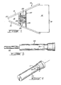
- the reference numeral 10 designates in general a headbox shown in cross-section that is used to continuously supply fiber suspension to a foraminous carrier of a paper machine.
- the headbox 10 comprises a pair of converging top and bottom walls 12 and 14 respectively, constructed from metallic plates. At one end, the plates 12 and 14 define an inlet chamber 16 closed by a wall 19. The inlet chamber 16 is connected to a suitable supply of fiber suspension.
- the plates 12 and 14 define an outlet chamber 18 which is generally triangular in cross-section.
- the outlet chamber 18 is provided with a slice opening 20 for discharging fiber suspension, extending the entire width of the headbox 10 and being defined between the extremities of the plates 12 and 14.
- the diffuser 22 comprises a pair of parallel metallic plates 24 and 26 extending the entire width of the headbox 10 and being secured to the plates 12 and 14 by welding or by any other appropriate means.
- the plates 24 and 26 constitute a support for a cluster of tubes 28 which may or may not be parallel, defining fiber suspension passages between the inlet and the outlet chambers 16 and 18 respectively.
- each tube 28 is of a generally constant cross-section throughout the length thereof except at the extremity thereof extending in the outlet chamber 18 which is slightly enlarged.
- the tube 28 is made of metallic material and it is secured in respective bores provided in the plates 24 and 26 by welding or by any other appropriate means.
- the extremity of the tube 28 received in the plate 24 is slightly recessed to define a seat 30.
- a metallic stem 32 having at one end an annular ridge 34 secured in the seat 30. Downstream of the annular ridge 34, the radius of the stem 32 is reduced by an amount corresponding generally to the wall thickness of the tube 28 to provide a circular portion 36 received within the conduit 28 and sealingly engaging the inner wall thereof.
- the stem diameter is reduced once again to define between the outer surface of the stem 32 and the inner wall of the conduit 28, in cross-section, a passage 38 for conveying fiber suspension, shaped as an annulus or, more generally stated, defining a multiply connected domain.
- a domain is simply connected if it has no "holes". More precisely, a domain is simply connected if, for every simple closed curve in the domain, the region encompassed by the curve lies wholly in the domain. A simply connected domain is shown in Figure 8.
- Examples of simply connected domains are the following: the interior of a circle, the interior of a square, a sector, a quadrant, the whole xy plane.
- the annular region between two circles is not simply connected, nor is the interior of a circle minus the center point.
- the passage 38 communicates with the inlet chamber 16 through a channel structure 39 including an inlet portion constituted by a straight centrally located and longitudinally extending bore 40 opening in the inlet chamber 16 and extending slightly beyond the circular portion 36 to unite with a cross bore 42 communicating with the passage 38.
- the channel structure 39 which is somewhat T shaped as best shown in Figure 4, has the effect of splitting in two the flow of fiber suspension and subjecting the flow to two 90° bends to augment the turbulence for better uniformity of the fiber distribution in the suspension.
- the centrally located bore 40 communicates with the passage 38 by two generally oppositely extending passages 100, each passage 100 defining an obtuse angle with the axis of the stem 32. Stated otherwise, the passages 100 force the flow of fiber suspension to effect a bend in excess of 90° when leaving the central conduit 40.
- the centrally located bore 40 leads to a chamber 200 communicating with the passage 38 through four passages 202 parallel with the central conduit 40.
- the central conduit 40, the chamber 200 and the passages 202 force the flow of fiber suspension to effect two 180 degrees bends before reaching the passage 38.
- the length of the stem 32 is somewhat shorter than the overall length of the tube 28 to divide the tube in two portions, namely a first portion 44 and a second portion 46 which are separated by an imaginary plane tangent to the free end of the stem 32 and being identified by the dotted line 48.
- the second portion 46 defines a cylindrical fiber suspension passage of larger cross-sectional area than the ring shaped passage 38 of the first portion 44, the first and second passages being separated by an abrupt transition produced by the sudden termination of the stem 32. The abrupt transition contributes to create vortices in the fiber suspension flow to establish and maintain a controlled level of turbulence. It will be appreciated that the portions 44 and 46 are free of restrictions.
- the stem 32 has a stepped structure creating in the tube 28 three successive passages of larger cross-sectional area separated by abrupt transitions, namely two adjacent ring-shaped passages followed by a cylindrical passage.
- the stem of three or more serially connected sections providing the desired number of ring-shaped passsages in the tube 28.
- the dimensions of the various elements of the tube 28 and of the stem 32 are selected according to the desired flow characteristics.
Landscapes
- Paper (AREA)
Applications Claiming Priority (2)
| Application Number | Priority Date | Filing Date | Title |
|---|---|---|---|
| CA000579854A CA1320860C (fr) | 1988-10-12 | 1988-10-12 | Caisse de tete |
| CA579854 | 1988-10-12 |
Publications (2)
| Publication Number | Publication Date |
|---|---|
| EP0364242A2 true EP0364242A2 (fr) | 1990-04-18 |
| EP0364242A3 EP0364242A3 (fr) | 1991-04-24 |
Family
ID=4138892
Family Applications (1)
| Application Number | Title | Priority Date | Filing Date |
|---|---|---|---|
| EP19890310400 Ceased EP0364242A3 (fr) | 1988-10-12 | 1989-10-11 | Caisse de tête |
Country Status (2)
| Country | Link |
|---|---|
| EP (1) | EP0364242A3 (fr) |
| CA (1) | CA1320860C (fr) |
Cited By (5)
| Publication number | Priority date | Publication date | Assignee | Title |
|---|---|---|---|---|
| US5876564A (en) * | 1995-10-20 | 1999-03-02 | Institute Of Paper Science And Technology, Inc. | Methods and apparatus to enhance paper and board forming qualities |
| US6153057A (en) * | 1995-10-20 | 2000-11-28 | Institute Of Paper Science And Technology, Inc. | Methods and apparatus to enhance paper and board forming qualities |
| US6368460B1 (en) | 1995-10-20 | 2002-04-09 | Institute Of Paper Science And Technology, Inc. | Method and apparatus to enhance paper and board forming qualities |
| US6406595B1 (en) | 1995-10-20 | 2002-06-18 | Institute Of Paper Science And Technology, Inc. | Methods and apparatus to enhance paper and board forming qualities |
| US6425984B2 (en) | 1995-10-20 | 2002-07-30 | Institute Of Paper Science And Technology, Inc. | Layered fiber structure in paper products |
Family Cites Families (6)
| Publication number | Priority date | Publication date | Assignee | Title |
|---|---|---|---|---|
| US2970644A (en) * | 1958-06-02 | 1961-02-07 | Webster David Richan | Liquid dispersion conduit |
| US3296066A (en) * | 1963-11-13 | 1967-01-03 | Black Clawson Co | Headbox for papermaking machine and stock distributor thereto |
| DE1561697A1 (de) * | 1967-04-15 | 1970-10-01 | Voith Gmbh J M | Verfahren zum kontinuierlichen Verduennen und/oder Mischen von langen,zum Verspinnen neigende Fasern enthaltenen Suspensionen und Vorrichtung zum Durchfuehren dieses Verfahrens |
| SE355615B (fr) * | 1970-06-15 | 1973-04-30 | Ahlstroem Oy | |
| JPH0670314B2 (ja) * | 1984-04-03 | 1994-09-07 | シユトーラ フエルトミユ−レ アクチエンゲゼルシヤフト | 繊維懸濁液の脱インキ処理用浮選装置 |
| AT384633B (de) * | 1986-05-12 | 1987-12-10 | Albert Hans | Stoffauflauf fuer papiermaschinen |
-
1988
- 1988-10-12 CA CA000579854A patent/CA1320860C/fr not_active Expired - Fee Related
-
1989
- 1989-10-11 EP EP19890310400 patent/EP0364242A3/fr not_active Ceased
Cited By (5)
| Publication number | Priority date | Publication date | Assignee | Title |
|---|---|---|---|---|
| US5876564A (en) * | 1995-10-20 | 1999-03-02 | Institute Of Paper Science And Technology, Inc. | Methods and apparatus to enhance paper and board forming qualities |
| US6153057A (en) * | 1995-10-20 | 2000-11-28 | Institute Of Paper Science And Technology, Inc. | Methods and apparatus to enhance paper and board forming qualities |
| US6368460B1 (en) | 1995-10-20 | 2002-04-09 | Institute Of Paper Science And Technology, Inc. | Method and apparatus to enhance paper and board forming qualities |
| US6406595B1 (en) | 1995-10-20 | 2002-06-18 | Institute Of Paper Science And Technology, Inc. | Methods and apparatus to enhance paper and board forming qualities |
| US6425984B2 (en) | 1995-10-20 | 2002-07-30 | Institute Of Paper Science And Technology, Inc. | Layered fiber structure in paper products |
Also Published As
| Publication number | Publication date |
|---|---|
| EP0364242A3 (fr) | 1991-04-24 |
| CA1320860C (fr) | 1993-08-03 |
Similar Documents
| Publication | Publication Date | Title |
|---|---|---|
| US5465848A (en) | Flotation cell and injector | |
| US5019215A (en) | Headbox with conduits having multiply connected domains | |
| FI110700B (fi) | Perälaatikon putkipatterilaite | |
| US4512888A (en) | Apparatus for removal by flotation of solid particles from liquid | |
| US8303774B2 (en) | Headbox for a machine for producing a fibrous web | |
| US8221590B2 (en) | Headbox for a machine for producing a fibrous web | |
| US3802966A (en) | Apparatus for delivering a fluid suspension to a forming unit clear reactor power plant | |
| US5626722A (en) | Headbox of a paper/board machine | |
| US8236137B2 (en) | Headbox for a machine for producing a fibrous web | |
| US6334579B1 (en) | Air atomizing nozzle | |
| EP1520072B2 (fr) | Appareil classeur a plusieurs etages et panier classeur pour classer des suspensions de pate | |
| EP0769586B1 (fr) | Procédé et dispositif pour l'amélioration des qualités de formage d'un papier ou carton | |
| US5259512A (en) | Screen for pressure sorters for fiber suspensions | |
| FI111740B (fi) | Paperikoneen perälaatikon aallotettu huullesarja | |
| US3945882A (en) | Stock inlet arrangement for a paper-making machine | |
| CA1320860C (fr) | Caisse de tete | |
| US3652392A (en) | Contracting pre-slice flow distributor for papermaking machine headbox | |
| US4897160A (en) | Head box for a paper making machine | |
| US4221635A (en) | Pulp feed for a papermaking machine | |
| US6099692A (en) | Headbox turbulence generator | |
| US4432835A (en) | Method and an apparatus for the feeding of a fibre suspension onto the wire of a web former | |
| US4298429A (en) | Means for effecting cross direction fiber orientation in a papermaking machine headbox | |
| CN102822417B (zh) | 流浆箱和带有流浆箱的成页单元 | |
| US6148861A (en) | Multiway valve for fluids and its use | |
| EP0166669B1 (fr) | Système diffuseur pour pâte à papier |
Legal Events
| Date | Code | Title | Description |
|---|---|---|---|
| PUAI | Public reference made under article 153(3) epc to a published international application that has entered the european phase |
Free format text: ORIGINAL CODE: 0009012 |
|
| AK | Designated contracting states |
Kind code of ref document: A2 Designated state(s): DE FR GB IT SE |
|
| PUAL | Search report despatched |
Free format text: ORIGINAL CODE: 0009013 |
|
| AK | Designated contracting states |
Kind code of ref document: A3 Designated state(s): DE FR GB IT SE |
|
| 17P | Request for examination filed |
Effective date: 19911004 |
|
| 17Q | First examination report despatched |
Effective date: 19931105 |
|
| STAA | Information on the status of an ep patent application or granted ep patent |
Free format text: STATUS: THE APPLICATION HAS BEEN REFUSED |
|
| 18R | Application refused |
Effective date: 19941204 |