EP0364380A1 - Anschlusssystem, insbesondere für unter hohem Druck stehende hydraulische Leitung - Google Patents
Anschlusssystem, insbesondere für unter hohem Druck stehende hydraulische Leitung Download PDFInfo
- Publication number
- EP0364380A1 EP0364380A1 EP89440109A EP89440109A EP0364380A1 EP 0364380 A1 EP0364380 A1 EP 0364380A1 EP 89440109 A EP89440109 A EP 89440109A EP 89440109 A EP89440109 A EP 89440109A EP 0364380 A1 EP0364380 A1 EP 0364380A1
- Authority
- EP
- European Patent Office
- Prior art keywords
- tube
- retaining ring
- well
- beams
- sleeve
- Prior art date
- Legal status (The legal status is an assumption and is not a legal conclusion. Google has not performed a legal analysis and makes no representation as to the accuracy of the status listed.)
- Granted
Links
- 230000008878 coupling Effects 0.000 title abstract description 7
- 238000010168 coupling process Methods 0.000 title abstract description 7
- 238000005859 coupling reaction Methods 0.000 title abstract description 7
- 239000011324 bead Substances 0.000 claims abstract description 28
- 230000002093 peripheral effect Effects 0.000 claims abstract description 27
- 210000002105 tongue Anatomy 0.000 claims description 16
- 238000006073 displacement reaction Methods 0.000 claims description 3
- 239000002184 metal Substances 0.000 claims description 3
- 238000007789 sealing Methods 0.000 claims description 3
- 230000015572 biosynthetic process Effects 0.000 claims 1
- 230000000694 effects Effects 0.000 description 9
- 238000000034 method Methods 0.000 description 9
- 239000012530 fluid Substances 0.000 description 5
- 230000000903 blocking effect Effects 0.000 description 4
- 238000001125 extrusion Methods 0.000 description 2
- 238000004519 manufacturing process Methods 0.000 description 2
- 238000000465 moulding Methods 0.000 description 2
- 229920002994 synthetic fiber Polymers 0.000 description 2
- 240000008042 Zea mays Species 0.000 description 1
- 230000006835 compression Effects 0.000 description 1
- 238000007906 compression Methods 0.000 description 1
- 238000010276 construction Methods 0.000 description 1
- 230000006378 damage Effects 0.000 description 1
- 230000007423 decrease Effects 0.000 description 1
- 238000009434 installation Methods 0.000 description 1
- 239000000463 material Substances 0.000 description 1
- 210000000056 organ Anatomy 0.000 description 1
- 238000010079 rubber tapping Methods 0.000 description 1
- 229920001169 thermoplastic Polymers 0.000 description 1
- 239000004416 thermosoftening plastic Substances 0.000 description 1
Images

Classifications
-
- F—MECHANICAL ENGINEERING; LIGHTING; HEATING; WEAPONS; BLASTING
- F16—ENGINEERING ELEMENTS AND UNITS; GENERAL MEASURES FOR PRODUCING AND MAINTAINING EFFECTIVE FUNCTIONING OF MACHINES OR INSTALLATIONS; THERMAL INSULATION IN GENERAL
- F16L—PIPES; JOINTS OR FITTINGS FOR PIPES; SUPPORTS FOR PIPES, CABLES OR PROTECTIVE TUBING; MEANS FOR THERMAL INSULATION IN GENERAL
- F16L37/00—Couplings of the quick-acting type
- F16L37/08—Couplings of the quick-acting type in which the connection between abutting or axially overlapping ends is maintained by locking members
- F16L37/084—Couplings of the quick-acting type in which the connection between abutting or axially overlapping ends is maintained by locking members combined with automatic locking
- F16L37/098—Couplings of the quick-acting type in which the connection between abutting or axially overlapping ends is maintained by locking members combined with automatic locking by means of flexible hooks
- F16L37/0982—Couplings of the quick-acting type in which the connection between abutting or axially overlapping ends is maintained by locking members combined with automatic locking by means of flexible hooks with a separate member for releasing the coupling
Definitions
- the invention relates to a connector for flexible pipe or rigid pipe, in particular, of a high pressure hydraulic circuit, comprising, on the one hand, a female part into which is introduced the free end of a tube to be connected, this female part being formed by a decomposing well, starting from the bottom, into a cylindrical bore of diameter, at least equal to the external diameter of the tube to be connected, a housing and a constriction defining with this latter a shoulder and, on the other hand, means of snap lock constituting retractable steps interposed between the shoulder arranged in said well and, the rear face, a peripheral bead fitted to the tube to be connected, to prevent it from escaping from said female part.
- the present invention will find its application in any installation through which a fluid is subjected or not subjected to high pressures, and, more particularly, in the industry specialized in the field of hydraulics.
- the most frequently used fittings for connecting pipes in which a fluid is conveyed, in particular under high pressure consist, on the one hand, of a female part comprising a threaded bore into which the free end is introduced. of the tube to be connected.
- said connector comprises a male part in the form of a sleeve fitted on said tube and comprising, on its outer periphery, a thread intended to cooperate with the tapping arranged in the bore of said female part. More precisely, this male part is engaged on the tube, at the rear of a peripheral bead, so that after screwing and tightening in the female part, it comes to immobilize the tube in the latter by action on the rear face of said peripheral bead.
- robotic assembly requires compliance with certain conditions.
- connection of the parts to be assembled must be easy to perform without requiring specific dexterity.
- gripping members of automatic machines called robots, are only capable of performing very simple gestures and of limited amplitude.
- gripping members are able to move, without great difficulty, by translation to go from one point to another, the angular displacement that it is possible to print them remains, however, reduced.
- pneumatic means to generate a constant rotational movement corresponding, for example, to a screwing action.
- the part to be assembled must be easily accessible because of the space which, generally, these gripping members of said robots present.
- the male part is in the form of a tubular end piece comprising, on its outer periphery, a groove in which are inserted, after engagement in the female part, a series of balls arranged in a groove arranged in the bore of the latter. These balls are then immobilized radially by means of a sleeve moving axially on said female part.
- connections constitute, more precisely, connection elements between two pipes coming from separate apparatuses. Therefore, they do not dispense with the use of fittings as described above to ensure the connection of these pipes at said equipment. In addition, these fittings are particularly expensive, due to their difficult and complex design.
- a peripheral bead enabling it to be immobilized in the female part by means of a male element.
- the latter is more particularly in the form of a snap-on ring threaded onto the pipe to be connected, behind the peripheral bead.
- This snap ring comes to cooperate with the rear face of the latter and, simultaneously, with a shoulder formed in the housing of the well, constituted by the female part, to immobilize in translation, in the latter, said pipe to be connected.
- this female part or the well comprises, starting from the bottom of the latter, a bore with the diameter adjusted to the pipe to be connected, this bore opening out in a first recess in which the seal.
- the latter coming to cooperate with the front face of the peripheral bead corresponding to the pipe to be connected.
- This peripheral bead is located in a housing of slightly increased diameter so as to allow engagement and removal. Note that in this housing and, precisely, at the rear of said peripheral bead, a groove is machined making it possible to define the shoulder against which the locking members of the snap ring constituting the male element come to bear.
- this snap-on ring is, in fact, in the form of several tongues arranged coaxially, to the tube to be connected and made integral, at their upper or lower end, by means of an annular part.
- These tabs further comprise, on their external face, a step coming to be inserted in the groove arranged for this purpose in the housing of the well which constitutes the female part so as to oppose the withdrawal of the tube to be connected from the latter. .
- the object of the present invention is to remedy all of the aforementioned drawbacks by proposing a connection for pipes subjected to high pressures which are of a snap-on nature, particularly safe, and of a reduced cost price.
- the invention solves the problem of creating a connection for flexible pipe or rigid pipe, in particular, of high pressure hydraulic circuit, comprising, on the one hand, a female part into which is introduced the free end of a tube to be connected, this female part being formed by a decomposing well starting from the bottom, into a cylindrical bore of diameter at least equal to the external diameter of the tube to be connected, a housing and a constriction defining with this last a shoulder and, on the other hand, snap-on locking means constituting retractable steps intervening between the shoulder arranged in said well, and the rear face, of a peripheral bead equipping the tube to be connected, to prevent that -this to escape from said female part, connector characterized in that said snap-on locking means or retractable steps being formed of u at least two section beams in the shape of a "U" and comprising a core capable of abutting against the wall, of frustoconical shape, of the housing, these beams being distributed, also, around the tube to be connected
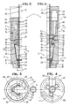
- FIGS. 1 to 5 Reference is made, more particularly, to FIGS. 1 to 5.
- the connector object of the present invention, consists, on the one hand, of a female part 2, associated with any device and into which is introduced the free end 3 of a tube to be connected 4.
- said connector comprises a male part 5 intended to cooperate with said female part 2 to immobilize this free end 3 of said tube to be connected 4 in the latter.
- the diameter 19 of the latter, at the level of the constriction 16, is at least equal to the diameter 12 of the tube to be connected 4 increased by the peripheral bead 20 equipping the latter at its free end 3.
- the purpose of the peripheral bead 20 is to contribute to the tightness of the fitting 1, this tightness being ensured substantially in the bottom 9 of the well 6.
- this peripheral bead 20 comes to cooperate with the wall 21 of a shoulder or of a frustoconical section 22, with a large opening angle, connecting the frustoconical housing 13 to the cylindrical bore 10.
- the means 23 ensuring, more precisely, the tightness of the connector 1, these are determined according to the nature and the pressure of the fluid conveyed.
- such means 23 can consist of a simple seal 24 with the properties chosen by a person skilled in the art according to determined data, this seal 24 being inserted between the wall of the cylindrical bore 10 and the outer periphery 25 of the tube to be connected 4. In addition, it is brought to cooperate, under these conditions, with the front face 26 of the peripheral bead 20.
- a groove is made, as the case may be, in the external periphery 25 of the tube to be connected 4, or in the wall of the cylindrical bore 10 to accommodate said seal 24.
- these snap-on locking means 29 or retractable steps 30 consist of at least two beams 32 also distributed around the tube to be connected 4 and cooperating, at their upper 33 and lower 34 ends, respectively, with the 'shoulder 17 of the well 6 and the rear face 31 of the peripheral bead 20.
- the housing 13 is preferably of frustoconical shape. Such a configuration decreases, substantially, the risks of buckling of the beams 32 when the compression forces applied to them are high. However, for fittings 1, intended to work in a lower pressure range, this housing 13 can be made in a strictly cylindrical shape.
- the beams 32 are connected, at their upper end 33 and / or their lower end 34, by connecting means 35, of elastic nature, to allow not only the engagement, but also the withdrawal of said beams 32 of the well 6.
- the elastic nature of these connecting means 35 is necessary to give these beams 32 a certain radial mobility, on the one hand, to allow their passage at the constriction 16 disposed at the entrance to the well 6 and, on the other hand, to ensure the cooperation of their upper end 33 with the shoulder 17.
- annular blade 36 split or not will depend, initially, on the method of obtaining the latter, but, moreover, on the type of assembly envisaged of the male part 5 on the tube to be connected 4. In particular, in the event that the peripheral bead 20 equipping the free end 3 of the latter is carried out before this assembly, the operator must be able to fit, laterally, said male part 5 onto said tube to be connected 4. Also, the annular blade 36 must be split, but also have an opening 38 substantially equal to or barely less than the diameter 12 of the tube to be connected 4.
- these snap-on blocking means 29 comprise gripping means 44 considerably facilitating their engagement or withdrawal from the well 6.
- these gripping means 44 are constituted by tongues 45 equipping the upper end 33 of the beams 32 and corresponding to the extension of the core 41 of the latter. More specifically, these tongues 45 are initially folded over the upper edge of said beams 32 so as to span the shoulder 17 formed by the constriction 16 before emerging from the well 6 through the opening 15 of the latter.
- the width of these tongues 45 will be determined so that, after folding above the upper edge of the beams 32, they come to cover, simultaneously, the cutting edges which constitute the upper edges of the parallel wings 39, 40, so as to prevent them from becoming encrusted in the shoulder 17 of the well 6 under the effect of the pressure. Indeed, such result would prevent the subsequent disassembly or reassembly of the connector 1.
- the core 41 of the beams 32 can be extended at the lower end 34 of the latter and then folded over the lower edge of the parallel wings 39, 40 so as to constitute a greater range coming to cooperate with the peripheral bead 20.
- this connector 1 also comprises locking means 46 for the male part 5 in the female part 2. It is indeed necessary to ensure that no radial action can be exerted, in use, on the beams and, finally, unexpectedly causing the free end 3 of the tube to be connected 4 to be released from the female part.
- these locking means 46 consist, on the one hand, of a retaining ring 49 ensuring their connection with the snap-on locking means 29 and, on the other hand, of a lock 48 acting on the latter of so as to immobilize them in the well 6 formed by the female part 2.
- the retaining ring 49 illustrated in FIGS. 1 to 4 and corresponding to a first embodiment, is capable of cooperating with the gripping means 44 of the snap-on locking means 29.
- this retaining ring 49 comprises a central bore 50, of axis coinciding with the axis of the tube to be connected 4 and, in which a recess 51 is machined opening out from said retaining ring 49, in the direction of the well 6, through a constriction 52. In this recess 51 are engaged the free ends 53 of the tongues 45 forming the gripping means 44.
- these tongues 45 are folded so as to move away, radially, from the tube axis to be connected 4 and to be inscribed in a circle of diameter greater than the constriction 52. These tongues 45 are thus immobilized in the retaining ring 49.
- these folded free ends 53 of the tongues 45 can be inserted into cavities 55 arranged in the internal wall of the recess 51.
- cavities 55 avoid the design of a circumferential constriction in the retaining ring 49, a particularly delicate design, in particular when the latter is made of a moldable synthetic material. Indeed, such a circumferential constriction constitutes a negative draft to be avoided in the context of such a process.
- the cavities 55 can be obtained, easily, by means of the use of suitable cores implanted in the mold and which are at the origin of the chimneys 56 present in said retaining ring 49.
- this retaining ring 49 necessarily includes a lateral opening 58 adjusted to the diameter 12 of the tube to be connected 4 to authorize the engagement of said ring. retaining 49 on the latter after forming the peripheral bead 20.
- the internal sleeve 61 is made integral with an annular flange 64 disposed at the end 65, located on the side opposite to the female part 2, of the sleeve 59. Furthermore, it is projecting relative to the end opposite 66 of the latter so that it is able to engage in the well 6 by interposing between the beams 32 and the external wall of the tube to be connected 4.
- this latch 48 must be maintained, partially engaged on the retaining ring 49 so as not to hinder the radial movement of the beams 32.
- this anomaly can be easily detected by means of appropriate sensors during the mounting of these fittings 1 using robotic machines.
- this lock 48 serves to immobilize the snap-on locking means 29 in the well 6 and, on the other hand part, to prevent the lateral disengagement of the male part 5, composed of said snap-on locking means 39 and locking means 46, of the tube to be connected 4.
- this lock 48 or sleeve 59 has a lateral opening with dimensions determined as a function of the section of the tube to be connected 4, this lateral opening 67 being positioned at the right of the lateral opening 58, corresponding to the retaining ring 49, during assembly of the connector 1 on said tube to be connected 4.
- the sleeve 59 also comprises means 68 for pivoting on the retaining ring 49 in order to offset their respective opening 58, 67.
- these means of rotation 68 consist, on the one hand, of semi-circular grooves 69 arranged on the external periphery of the retaining ring 49 and, on the other hand, of bosses 70 present on the internal wall of the sleeve 59 and capable of sliding in said grooves semicircular 69.
- the latter lead, at their ends, to cavities 71, 72 into which the bosses 70 are inserted at the end of rotation of the sleeve 59 on the retaining ring 49.
- the locked position can be identified by means of a cavity 74 leading to the lower end of the grooves 73 and intended to accommodate the bosses 70.
- an opening 75 can be arranged in the wall of the sleeve 59, opening 75 serving to receive, in the locked position, a locking lug 76 integral with the external wall of the retaining ring 49. More specifically, this blocking member 76 will preferably be disposed in line with a chimney 56 present in the retaining ring 49 so that it can be erased, by elasticity effect, at the passage of the sleeve 59.
- the lateral openings 58 and 67 made, respectively, in the retaining ring 49 and in the sleeve 59 are only necessary in the case where the connector 1 is associated with the tube to be connected 4, only after forming the cylindrical bead 20.
- the rotation means 68 are completely unnecessary, only the axial movement of the latch 48 on the retaining ring 49 must be made possible.
- FIGS. 6 and 7 show another embodiment of the locking means 46 corresponding to the case where the connector 1 is permanently associated with the tube to be connected 4.
- These locking means 46 take, however, a configuration substantially identical to those described above. above in the sense that they are composed of a retaining ring 149, intended to cooperate with the gripping means 44 of the snap-on locking means 29, and of a latch 148.
- the retaining ring 149 has a central bore 150 having a recess 151 opening on the side of the male part 5 through constrictions 152. These have the effect of keeping the free ends 53 of the tongues 45, corresponding to the gripping means 44 , in said recess 151. Note that these free ends 53 of the tongues 45 can assume a configuration identical to that described above. Furthermore, just as before, the constrictions 152 may be due to the presence of the cavities 155 arranged in the recess 151.
- these cavities 155 will be obtained by placing, radially, a certain number of cores in the mold, these cores being at the origin of the openings 156 present on the outer periphery of the retaining ring 149.
- the latch 148 is in the form of a socket 161 with external dimensions 162 adjusted to the bore 150 of the retaining ring 149 in order to authorize its engagement in the latter.
- This socket 161 also has an internal diameter 163 which depends on the section of the tube to be connected 4. Thus, it is able to come to be interposed between the outer periphery of said tube to be connected 4 and the beams 32 of the snap-on locking means 29 preventing these from being extracted from the well 6.
- a flange 164 secured to the upper end 165 of said sleeve 161 limits the engagement of the latter in the female part 2 by coming into abutment with the upper face 166 of the retaining ring 149.
- these locking means 46 executed according to the second embodiment are produced by a molding process and, this, in one piece.
- the latch 148 and, in particular, the sleeve 161 is made integral, at several points, at its lower end 167, with the upper edge 168 of the central bore 150 present in the retaining ring 149.
- connection points connecting to the retaining ring 149, the sleeve 161 are brought to yield under the effect of a push exerted on the latter.
- the sleeve 161 is caused to encounter locking lugs 169 which, by elasticity effect, are caused to fade. They then come to slide in grooves 170 formed on the outer periphery 171 of this sleeve 161 and arranged according to generatrices.
- the locking lugs 169 form notches coming into abutment against the lower flanges 172 of the grooves 170. They thus maintain the lock 148 associated with the retaining ring 149 after first fitting the fitting 1.
- the withdrawal of the snap-on locking means 29 from the well 6 can only be obtained after tightening of the beams 32 on the outer periphery of the tube to be connected 4 in order to cross the constriction 16.
- the flexible pipe or the rigid pipe connected by means of a fitting 1 according to the invention can be easily angularly oriented relative to the latter, all the less before the circuit is pressurized hydraulic.
- This characteristic can represent an advantage in particular, in the case where the assembly is carried out under difficult conditions with a minimum of space.
- the connector 1, in accordance with the invention may include angular locating means 175 of the tube to be connected 4 in the well 6.
- locating means 175 consist of fitting on the periphery and at the free end 3 of the tube to be connected 4, beyond the sealing means 23, bosses or edges 176 capable of being inserted in grooves 177 formed in the cylindrical bore 10 located at the bottom 9 of the well 6.
- these locating means 175 make it possible to immobilize in rotation and, this, with a choice of the orientation, of the tubes to be connected 4 relative to the female part of the connector 1 therefore of the apparatus to which it is brought to to be connected.
- the connector 1, in accordance with the invention has serious advantages over the connectors previously used in hydraulic circuits in particular, subjected to high pressures.
- it is able to satisfy all the conditions imposed by the surrounding environment.
- the locking means 46 can be obtained by other methods and, more particularly, in different materials to satisfy, in particular, high operating temperatures, temperatures which the most commonly used thermoplastics cannot withstand.
Landscapes
- Engineering & Computer Science (AREA)
- General Engineering & Computer Science (AREA)
- Mechanical Engineering (AREA)
- Quick-Acting Or Multi-Walled Pipe Joints (AREA)
- Earth Drilling (AREA)
- Non-Disconnectible Joints And Screw-Threaded Joints (AREA)
- Joints With Pressure Members (AREA)
- Non-Reversible Transmitting Devices (AREA)
Priority Applications (1)
| Application Number | Priority Date | Filing Date | Title |
|---|---|---|---|
| AT89440109T ATE77462T1 (de) | 1988-10-14 | 1989-10-09 | Anschlusssystem, insbesondere fuer unter hohem druck stehende hydraulische leitung. |
Applications Claiming Priority (2)
| Application Number | Priority Date | Filing Date | Title |
|---|---|---|---|
| FR8813721A FR2637958B1 (fr) | 1988-10-14 | 1988-10-14 | Raccord, notamment pour circuit hydraulique haute pression |
| FR8813721 | 1988-10-14 |
Publications (2)
| Publication Number | Publication Date |
|---|---|
| EP0364380A1 true EP0364380A1 (de) | 1990-04-18 |
| EP0364380B1 EP0364380B1 (de) | 1992-06-17 |
Family
ID=9371140
Family Applications (1)
| Application Number | Title | Priority Date | Filing Date |
|---|---|---|---|
| EP89440109A Expired - Lifetime EP0364380B1 (de) | 1988-10-14 | 1989-10-09 | Anschlusssystem, insbesondere für unter hohem Druck stehende hydraulische Leitung |
Country Status (7)
| Country | Link |
|---|---|
| US (1) | US5078434A (de) |
| EP (1) | EP0364380B1 (de) |
| JP (1) | JPH02209692A (de) |
| AT (1) | ATE77462T1 (de) |
| DE (1) | DE68901846T2 (de) |
| ES (1) | ES2034736T3 (de) |
| FR (1) | FR2637958B1 (de) |
Cited By (2)
| Publication number | Priority date | Publication date | Assignee | Title |
|---|---|---|---|---|
| EP0456375A1 (de) * | 1990-05-10 | 1991-11-13 | Bundy Corporation | Fluidverbinder |
| FR2715454A1 (fr) * | 1994-01-26 | 1995-07-28 | Caillau Ets | Connexion rapide. |
Families Citing this family (4)
| Publication number | Priority date | Publication date | Assignee | Title |
|---|---|---|---|---|
| US5443289A (en) * | 1992-11-11 | 1995-08-22 | Guest; John D. | Tube couplings |
| AU695807B2 (en) * | 1993-11-16 | 1998-08-20 | Proprietary Technology, Inc. | Quick connector |
| DE102013219285A1 (de) * | 2013-09-25 | 2015-03-26 | Schaeffler Technologies Gmbh & Co. Kg | Vorrichtung wenigstens mit zwei gegeneinander beweglichen Elementen und mit einer Hülse |
| KR102363378B1 (ko) * | 2017-06-12 | 2022-02-15 | 현대자동차주식회사 | 차량용 유압튜브커넥터 |
Citations (4)
| Publication number | Priority date | Publication date | Assignee | Title |
|---|---|---|---|---|
| US3826523A (en) * | 1972-11-22 | 1974-07-30 | Parker Hannifin Corp | Quick connect tube coupling joint |
| FR2291438A1 (fr) * | 1974-11-13 | 1976-06-11 | Gen Motors Corp | Raccord pour conduites |
| US4036515A (en) * | 1976-01-14 | 1977-07-19 | The Hansen Manufacturing Co. | Coupling assembly |
| US4135745A (en) * | 1977-12-23 | 1979-01-23 | Ford Motor Company | Quick connect fluid fitting |
Family Cites Families (8)
| Publication number | Priority date | Publication date | Assignee | Title |
|---|---|---|---|---|
| US2468847A (en) * | 1947-06-17 | 1949-05-03 | Disto Corp | Snap action coupling device |
| US2952482A (en) * | 1957-02-04 | 1960-09-13 | E B Wiggins Oil Tool Company I | Coupling with automatically actuated cam sleeve |
| US2939729A (en) * | 1958-04-09 | 1960-06-07 | Preferred Engineering And Res | Quick disconnect coupling |
| FR2012796A1 (de) * | 1969-05-23 | 1970-03-27 | Legris Fils | |
| US3997196A (en) * | 1975-01-20 | 1976-12-14 | The Hansen Manufacturing Co. | Coupling assembly |
| IT8534836V0 (it) * | 1985-04-02 | 1985-04-02 | Gf Srl | Raccordo ad innesto rapido per tubi flessibili in genere |
| US4691943A (en) * | 1985-04-24 | 1987-09-08 | Schmelzer Corporation | Quick connect fluid fitting assembly |
| IT1187599B (it) * | 1985-10-22 | 1987-12-23 | Protec Pordenonese Spa | Giunto a tenuta per tubazioni flessibili di tipo perfezionato |
-
1988
- 1988-10-14 FR FR8813721A patent/FR2637958B1/fr not_active Expired - Lifetime
-
1989
- 1989-10-09 DE DE8989440109T patent/DE68901846T2/de not_active Expired - Fee Related
- 1989-10-09 ES ES198989440109T patent/ES2034736T3/es not_active Expired - Lifetime
- 1989-10-09 AT AT89440109T patent/ATE77462T1/de not_active IP Right Cessation
- 1989-10-09 EP EP89440109A patent/EP0364380B1/de not_active Expired - Lifetime
- 1989-10-16 US US07/429,466 patent/US5078434A/en not_active Expired - Fee Related
- 1989-10-16 JP JP1266357A patent/JPH02209692A/ja active Pending
Patent Citations (4)
| Publication number | Priority date | Publication date | Assignee | Title |
|---|---|---|---|---|
| US3826523A (en) * | 1972-11-22 | 1974-07-30 | Parker Hannifin Corp | Quick connect tube coupling joint |
| FR2291438A1 (fr) * | 1974-11-13 | 1976-06-11 | Gen Motors Corp | Raccord pour conduites |
| US4036515A (en) * | 1976-01-14 | 1977-07-19 | The Hansen Manufacturing Co. | Coupling assembly |
| US4135745A (en) * | 1977-12-23 | 1979-01-23 | Ford Motor Company | Quick connect fluid fitting |
Cited By (5)
| Publication number | Priority date | Publication date | Assignee | Title |
|---|---|---|---|---|
| EP0456375A1 (de) * | 1990-05-10 | 1991-11-13 | Bundy Corporation | Fluidverbinder |
| FR2715454A1 (fr) * | 1994-01-26 | 1995-07-28 | Caillau Ets | Connexion rapide. |
| EP0665401A1 (de) * | 1994-01-26 | 1995-08-02 | ETABLISSEMENTS CAILLAU, Société anonyme à Directoire et Conseil de Surveillance | Schnellverbindung |
| US5496074A (en) * | 1994-01-26 | 1996-03-05 | Etablissements Caillau | Quick connection |
| CN1045654C (zh) * | 1994-01-26 | 1999-10-13 | 卡劳公司 | 快速连接机构 |
Also Published As
| Publication number | Publication date |
|---|---|
| US5078434A (en) | 1992-01-07 |
| FR2637958B1 (fr) | 1990-12-28 |
| ES2034736T3 (es) | 1993-04-01 |
| ATE77462T1 (de) | 1992-07-15 |
| FR2637958A1 (fr) | 1990-04-20 |
| DE68901846D1 (de) | 1992-07-23 |
| JPH02209692A (ja) | 1990-08-21 |
| EP0364380B1 (de) | 1992-06-17 |
| DE68901846T2 (de) | 1993-02-18 |
Similar Documents
| Publication | Publication Date | Title |
|---|---|---|
| EP2878873B1 (de) | Patronenartige schnellkupplungsvorrichtung | |
| EP2908042B1 (de) | Bajonettverbindung zur lösbaren Verbindung von Kanalisationsrohren | |
| FR2942650A1 (fr) | Dispositif de couplage de connexion rapide | |
| FR2786848A1 (fr) | Coupleur a billes | |
| FR2935457A1 (fr) | Connecteur rapide a stabilisation laterale | |
| FR2845149A1 (fr) | Dispositif et structure anti-rotation pour tuyau et raccord | |
| FR2930904A1 (fr) | Assemblage de raccord rapide et outil de degagement | |
| EP3501737B1 (de) | Werkzeug und verfahren zum einbauen einer dichtungsfuge durch ermöglichen einer vorpressung zum zusammenbau von zwei rohrförmigen teilen | |
| EP3220034A1 (de) | Kupplungselement für die verbindung von flüssigkeitsführenden bauteilen und kupplung mit einem solchen element. | |
| EP3356718B1 (de) | Fluidkreislauf sowie dessen herstellungsverfahren | |
| EP0989348B1 (de) | Vorrichtung zum Schnellverbinden von Rohren | |
| EP4124788A1 (de) | Steckanschlusselement eines fluidanschlusses und ein solches steckelement umfassender fluidanschluss | |
| FR2836203A1 (fr) | Raccord destine a relier des conduites hydrauliques | |
| EP0346163A1 (de) | Vorrichtung zur Verbindung von Rohren, insbesondere für Gas | |
| EP0364380B1 (de) | Anschlusssystem, insbesondere für unter hohem Druck stehende hydraulische Leitung | |
| EP2162663A2 (de) | Steckverbinder mit verbesserter aussenreinigung | |
| WO2015136161A1 (fr) | Dispositif de raccordement avec un verrou de connexion tournant | |
| EP2101097A1 (de) | Anschlussvorrichtung für den Transfer eines Fluids, Kreislauf, der diese Vorrichtung umfasst, und entsprechendes Montage-/Demontageverfahren | |
| FR3016950A1 (fr) | Raccord pour circuit de transport de fluide et circuit de transport de fluide comprenant un tel raccord | |
| EP1020677B1 (de) | Verbinderanordnung | |
| EP1571383B1 (de) | Pressfitting mit einem schneidbaren Prüfring | |
| EP3602696B1 (de) | Rundsteckverbinder mit dichtungsdurchgangsöse und haltering | |
| FR3059738B1 (fr) | Agrafe universelle | |
| WO2008009788A1 (fr) | Raccord metallique a position de verrouillage | |
| FR2636715A1 (fr) | Raccord a tuyaux |
Legal Events
| Date | Code | Title | Description |
|---|---|---|---|
| PUAI | Public reference made under article 153(3) epc to a published international application that has entered the european phase |
Free format text: ORIGINAL CODE: 0009012 |
|
| AK | Designated contracting states |
Kind code of ref document: A1 Designated state(s): AT BE CH DE ES GB GR IT LI LU NL SE |
|
| 17P | Request for examination filed |
Effective date: 19900625 |
|
| 17Q | First examination report despatched |
Effective date: 19910524 |
|
| GRAA | (expected) grant |
Free format text: ORIGINAL CODE: 0009210 |
|
| AK | Designated contracting states |
Kind code of ref document: B1 Designated state(s): AT BE CH DE ES GB GR IT LI LU NL SE |
|
| PG25 | Lapsed in a contracting state [announced via postgrant information from national office to epo] |
Ref country code: NL Effective date: 19920617 Ref country code: GR Free format text: LAPSE BECAUSE OF FAILURE TO SUBMIT A TRANSLATION OF THE DESCRIPTION OR TO PAY THE FEE WITHIN THE PRESCRIBED TIME-LIMIT Effective date: 19920617 Ref country code: AT Effective date: 19920617 |
|
| REF | Corresponds to: |
Ref document number: 77462 Country of ref document: AT Date of ref document: 19920715 Kind code of ref document: T |
|
| REF | Corresponds to: |
Ref document number: 68901846 Country of ref document: DE Date of ref document: 19920723 |
|
| ITF | It: translation for a ep patent filed | ||
| GBT | Gb: translation of ep patent filed (gb section 77(6)(a)/1977) | ||
| PG25 | Lapsed in a contracting state [announced via postgrant information from national office to epo] |
Ref country code: LU Free format text: LAPSE BECAUSE OF NON-PAYMENT OF DUE FEES Effective date: 19921031 Ref country code: LI Effective date: 19921031 Ref country code: CH Effective date: 19921031 Ref country code: BE Effective date: 19921031 |
|
| NLV1 | Nl: lapsed or annulled due to failure to fulfill the requirements of art. 29p and 29m of the patents act | ||
| REG | Reference to a national code |
Ref country code: ES Ref legal event code: FG2A Ref document number: 2034736 Country of ref document: ES Kind code of ref document: T3 |
|
| PLBE | No opposition filed within time limit |
Free format text: ORIGINAL CODE: 0009261 |
|
| STAA | Information on the status of an ep patent application or granted ep patent |
Free format text: STATUS: NO OPPOSITION FILED WITHIN TIME LIMIT |
|
| BERE | Be: lapsed |
Owner name: SOC. DES FLEXIBLES ANOFLEX Effective date: 19921031 |
|
| 26N | No opposition filed | ||
| REG | Reference to a national code |
Ref country code: CH Ref legal event code: PL |
|
| EAL | Se: european patent in force in sweden |
Ref document number: 89440109.0 |
|
| PGFP | Annual fee paid to national office [announced via postgrant information from national office to epo] |
Ref country code: GB Payment date: 19960930 Year of fee payment: 8 |
|
| PGFP | Annual fee paid to national office [announced via postgrant information from national office to epo] |
Ref country code: SE Payment date: 19961016 Year of fee payment: 8 |
|
| PGFP | Annual fee paid to national office [announced via postgrant information from national office to epo] |
Ref country code: DE Payment date: 19961018 Year of fee payment: 8 |
|
| PGFP | Annual fee paid to national office [announced via postgrant information from national office to epo] |
Ref country code: ES Payment date: 19961030 Year of fee payment: 8 |
|
| PG25 | Lapsed in a contracting state [announced via postgrant information from national office to epo] |
Ref country code: GB Free format text: LAPSE BECAUSE OF NON-PAYMENT OF DUE FEES Effective date: 19971009 |
|
| PG25 | Lapsed in a contracting state [announced via postgrant information from national office to epo] |
Ref country code: SE Free format text: LAPSE BECAUSE OF NON-PAYMENT OF DUE FEES Effective date: 19971010 Ref country code: ES Free format text: LAPSE BECAUSE OF THE APPLICANT RENOUNCES Effective date: 19971010 |
|
| GBPC | Gb: european patent ceased through non-payment of renewal fee |
Effective date: 19971009 |
|
| PG25 | Lapsed in a contracting state [announced via postgrant information from national office to epo] |
Ref country code: DE Free format text: LAPSE BECAUSE OF NON-PAYMENT OF DUE FEES Effective date: 19980701 |
|
| EUG | Se: european patent has lapsed |
Ref document number: 89440109.0 |
|
| REG | Reference to a national code |
Ref country code: ES Ref legal event code: FD2A Effective date: 20001009 |
|
| PG25 | Lapsed in a contracting state [announced via postgrant information from national office to epo] |
Ref country code: IT Free format text: LAPSE BECAUSE OF NON-PAYMENT OF DUE FEES;WARNING: LAPSES OF ITALIAN PATENTS WITH EFFECTIVE DATE BEFORE 2007 MAY HAVE OCCURRED AT ANY TIME BEFORE 2007. THE CORRECT EFFECTIVE DATE MAY BE DIFFERENT FROM THE ONE RECORDED. Effective date: 20051009 |