EP0364513B1 - Modulierendes ventil zwecks langsamfahrt bei automatischer drucksteuerung in einem getriebesteuersystem - Google Patents
Modulierendes ventil zwecks langsamfahrt bei automatischer drucksteuerung in einem getriebesteuersystem Download PDFInfo
- Publication number
- EP0364513B1 EP0364513B1 EP89901973A EP89901973A EP0364513B1 EP 0364513 B1 EP0364513 B1 EP 0364513B1 EP 89901973 A EP89901973 A EP 89901973A EP 89901973 A EP89901973 A EP 89901973A EP 0364513 B1 EP0364513 B1 EP 0364513B1
- Authority
- EP
- European Patent Office
- Prior art keywords
- pressure
- pressure chamber
- inching
- bore
- fluid
- Prior art date
- Legal status (The legal status is an assumption and is not a legal conclusion. Google has not performed a legal analysis and makes no representation as to the accuracy of the status listed.)
- Expired - Lifetime
Links
- 239000012530 fluid Substances 0.000 claims abstract description 79
- 230000005540 biological transmission Effects 0.000 claims abstract description 16
- 230000007246 mechanism Effects 0.000 claims description 21
- 241000237858 Gastropoda Species 0.000 claims description 6
- 230000000903 blocking effect Effects 0.000 claims description 5
- 230000004044 response Effects 0.000 claims description 4
- 238000006073 displacement reaction Methods 0.000 abstract 1
- 230000008859 change Effects 0.000 description 2
- 230000036461 convulsion Effects 0.000 description 2
- 230000001627 detrimental effect Effects 0.000 description 2
- 230000002093 peripheral effect Effects 0.000 description 2
- 230000002159 abnormal effect Effects 0.000 description 1
- 230000003247 decreasing effect Effects 0.000 description 1
- 230000000994 depressogenic effect Effects 0.000 description 1
- 230000003993 interaction Effects 0.000 description 1
- 230000002028 premature Effects 0.000 description 1
- 230000035939 shock Effects 0.000 description 1
- 238000011144 upstream manufacturing Methods 0.000 description 1
Images


Classifications
-
- F—MECHANICAL ENGINEERING; LIGHTING; HEATING; WEAPONS; BLASTING
- F16—ENGINEERING ELEMENTS AND UNITS; GENERAL MEASURES FOR PRODUCING AND MAINTAINING EFFECTIVE FUNCTIONING OF MACHINES OR INSTALLATIONS; THERMAL INSULATION IN GENERAL
- F16D—COUPLINGS FOR TRANSMITTING ROTATION; CLUTCHES; BRAKES
- F16D48/00—External control of clutches
- F16D48/02—Control by fluid pressure
- F16D48/0206—Control by fluid pressure in a system with a plurality of fluid-actuated clutches
-
- B—PERFORMING OPERATIONS; TRANSPORTING
- B60—VEHICLES IN GENERAL
- B60W—CONJOINT CONTROL OF VEHICLE SUB-UNITS OF DIFFERENT TYPE OR DIFFERENT FUNCTION; CONTROL SYSTEMS SPECIALLY ADAPTED FOR HYBRID VEHICLES; ROAD VEHICLE DRIVE CONTROL SYSTEMS FOR PURPOSES NOT RELATED TO THE CONTROL OF A PARTICULAR SUB-UNIT
- B60W30/00—Purposes of road vehicle drive control systems not related to the control of a particular sub-unit, e.g. of systems using conjoint control of vehicle sub-units
- B60W30/18—Propelling the vehicle
- B60W30/18009—Propelling the vehicle related to particular drive situations
- B60W30/18063—Creeping
-
- F—MECHANICAL ENGINEERING; LIGHTING; HEATING; WEAPONS; BLASTING
- F16—ENGINEERING ELEMENTS AND UNITS; GENERAL MEASURES FOR PRODUCING AND MAINTAINING EFFECTIVE FUNCTIONING OF MACHINES OR INSTALLATIONS; THERMAL INSULATION IN GENERAL
- F16D—COUPLINGS FOR TRANSMITTING ROTATION; CLUTCHES; BRAKES
- F16D25/00—Fluid-actuated clutches
- F16D25/12—Details not specific to one of the before-mentioned types
- F16D25/14—Fluid pressure control
-
- F—MECHANICAL ENGINEERING; LIGHTING; HEATING; WEAPONS; BLASTING
- F16—ENGINEERING ELEMENTS AND UNITS; GENERAL MEASURES FOR PRODUCING AND MAINTAINING EFFECTIVE FUNCTIONING OF MACHINES OR INSTALLATIONS; THERMAL INSULATION IN GENERAL
- F16D—COUPLINGS FOR TRANSMITTING ROTATION; CLUTCHES; BRAKES
- F16D48/00—External control of clutches
- F16D48/02—Control by fluid pressure
-
- F—MECHANICAL ENGINEERING; LIGHTING; HEATING; WEAPONS; BLASTING
- F16—ENGINEERING ELEMENTS AND UNITS; GENERAL MEASURES FOR PRODUCING AND MAINTAINING EFFECTIVE FUNCTIONING OF MACHINES OR INSTALLATIONS; THERMAL INSULATION IN GENERAL
- F16D—COUPLINGS FOR TRANSMITTING ROTATION; CLUTCHES; BRAKES
- F16D48/00—External control of clutches
- F16D48/02—Control by fluid pressure
- F16D2048/0221—Valves for clutch control systems; Details thereof
-
- F—MECHANICAL ENGINEERING; LIGHTING; HEATING; WEAPONS; BLASTING
- F16—ENGINEERING ELEMENTS AND UNITS; GENERAL MEASURES FOR PRODUCING AND MAINTAINING EFFECTIVE FUNCTIONING OF MACHINES OR INSTALLATIONS; THERMAL INSULATION IN GENERAL
- F16D—COUPLINGS FOR TRANSMITTING ROTATION; CLUTCHES; BRAKES
- F16D48/00—External control of clutches
- F16D48/02—Control by fluid pressure
- F16D2048/0257—Hydraulic circuit layouts, i.e. details of hydraulic circuit elements or the arrangement thereof
- F16D2048/0269—Single valve for switching between fluid supply to actuation cylinder or draining to the sump
-
- F—MECHANICAL ENGINEERING; LIGHTING; HEATING; WEAPONS; BLASTING
- F16—ENGINEERING ELEMENTS AND UNITS; GENERAL MEASURES FOR PRODUCING AND MAINTAINING EFFECTIVE FUNCTIONING OF MACHINES OR INSTALLATIONS; THERMAL INSULATION IN GENERAL
- F16D—COUPLINGS FOR TRANSMITTING ROTATION; CLUTCHES; BRAKES
- F16D2500/00—External control of clutches by electric or electronic means
- F16D2500/70—Details about the implementation of the control system
- F16D2500/702—Look-up tables
- F16D2500/70294—Valve look-up tables
Definitions
- This invention relates generally to a modulating inching valve for use in a vehicle transmission control system and more particularly to a modulating inching valve having selective control of the rate of pressure rise to the fluid actuated device during inching over a preselected range of the total inching pedal travel and an automatic control over the rate of pressure rise during the remaining portion of the input control.
- gear sets In transmissions having a plurality of gear sets for establishing different speed ratios and different directional modes, the gear sets must be separately actuated by individual fluid actuated devices, such as disc-type friction clutches.
- individual fluid actuated devices such as disc-type friction clutches.
- one set of the speed or directional clutches is heavier and more durable in order to absorb the shock loads induced when transmitting power to the drive train of the vehicle. During operation, the heavier clutch is engaged last. In many applications, the directional clutch is the heavier clutch.
- U.S.-A-3,923,076 teaches a control system for a transmission having directional and speed clutches and a control valve for controlling the rate of pressure rise to the clutches during engagement thereof.
- This system also teaches an inching control valve which allows, through operator input, the ability to inch a vehicle through a given range of operator input. By controlling a signal to the remote pressure modulating valve, the reengagement of the clutch during the last portion of the inching pedal control is automatically controlled.
- This system requires additional external lines to interconnect the modulating relief valve and the inching control valve to accomplish the desired objective. The use of small signal lines interconnected between two remotely located valves is detrimental since they are subject to breakage and are also sensitive to varying temperatures.
- U.S.-A-4,349,094 teaches a control system for a transmission having friction clutches.
- This system provides an arrangement for modulating the rate of pressure rise to the clutches during engagement thereof.
- This system also includes an operator control lever which can vary the operating pressure level to the clutch allowing the operator to selectively adjust the pressure level to the clutch or allows the operator to selectively vary the pressure level of the fluid to the clutch for inching of the vehicle.
- U.S.-A-4,676,348 teaches a control system for a transmission having directional and speed clutches and a pressure modulating valve for controlling the rate of pressure rise to the respective clutches.
- This arrangement also teaches a mechanism using a plurality of slugs slidably disposed in the modulating valve to provide a lower standby pressure on the clutches following full engagement of the clutches.
- the mechanism which establishes the lower standby pressure to the actuated clutches is responsive to the pressure level in the clutches reaching a predetermined magnitude prior to the lower standby pressure being initiated. This arrangement does not provide any inching control of the vehicle.
- EP-A-0013475 discloses an apparatus for controlling the supply of fluid to a plurality of mechanisms.
- This apparatus comprises a single valve assembly for controlling the supply of pressurised fluid from a fluid source to first, second and third controlled members, in which the single valve assembly has a first relief valve segment to relieve the pressure of fluid flowing from the source to the third controlled member, a second relief valve segment to relieve the pressure of fluid relieved by the first relief valve segment and a third valve segment to direct the fluid relieved by the first relief valve segment to the first and second controlled members.
- a movable lever is connected to the third valve segment to shift this valve segment and control the direction of the fluid.
- This apparatus has an inching capability, however this is provided by the operator moving the lever manually to obtain a desired inching pressure.
- a modulating inching valve for use in a vehicle transmission control system having a source of pressurised fluid, a reservoir, a plurality of fluid actuated devices, a plurality of valve mechanisms operative to selectively control the respective plurality of fluid actuated devices, and a pressure control valve operative to control the pressure level of the fluid to the fluid actuated devices, comprises a housing having a bore defined therein, an inlet port operatively connectable to the source of pressurized fluid, an outlet port operatively connectable to at least one of the fluid actuated devices, and first and second drain ports, each of the ports intersecting the bore at axially spaced locations; valve means for controlling the rate of pressure rise between the inlet port and the outlet port, the valve means being slidably disposed in the bore and having a valving element operative in use to control fluid communication between the inlet port and the outlet port, pressure responsive means for biasing the valving element to a position blocking communication between the inlet port and the outlet port and opening communication between
- a fluid system 10 is shown for use in a vehicle (not shown) to selectively control the engagement and disengagement of a plurality of fluid actuated devices, such as a speed clutch 12 and a directional clutch 14 and to provide inching control of the vehicle.
- a plurality of fluid actuated devices such as a speed clutch 12 and a directional clutch 14
- the fluid system 10 includes a source of pressurized fluid, such as a pump 16, adapted to receive fluid from a reservoir 18 through a conduit 20.
- a plurality of valve mechanisms such as speed selector valve 22 and directional selector valve 24, are included in the fluid system 10 and are connected to the pump 16 by respective distribution conduits 26,28,30.
- a conduit 32 connects the speed clutch 12 to the speed selector valve 22 while a conduit 34 connects the directional clutch 14 with the directional selector valve 24.
- Each of the selector valves 22,24 are respectively connected to the reservoir 18 by conduits 36,38.
- a pressure control valve 40 is connected to the pump 16 by a conduit 42 and the distribution conduit 16 and is operational to control the maximum pressure level of the fluid from the pump 16.
- An orifice 44 is located in the distribution conduit 30 upstream of the directional selector valve 24 and operative to ensure that the speed clutch 12 fills prior to the directional clutch 14.
- a modulating inching valve 50 is located in the distribution conduit 30 and is operative to control the fluid pressure in the distribution conduit 30 downstream thereof.
- the modulating inching valve 50 includes a housing 52 having a bore 54 defined therein, an inlet port 56, an outlet port 58, and first and second drain ports 60,62 each intersecting the bore 54 at axially spaced locations.
- a third drain port 64 also intersects the bore 54 and along with the the first and second drain ports 60,62 are connected to the reservoir 18 through a common passageway 66 and a conduit 68.
- An end chamber 70 is connected to the tank 18 through a fourth drain port 72.
- Valve means 80 for controlling the rate of pressure rise between the inlet port 56 and the outlet port 58 is slidably disposed in the bore 54.
- the valve means 80 has a valving element 82, pressure responsive means 84, means 86 for biasing the valving element 82, and a load piston 88.
- the valving element 82 has first and second ends 90,92, a blind bore 94 located adjacent the first end 90 of the valving element 82, and a radial passageway 96 interconnecting the bottom of the blind bore 94 and a peripheral groove 98 of the valving element 82.
- a slug 100 is slidably disposed in the blind bore 90 and defines a pressure chamber 102 between the bottom of the blind bore 94 and the slug 100.
- the blind bore 94, slug 100, pressure chamber 102, and the radial passageway 96 make up the pressure responsive means 84.
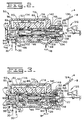
- the means 86 for biasing the valving element 82 includes a spring assembly 106 having inner and outer springs and is disposed in the bore 54 between the second end 92 of the valving element 82 and the load piston 88. As shown in Figs. 2 and 3, the outer spring of the spring assembly 106 has a length sufficient to engage the load piston 88 only during a portion of the load piston's movement.
- the load piston 88 has a bore 108 defined therein and is slidably disposed in the bore 54 adjacent the second end 92 of the valving element 82.
- a pressure chamber 110 is defined in the bore 54 at a location adjacent the load piston 88 and at the end of the bore 54 opposite to the valving element 82.
- Restrictive passage means 112 for controllably interconnecting the inlet port 56 and the pressure chamber 110 is provided in the housing 52 and includes a passage 114 with an orifice 116 defined therein.
- An input actuator mechanism 120 is disposed in the bore 54 adjacent the pressure chamber 110 and is operative in use to move through a predetermined travel distance.
- An input plunger 122 is operatiavely associated with the input actuator mechanism 120 and is connected to an inching pedal 124 through associated linkages 126.
- the inching pedal 124 is movable through a distance A-B to obtain a predetermined travel distance of the input plunger 122 with respect to the input actuator mechanism 120. In order to inch the vehicle, the inching pedal 124 is depressed to the fully actuated position B and gradually released to obtain the desired vehicle inching.
- the input actuator mechanism 120 includes a sleeve 128, an input member 130, and a spring 132 disposed between the sleeve 128 and the input member 130.
- the sleeve 128 has a bore 134 defined therein and the sleeve 128 is movable between first and second positions.
- the input member 130 has a first end portion 136 slidably disposed within the bore 134 of the sleeve 128 and the bore 108 of the load piston 88 and is movable through the predetermined travel distance as established by the input plunger 122.
- the input member 130 has a second end portion 138 and a shoulder 140 is defined on the second end portion 138 adjacent the first end portion 136.
- a stop 142 such as a snap ring, is located on the first end portion 136 of the input member 130 and is operative to limit the amount of travel of the load piston 88 on the first end portion 136.
- a passageway 144 is defined in the first end portion 136 of the input member 130 and has first and second radial openings 146,148 opening to the peripheral surface of the first end portion 136 at axially spaced locations.
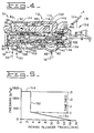
- the graph illustrates the relationship of the inching input plunger travel versus the pressure level in the control system.
- the graph also illustrates the time relationship of the pressure level when the modulating inching valve is in the automatic mode of operation.
- the pressure level in the system acting on the clutch 14 is increasing at a gradual rate as the input member 130 is being released during inching operation.
- the selective control of the operator is ended and the automatic mode of the modulating inching valve 50 is initiated.
- a vertical line 152 on the graph indicates the increase in pressure that occurs once the automatic mode is initiated.
- the increase in pressure is accomplished over a predetermined period of time regardless of the position of the inching input plunger 122 in its last portion of travel distance.
- a horizontal line 154 on the graph indicates the remaining travel distance of the inching input plunger and further indicates that there is no change in the system operating pressure with respect to the remaining portion of the inching input plunger travel since the system pressure is being independently controlled by the pressure control valve 40.
- FIG. 6 another embodiment of the fluid system 10 is disclosed which includes a modified form of the modulating inching valve 50.
- the fluid system 10 of the subject embodiment includes an additional fluid actuated device, such as a clutch 160, and a selector valve 24′ capable of controlling fluid flow to either the fluid actuator device 14 or the fluid actuator device 160.
- the valve means 80 of the subject embodiment includes a valving element 82′ having first and second ends 90, 92 and defines a stepped blind bore 162 adjacent the first end 90.
- the slug 100 is slidably disposed in the stepped blind bore 162 to define the pressure chamber 102 as previously set forth in the first embodiment.
- the first radial passageway 96 as previously described, interconnects the pressure chamber 102 with the outlet port 58.
- a second slug 164 having a cross-sectional area greater than the first slug 100 is slidably disposed in the stepped blind bore 162 adjacent the first slug 100 to define a second pressure chamber 166 between the first and second slugs 100,164.
- a second radial passageway 168 is defined in the valving element 82′ and communicates the second pressure chamber 166 with distribution passage 30 downstream of the modulating inching valve 50 through a conduit 170.
- a two position valve 172 is disposed in the conduit 170 and is movable in response to a control signal S from a first position at which communication of pressurized fluid therethrough is blocked and the pressure chamber 166 is in open communication with the reservoir 18 and a second position at which pressurized fluid is in open communication with the pressure chamber 166.
- the control signal S being generated in response to predetermined vehicle gear ratios.
- a third slug 174 having a cross-sectional area greater than that of the second slug 164 is slidably disposed in the stepped blind bore 162 adjacent the second slug 164 and defines a third pressure chamber 176.
- a third radial passageway 178 communicates, through a conduit 180, the third pressure chamber 176 with the additional clutch 160 downstream of the selector valve 24′.
- the stepped bore 162 of the valving element 82′ along with the first, second and third pressure chambers 102,166,176 and the first, second and third radial passageways 96,168,178 make up a means 184 for establishing a plurality of different biasing forces.
- the means 184 for establishing the plurality of biasing forces is responsive when in use to various operating conditions of the vehicle and is part of the pressure responsive means 84.
- the pressure control valve 40 could be a modulating pressure relief valve as is commonly used in many transmission control systems to control the rate of pressure to the clutches.
- the selector valves 22,24,24′ could also be operated electrically or hydraulically without departing from the essence of the invention.
- the fluid system 10 is in an operational mode in which the clutches 12 and 14 are engaged by pressurized fluid from the pump 16 being directed through the respective speed and direction selector valves 22,24.
- the pressure control valve 40 maintains a maximum predetermined pressure in the distribution conduits 26,28,30.
- the orifice 44 restricts fluid flow through the distribution conduit 30 in order to ensure that the speed clutch 12 is filled prior to filling of the directional clutch 14.
- the inching pedal 124 is in its unactuated position A and there is free communication of the fluid in the distribution conduit 30 between the inlet port 56 and the outlet port 58 of the modulating inching valve 50.
- pressurized fluid in the outlet port 58 is directed to the pressure chamber 102 through the radial passage 96.
- the pressurized fluid creates an effective force urging the valving element 82 towards a position in which communication between the inlet port 56 and the outlet port 58 is blocked.
- pressurized fluid from the inlet port 56 is directed through the passage 114 across the orifice 116 into the pressure chamber 110. This pressurized fluid in pressure chamber 110 urges the load piston 88 towards the valving element 82.
- the pressure level in pressure chamber 110 cannot be maintained and is quickly reduced to a substantially zero pressure level. Due to the loss of fluid pressure within the pressure chamber 110 and the biasing force of the spring assembly 106, the load piston 88 moves away from the valving element 82. The load piston 88 moves until it abuts the stop 142 and is maintained in that position. At this position of the load piston 88, the biasing force of the spring assembly 106 is substantially zero. Consequently, the effective force in pressure chamber 102 is sufficient to move the valving element 82 to the position at which the inlet port 56 is blocked from the outlet port 58.
- the outlet port 58 is being simultaneously opened to the first drain port 60. Since the effective force holding the valving element 82 in the position to close the inlet port 56 is the result of the pressurized fluid in the outlet port 58, the valving element 82 maintains a position in which the outlet port 58 is in communication with the first drain port 60 and communication of the inlet port 56 is blocked from the outlet port 58.
- the valving element 82 will maintain a position in which a limited amount of fluid from the inlet port 56 is allowed to pass to the outlet port 58 and through the radial passageway 96 to the pressure chamber 102 to establish an effective force to resist any limited biasing force from spring assembly 106.
- the operator moves the inching pedal 124 from the position B towards the position A.
- the input member 130 is moved to an intermediate position.
- the passageway 144 is still communicating the pressure chamber 110 with the second drain port 62.
- the stop 142 urges the load piston 88 towards the valving element 82.
- the valving element 82 opens communication between the inlet port 56 and the outlet port 58, the communication between the outlet port 58 and first drain port 60 is blocked.
- the pressure level in the outlet port 58 increases, the pressure level in the pressure chamber 102 simultaneously increases and the resulting effective force resists the bias of the inner spring of the spring assembly 106 and maintains the valving element 82 in a position to sustain a pressure level in the outlet port 58 that is proportional to the position of the input member 130.
- the first radial opening 146 of the passageway 144 is being partially closed off by the relationship of the first end portion 136 of the input member 130 sliding within the bore 134 of the sleeve 128.
- the pressure level of the fluid in the pressure chamber 110 cannot increase. Also, during this phase in the operation, the stop 142 is causing the load piston to move at the same rate that the input member 130 is being moved. Consequently, as long as the radial opening 146 of the passageway 144 is in open communication with the second drain port 62, the operator has full control over inching of the vehicle.
- the inching pedal 124 has been further moved by the operator from the position B towards the position A.
- the sleeve 128 has moved from its initial position to its second position against the bias of the spring 132. This happened as a result of the operator moving the inching pedal 124 from the position disclosed in Fig. 3 to the position shown in Fig. 4.
- This extra amount of movement resulted in the radial opening 146 of the passageway 144 being further restricted to the point that the fluid in the pressure chamber 110 is pressurized.
- the load piston is now in contact with the outer spring of the spring assembly 106.
- the additional biasing force causes a greater rate of increase in the system control pressure. It should be recognized that the length of the outer spring could be increased or decreased in order to obtain the additional spring force when desired. Since the fluid flow into the pressure chamber 110 is entering at a controlled rate, the movement of the load piston towards the valving element is likewise moving at a controlled rate which increases the force on the spring assembly at a controlled rate.
- the pressure level in the outlet port 58 is increased due to the opening of the inlet port 56 to the outlet port 58 being increased.
- the increase in fluid pressure at the outlet port 58 is also communicated with the pressure chamber 102 through the radial passageway 96 to provide an effective force resisting the valving element 82 from moving to a position to further open communication of the inlet port 56 with the outlet port 58.
- the pressure level in the outlet port 58 is effectively controlled at a predetermined level.
- the modulating inching valve 50 is in an automatic mode of operation. During this phase of operation, the operator has no control over the rate of pressure rise in the outlet port 58.
- the line 150 would be representative of the operation of the system in the mode of operation in which the operator has full control over inching of the vehicle by controlling the pressure rise rate in outlet port 58.
- the inching pedal travel is at its position B, which in the graph is representative of 16 mm (.63 inches)
- the pressure in the outlet port 58 would be zero.
- the inching pedal 124 is gradually released, the pressure at the outlet port 58 would increase from the zero level to an increased level.
- the pressure level at outlet port 58 would be approximately 250 kpa (36 psi).
- This particular pressure level at outlet 58 acting on the fluid actuator device 14 provides a particular rate of inching of the vehicle. If the operator wants to have slower inching, he would further depress the inching pedal 124 and conversely, if he wants increased inching, he would further release the inching pedal 124. Movements of the inching pedal 124 between 3 mm (.12 inches) and 16 mm will give varying rates of inching movement of the vehicle due to a changing pressure level acting on the clutch 14.
- the sleeve 128 is quickly biased towards its second position totally blocking the radial opening 146 of the passageway 144 and at this point the operator is no longer in control of the rate of pressure rise in the outlet port 58.
- the modulating inching valve 50 automatically controls the rate of pressure rise and as shown by the vertical line 152, the rate of pressure rise increases from approximately 300 kpa (43.5 psi) to a maximum pressure level of approximately 1,400 kpa (203 psi) in approximately 3/10 of one second. Any movement of the inching pedal 124 between zero travel and 3 mm will have no affect on the rate of pressure rise at the outlet port 58. Consequently, a sudden release of the inching pedal will not subject the system to a harsh, abrupt start.
- the modulating inching valve 50 of the alternate embodiment functions quite similar to that discussed above. Except the modulating inching valve 50 of Fig. 6 can provide modulated inching control at different system pressure level ranges depending on various operating conditions of the vehicle. More specifically, pressurized fluid in the outlet port 58 is simultaneously communicated with the pressure chamber 102 through the radial passageway 96 and functions identically to that set forth in the description of Figs. 1-4.
- a lower system control pressure range for inching of the vehicle in a higher gear ratio is automatically obtained when the operator selects the higher gear ratio.
- the control signal S is generated in response to the selection of the higher gear ratio and is effective to move the two position valve 172 from its first blocking position to its second open position. It is recognized that the control signal S may be hydraulical, electrical, or even manual without departing from the essence of the invention.
- pressurized fluid from the distribution conduit 30 is communicated through conduit 170 and radial passageway 168 to the pressure chamber 166.
- the effective force moving the valving element 82′ towards the position to interrupt flow between inlet port 56 and outlet port 58 is greater.
- the effective pressure level at the outlet port 58 is less than that developed when the valving element 82′ is being biased by the force from the pressure chamber 102.
- a larger force biasing the valving element 82′ towards a position closing communication between inlet port 56 and outlet port 58 results in a lower pressure level in the outlet port 58. This is apparent since the force developed by the spring assembly 106 is constant for a given position.
- the valving element 82′ further restricts the communication between the inlet port 56 and the outlet port 58 resulting in a lower pressure level at the outlet port 58.
- the additional pressure range may be obtained by directing the fluid pressure from the additional clutch 160 when in use to the pressure chamber 176 through the conduit 180 and radial passageway 178. Since the cross-sectional area of the slug 174 is larger than the cross-sectional area of either of the slugs 100,164, an effective force is established which is larger than the effective force of either of the other pressure chambers 102,166. This effective force urges the valving element 82′ toward the position to block fluid communication between the inlet port 56 and the outlet port 58. Again, as stated above, for a given position of the load piston 88, the pressure level of the fluid at the outlet port 58 would be lower than that established by the force from pressure chambers 102,166.
- the effective operating pressure at the outlet port 58 can be automatically controlled at various levels in order to provide inching control at various operating conditions of the vehicle without subjecting the clutches to undue thrust loads which generates excessive heat and attributes to more wear.
- the source of pressurized fluid for the pressure chambers 102,166,176 could be received from other sources. However, it is most expedient to utilize the pressure source that is being directed to the clutch or clutches that are being slipped and to change the cross-sectional area of the slugs utilized in the pressure responsive means 84.
- the modulating inching valve 50 of the fluid system 10 incorporates a valve means 80 to control the rate of pressure rise between the inlet port and the outlet port thereof and an input actuator mechanism 120 to selectively provide a range of system control pressure to the clutch 14.
- the range of system control pressure to the clutch 14 is controlled by the operator through a given portion of his full inching pedal travel and is automatically controlled in the final portion of the inching pedal travel. This relationship allows precise operator inching control when subjecting the clutch 14 to the lower pressure levels.
- the modulating inching valve 50 automatically takes control of the rate of pressure rise and totally re-engages the clutch 14 fully over a predetermined period of time. This happens without the operator being able to override the automatic control.
Landscapes
- Engineering & Computer Science (AREA)
- General Engineering & Computer Science (AREA)
- Mechanical Engineering (AREA)
- Physics & Mathematics (AREA)
- Fluid Mechanics (AREA)
- Automation & Control Theory (AREA)
- Transportation (AREA)
- Hydraulic Clutches, Magnetic Clutches, Fluid Clutches, And Fluid Joints (AREA)
- Control Of Fluid Gearings (AREA)
Claims (11)
Applications Claiming Priority (2)
| Application Number | Priority Date | Filing Date | Title |
|---|---|---|---|
| US160958 | 1988-02-26 | ||
| US07/160,958 US4865176A (en) | 1988-02-26 | 1988-02-26 | Modulating inching valve with automatic pressure control |
Publications (2)
| Publication Number | Publication Date |
|---|---|
| EP0364513A1 EP0364513A1 (de) | 1990-04-25 |
| EP0364513B1 true EP0364513B1 (de) | 1992-07-29 |
Family
ID=22579200
Family Applications (1)
| Application Number | Title | Priority Date | Filing Date |
|---|---|---|---|
| EP89901973A Expired - Lifetime EP0364513B1 (de) | 1988-02-26 | 1988-11-16 | Modulierendes ventil zwecks langsamfahrt bei automatischer drucksteuerung in einem getriebesteuersystem |
Country Status (7)
| Country | Link |
|---|---|
| US (1) | US4865176A (de) |
| EP (1) | EP0364513B1 (de) |
| JP (1) | JPH02503345A (de) |
| KR (1) | KR960016792B1 (de) |
| CA (1) | CA1295915C (de) |
| DE (1) | DE3873339D1 (de) |
| WO (1) | WO1989008208A1 (de) |
Families Citing this family (9)
| Publication number | Priority date | Publication date | Assignee | Title |
|---|---|---|---|---|
| US5101943A (en) * | 1990-11-30 | 1992-04-07 | Ford New Holland, Inc. | Method of controlling inching clutches |
| DE4100672C1 (de) * | 1991-01-11 | 1992-02-20 | Mannesmann Rexroth Gmbh, 8770 Lohr, De | |
| DE19815889A1 (de) * | 1998-04-08 | 1999-10-14 | Mannesmann Rexroth Ag | Inchbremseinrichtung |
| US6647332B1 (en) * | 1998-12-21 | 2003-11-11 | Caterpillar Inc | Electronic inching control strategy |
| US6640950B2 (en) | 2001-12-28 | 2003-11-04 | Caterpillar Inc. | Fluid clutch fill detection system and method |
| DE10302054B4 (de) * | 2003-01-21 | 2018-10-25 | Robert Bosch Gmbh | Verfahren zum Betreiben einer Brennkraftmaschine |
| US7361121B2 (en) * | 2004-08-30 | 2008-04-22 | Komatsu Ltd. | Control device and method for input clutch of work vehicle |
| DE102008045264A1 (de) * | 2008-09-01 | 2010-03-04 | Magna Powertrain Ag & Co Kg | Antriebssystem für ein Kraftfahrzeug |
| US12577991B2 (en) | 2024-06-17 | 2026-03-17 | Caterpillar Inc. | Pressure modulating clutch control assembly |
Family Cites Families (12)
| Publication number | Priority date | Publication date | Assignee | Title |
|---|---|---|---|---|
| US3137311A (en) * | 1962-07-02 | 1964-06-16 | Caterpillar Tractor Co | Manually operated modulation valve |
| US3923076A (en) * | 1973-04-27 | 1975-12-02 | Caterpillar Tractor Co | Transmission control system with dual purpose modulating valve |
| JPS5824805B2 (ja) * | 1974-10-11 | 1983-05-24 | 株式会社小松製作所 | セイギヨベン |
| US4036342A (en) * | 1976-06-28 | 1977-07-19 | Towmotor Corporation | Inching valve with means preventing high pressure inching |
| US4150737A (en) * | 1977-08-03 | 1979-04-24 | Clark Equipment Company | Inching valve |
| IT1084155B (it) * | 1977-08-16 | 1985-05-25 | Trensfluid S R L | Dispositivo idraulico per l'azionamento modulato degli innesti a frizione |
| US4301713A (en) * | 1978-12-07 | 1981-11-24 | Caterpillar Tractor Co. | Apparatus for supplying fluid to a plurality of mechanisms |
| US4474082A (en) * | 1981-09-11 | 1984-10-02 | Borg-Warner Corporation | Control system for power shifted transmission |
| JPS5847629A (ja) * | 1981-09-17 | 1983-03-19 | Kamizaki Kokyu Koki Seisakusho Kk | 移動作業車の変速装置 |
| JPS5981231A (ja) * | 1982-10-29 | 1984-05-10 | Aisin Seiki Co Ltd | インチング制御装置 |
| US4643285A (en) * | 1985-01-14 | 1987-02-17 | J.I. Case Company | Hydraulic control for a master clutch of a transmission |
| US4676348A (en) * | 1986-03-06 | 1987-06-30 | Caterpillar Inc. | Fluid pressure control system having a timed pressure cutback device |
-
1988
- 1988-02-26 US US07/160,958 patent/US4865176A/en not_active Expired - Lifetime
- 1988-11-16 DE DE8989901973T patent/DE3873339D1/de not_active Expired - Lifetime
- 1988-11-16 WO PCT/US1988/004089 patent/WO1989008208A1/en not_active Ceased
- 1988-11-16 KR KR1019890701964A patent/KR960016792B1/ko not_active Expired - Lifetime
- 1988-11-16 JP JP89501936A patent/JPH02503345A/ja active Pending
- 1988-11-16 EP EP89901973A patent/EP0364513B1/de not_active Expired - Lifetime
-
1989
- 1989-02-24 CA CA000592048A patent/CA1295915C/en not_active Expired - Fee Related
Also Published As
| Publication number | Publication date |
|---|---|
| DE3873339D1 (de) | 1992-09-03 |
| WO1989008208A1 (en) | 1989-09-08 |
| CA1295915C (en) | 1992-02-18 |
| EP0364513A1 (de) | 1990-04-25 |
| KR960016792B1 (ko) | 1996-12-21 |
| JPH02503345A (ja) | 1990-10-11 |
| US4865176A (en) | 1989-09-12 |
| KR900700781A (ko) | 1990-08-17 |
Similar Documents
| Publication | Publication Date | Title |
|---|---|---|
| EP0061732B1 (de) | Hydraulisches Steuerungssystem für stufenlos regelbare Riemengetriebe mit hydrodynamischem Drehmomentwandler | |
| EP0980997B1 (de) | Druckregelventil | |
| AU560917B2 (en) | Friction couple cooling system responsive to actuation thereof | |
| EP0015919B1 (de) | Auswahlventil mit druckmodulation | |
| US4751866A (en) | Ratio valve to control unloading of modulating relief valve | |
| US4510822A (en) | Continuously variable V-belt transmission including hydrodynamic transmission unit with lock-up means | |
| US4865176A (en) | Modulating inching valve with automatic pressure control | |
| CA1261231B (en) | Hydraulic circuit for activating a clutch and a throttle valve used in the circuit | |
| US5829560A (en) | Valve assembly in a hydraulic control for a ratio controller in a power transmission | |
| US4422536A (en) | Transmission control system with improved modulation rate regulating valve | |
| US3444968A (en) | Fluid controls for automatically neutralizing a vehicle transmission | |
| US4394827A (en) | Transmission control system with modified friction engaging mechanism actuating pressure | |
| US4646895A (en) | Hydraulic control for a transmission with high-low powershift and masterclutch | |
| US4583624A (en) | Fluid system with selective differential pressure control | |
| US6179107B1 (en) | Trim valve for a fluid operated friction torque transmitting device | |
| US4111071A (en) | Modulating relief valve with hydraulic safety | |
| US4619350A (en) | Clutch operation control system for fluid torque converter of vehicular transmission | |
| US4074796A (en) | Adjustable sequence valve for towing winch hydraulic controls | |
| US4278155A (en) | Draw works transmission control | |
| US6783479B2 (en) | Automatic transmission | |
| US4301713A (en) | Apparatus for supplying fluid to a plurality of mechanisms | |
| US4487304A (en) | Control system for a fluid pressure engaged clutch | |
| EP0414826B1 (de) | Steuervorrichtung zur rückstellung eines lastkolbens | |
| US3487851A (en) | Transmission hydraulic control | |
| EP0019352A2 (de) | Steuervorrichtung für ein Windensystem |
Legal Events
| Date | Code | Title | Description |
|---|---|---|---|
| PUAI | Public reference made under article 153(3) epc to a published international application that has entered the european phase |
Free format text: ORIGINAL CODE: 0009012 |
|
| 17P | Request for examination filed |
Effective date: 19891120 |
|
| AK | Designated contracting states |
Kind code of ref document: A1 Designated state(s): BE DE FR GB IT |
|
| 17Q | First examination report despatched |
Effective date: 19910423 |
|
| GRAA | (expected) grant |
Free format text: ORIGINAL CODE: 0009210 |
|
| AK | Designated contracting states |
Kind code of ref document: B1 Designated state(s): BE DE FR GB IT |
|
| PG25 | Lapsed in a contracting state [announced via postgrant information from national office to epo] |
Ref country code: DE Effective date: 19920729 |
|
| REF | Corresponds to: |
Ref document number: 3873339 Country of ref document: DE Date of ref document: 19920903 |
|
| ET | Fr: translation filed | ||
| ITF | It: translation for a ep patent filed | ||
| PG25 | Lapsed in a contracting state [announced via postgrant information from national office to epo] |
Ref country code: GB Effective date: 19921116 |
|
| PG25 | Lapsed in a contracting state [announced via postgrant information from national office to epo] |
Ref country code: BE Effective date: 19921130 |
|
| BERE | Be: lapsed |
Owner name: CATERPILLAR INC. Effective date: 19921130 |
|
| PLBE | No opposition filed within time limit |
Free format text: ORIGINAL CODE: 0009261 |
|
| STAA | Information on the status of an ep patent application or granted ep patent |
Free format text: STATUS: NO OPPOSITION FILED WITHIN TIME LIMIT |
|
| GBPC | Gb: european patent ceased through non-payment of renewal fee |
Effective date: 19921116 |
|
| 26N | No opposition filed | ||
| PG25 | Lapsed in a contracting state [announced via postgrant information from national office to epo] |
Ref country code: FR Effective date: 19930730 |
|
| REG | Reference to a national code |
Ref country code: FR Ref legal event code: ST |
|
| PG25 | Lapsed in a contracting state [announced via postgrant information from national office to epo] |
Ref country code: IT Free format text: LAPSE BECAUSE OF NON-PAYMENT OF DUE FEES;WARNING: LAPSES OF ITALIAN PATENTS WITH EFFECTIVE DATE BEFORE 2007 MAY HAVE OCCURRED AT ANY TIME BEFORE 2007. THE CORRECT EFFECTIVE DATE MAY BE DIFFERENT FROM THE ONE RECORDED. Effective date: 20051116 |