EP0364527B1 - Recipient a deux cavites - Google Patents
Recipient a deux cavites Download PDFInfo
- Publication number
- EP0364527B1 EP0364527B1 EP89903136A EP89903136A EP0364527B1 EP 0364527 B1 EP0364527 B1 EP 0364527B1 EP 89903136 A EP89903136 A EP 89903136A EP 89903136 A EP89903136 A EP 89903136A EP 0364527 B1 EP0364527 B1 EP 0364527B1
- Authority
- EP
- European Patent Office
- Prior art keywords
- container
- applicator nozzle
- chamber
- container according
- turning cap
- Prior art date
- Legal status (The legal status is an assumption and is not a legal conclusion. Google has not performed a legal analysis and makes no representation as to the accuracy of the status listed.)
- Expired - Lifetime
Links
Images

Classifications
-
- B—PERFORMING OPERATIONS; TRANSPORTING
- B65—CONVEYING; PACKING; STORING; HANDLING THIN OR FILAMENTARY MATERIAL
- B65D—CONTAINERS FOR STORAGE OR TRANSPORT OF ARTICLES OR MATERIALS, e.g. BAGS, BARRELS, BOTTLES, BOXES, CANS, CARTONS, CRATES, DRUMS, JARS, TANKS, HOPPERS, FORWARDING CONTAINERS; ACCESSORIES, CLOSURES, OR FITTINGS THEREFOR; PACKAGING ELEMENTS; PACKAGES
- B65D81/00—Containers, packaging elements, or packages, for contents presenting particular transport or storage problems, or adapted to be used for non-packaging purposes after removal of contents
- B65D81/32—Containers, packaging elements, or packages, for contents presenting particular transport or storage problems, or adapted to be used for non-packaging purposes after removal of contents for packaging two or more different materials which must be maintained separate prior to use in admixture
- B65D81/3216—Rigid containers disposed one within the other
- B65D81/3222—Rigid containers disposed one within the other with additional means facilitating admixture
-
- Y—GENERAL TAGGING OF NEW TECHNOLOGICAL DEVELOPMENTS; GENERAL TAGGING OF CROSS-SECTIONAL TECHNOLOGIES SPANNING OVER SEVERAL SECTIONS OF THE IPC; TECHNICAL SUBJECTS COVERED BY FORMER USPC CROSS-REFERENCE ART COLLECTIONS [XRACs] AND DIGESTS
- Y10—TECHNICAL SUBJECTS COVERED BY FORMER USPC
- Y10S—TECHNICAL SUBJECTS COVERED BY FORMER USPC CROSS-REFERENCE ART COLLECTIONS [XRACs] AND DIGESTS
- Y10S215/00—Bottles and jars
- Y10S215/08—Mixing
Definitions
- the invention relates to a double-chamber container for the reception of two separate filling components to be prepared prior to removal from the container into a ready-to-use preparation, which are contained in two container chambers arranged one above the other in a container housing, the container chambers via one in the top of the lower and the bottom wall of the upper container chamber opening passage channel are connected to each other, which is closed by a separating plug which can be displaced by a plunger element which is displaceable in the vertical direction from the outside into one of the container chamber, so that the filling components can flow together and can be mixed together.
- the individual components are expediently filled in separate chambers of such double-chamber containers to ensure that the preparation contains the components in the prescribed proportions after preparation. If one of the components is only present in a small amount in relation to the other component, as is often the case, for example, with pharmaceutical preparations, it is possible to integrate the chamber for the component with a smaller amount into the closure of the container holding the other component.
- drug chamber closures which are known in many variations.
- the active substance chamber has a tubular plunger element which acts as a punching tool for the pre-notched chamber bottom, which is pushed into the active substance chamber before the closure is removed from the main container and thereby punches out the bottom of the active substance chamber, which then enters the main container falls.
- the active ingredient component then also enters the main component over and can be mixed with the main component by shaking or stirring with a suitable instrument. After the active ingredient chamber closure has been completely removed, the preparation can then be used. The problem becomes more difficult when the preparation has to be prepared from two components with comparable proportions, since then the chamber for the second component must inevitably have such a capacity that it can no longer be integrated into the container closure.
- Such cases can occur, for example, in the case of cosmetic preparations, for example the preparation of a ready-to-use hair dye emulsion made from the actual pasty color component and the liquid oxidizing agent (hydrogen peroxide), or else when liquid or pasty plastic resins are mixed with a hardener.
- Another application is the packaging of certain liquid perms, which - due to the incompatibility of the individual components - may only be mixed with one another immediately before use, ie before the perm product is applied to the customer's hair.
- double-chamber containers of the type mentioned at the outset have been developed (for example DE-OS 35 28 525, which corresponds to the preamble), in which the two container chambers are produced separately and then connected to one another before or after filling with the preparation components to form the overall container will.
- the separating plug provided in the passage channel and sealing the two chambers against one another can be pressed out of the passage channel into the upper container chamber by pressing in a plunger element with a handle that is accessible from the outside.
- This known double-chamber container has proven itself in principle for portioned filling and storage as well as the preparation and application of liquid cosmetic two-component preparations, but is relatively expensive due to its complex structure and the correspondingly complex assembly.
- this known container it cannot be completely ruled out that the tappet is actuated accidentally and unintentionally when handled carelessly, so that the preparation components then come into contact come and react with each other. The preparation is then no longer suitable for later use.
- the invention has for its object to provide a simple and therefore inexpensive to manufacture double chamber container, which is quick and easy to manufacture and fill, while also ensuring an improved, secured against unwanted actuation of the plunger handling.
- the plunger element is an elongated hollow application nozzle which is fixedly connected to the separating plug and extends through the upper container chamber to its open mouth, the cavity of which extends through at the lower end opens the separating plug into the lower container chamber and opens into an application opening at the upper end, that the plunger element is provided on its outside with an external thread, which is in engagement with a complementary mating thread, which at least partially in one of the front wall of the upper container chamber overlapping, rotatably supported on it and sealing rotary cap is formed in the open top of the upper container chamber projecting cylindrical ring projection that the part of the end wall of the rotating cap lying within the ring projection is formed so that e r when turning the rotary cap in the sense of screwing the application nozzle into the ring projection through the free end of the application nozzle can be pushed out of the end wall, and that the section of the application nozzle directly adjoining the separating plug has an outer
- the plunger element in the double-chamber container designed in this way is thus simultaneously designed as an application nozzle.
- the separating plug can be pulled out of the passage channel as a result of the thread engagement with the application nozzle are, whereby the filling component contained in the upper container chamber then passes into the filling component contained in the lower container chamber and can be prepared by shaking the container with it to the ready-to-use preparation.
- the free end of the applicator nozzle which is completely unscrewed from the upper container chamber, then protrudes from the rotary cap, whereby the preparation can only exit from the application opening of the applicator nozzle, since the rotary cap in the mouth of the upper container chamber and the applicator nozzle through their complementary sealing surface the sealing surface adjacent to the ring projection is sealed on the rotary cap.
- the separating plug can also be returned to the passage channel by screwing back the application nozzle, and this can be closed if this is desired in the event of a temporary interruption in the application process.
- the stop devices expediently have at least one extension projecting essentially radially to the peripheral wall of the upper container chamber from the separating plug and at least one rib projecting inwards from the peripheral wall of the upper container chamber and extending essentially over its entire height, on which the radial extension of the Separator plug creates during a rotary movement.
- the container is expediently produced in one piece from the blowing process from plastic.
- an elastically deformable Plastic and suitable dimensioning of the wall thickness of the container can then be achieved that the container can be elastically compressed for targeted and metered application of the prepared preparation.
- the configuration can be such that the rotary cap completely engages over the upper container chamber and has at its lower end at least one radially inward protruding locking cam that engages under the bottom wall of the upper container chamber. The rotary cap is then installed by simply snapping it on over the upper container chamber.
- a circumferential annular bead which is gripped by the latching cam or latches, is expediently provided and guides the lower open end of the rotary cap largely without play.
- an annular wall protruding from the inner surface of the end wall of the rotary cap into the mouth of the upper container chamber and sealingly in this mouth is provided.
- the rotary cap in turn is expediently injection molded from plastic, the part of the end wall which can be pressed out when the application nozzle is unscrewed from the rotary cap being an integral part of the rotary cap end wall which is enclosed by an annular circumferential predetermined breaking notch.
- a locking pin then expediently projects into the application opening of the application nozzle, which can then also be inserted into its application opening in the event of a temporary interruption of the application process and screwed-back application nozzle, as a result of which ambient air enters Preparation can be avoided.
- the separating plug and the application nozzle are also advantageously molded in one piece from plastic.
- the sealing surfaces cooperating in the completely unscrewed position of the application nozzle are preferably formed by essentially complementary cylindrical sealing surfaces on the application nozzle and in the ring projection of the rotary cap, the diameter of the sealing surface formed on the application nozzle being at least the same, preferably slightly larger than the inside diameter of the ring projection trained sealing surface is.
- the application nozzle has a conically tapering section at its end facing the application opening in front of the section provided with an external thread, that a radially circumferential web projects from the inner wall of the ring projection to such an extent that the inside of the ring projection
- the clear diameter remaining in the area of the web is approximately equal to or slightly smaller than the core diameter of the external thread of the application nozzle, and that the web is located in a container chamber that is already in place when the rotary cap is properly fitted and is sealed off from one another by the separating plug, below the thread-free conical section of the application nozzle protrudes from the inner wall of the ring projection.
- the end wall of the rotary cap is in a preferred development of the invention in the area provided on the inside Provide the ring projection with an opening which is closed by a stopper which can be pushed out of the opening at its free end when the application nozzle is unscrewed.
- the inside of the ring projection is thus accessible to both the top and the bottom of the rotating cap thus formed, which simplifies the design of the injection mold for the rotating cap, in particular in the region of the web to be produced within the ring projection.
- a configuration is recommended in which a pin protrudes from the inner surface of the stopper facing the application nozzle, which engages in the application opening of the application nozzle and which prevents the unwanted outlet of the bottled in the lower container chamber Filling component prevented.
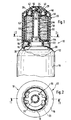
- the double-chamber container shown in FIGS. 1 and 2, designated in its entirety by 10, has a container 12 which is made of plastic by the blow molding process and which consists of two container chambers 16 arranged in a vertical superimposed position and integrally connected via a reduced-diameter passage 14 14, 18 composed.
- the passage duct 14, which is circular in diameter, thus represents the upper mouth of the lower container chamber 16 shown only in its upper region in FIG. 1 and an opening provided in the bottom of the upper container chamber 18, via which the two chambers 16 and 18 are therefore connected.
- the upper container chamber 18 is completely overlapped by a rotary cap 20, which is engaged by a locking cam 22 which engages under the upper container chamber 18 on the bottom side in the case illustrated in the drawing figures has the form of a circumferential annular projection projecting from the inner wall of the rotary cap 20, is rotatable, but is secured against being pulled off on the container chamber 18.
- a rotary cap 20 which is engaged by a locking cam 22 which engages under the upper container chamber 18 on the bottom side in the case illustrated in the drawing figures has the form of a circumferential annular projection projecting from the inner wall of the rotary cap 20, is rotatable, but is secured against being pulled off on the container chamber 18.
- two or more detent cams which protrude from the inner wall of the rotary cap 20 and are distributed at uniform angular intervals could of course also be provided in the form of individual projections.
- the transition area from the bottom to the peripheral wall of the upper container chamber 18 is formed into a circumferential, radially projecting annular bead 24, the outside diameter of which is approximately equal to the inside diameter of the rotary cap 20.
- the upper container chamber which runs out into a cylindrical orifice 26 of reduced diameter is sealed by an annular wall 28 which protrudes from the inner surface of the end wall of the rotary cap 20 and engages in the orifice 26 like a plug, which expediently has the shape of a so-called “sealing olive” indicated in FIG "Has, with its outer circumferential surface under slight prestress on the inner wall of the mouth 26, so that on the one hand obtain a reliable seal and on the other hand no noticeable resistance to rotation is built up when turning the rotary cap 20.
- the upper end of the application nozzle 32 engages in a cylindrical ring projection 40 projecting concentrically to the ring wall 28 from the inner surface of the rotary cap end wall, in the inner surface of which is connected to the end wall, an internal thread is formed, which is provided with a complementary external thread provided on the outer surface of the application nozzle 32 is engaged.
- FIG. 1 only one thread 42 can be seen from the internal thread of the ring projection, while the external thread of the application nozzle 32 is in the form of the projections 44, which are offset in height from one another on opposite sides and protrude radially from the outer surface of the application nozzle.
- the section of the application nozzle 32 directly adjoining the separating plug 30 is formed on the outside as a cylindrical sealing surface 46, which is assigned a complementary cylindrical sealing surface 48 in the free end region of the ring projection 40 facing away from the end wall.
- the end wall of the rotary cap 20 is weakened by an annular circumferential predetermined breaking notch 50 such that the part of the end wall lying within the predetermined breaking notch when the application nozzle is unscrewed by rotating the rotary cap 20 from the application nozzle the front wall is broken out.
- the broken-out end wall part thus forms, together with the closure pin 36, an optionally removable stopper closure for the application opening 34 of the application nozzle 32.
- the application nozzle 32 can actually be screwed out in the longitudinal direction of the container from the opening created by breaking out the end wall part to such an extent that the complementary sealing surfaces 46, 48 seal against one another. must be prevented that the application nozzle 32 and the separating plug 30 provided in one piece at its lower end can rotate with the rotary cap 20.
- the procedure is such that first the lower container chamber 16 of the container 12 is filled with the prescribed amount of the filling component 38, whereupon the separating plug 30 is pressed through the mouth 26 of the upper container chamber 18 into the passage channel 34 . Then the second filling component 56 is filled into the upper container chamber 18, whereupon the rotary cap 20 is snapped onto the upper container chamber 18. The ring wall 36 then seals in the mouth 26 of the upper container chamber 18 and the closure pin 36 closes the application opening 34 in the application nozzle.
- the preparation of the filling components 38 and 56 for the ready-to-use preparation is carried out in such a way that the rotary cap 20 is rotated in the sense of unscrewing the application nozzle 32.
- the complementary threads 42, 44 in the annular projection 40 or on the outside of the application nozzle 32 then cause the application nozzle 32 to be unscrewed, which with its free front end breaks out the part of the end wall of the rotary cap 20 lying within the predetermined breaking notch 50.
- the application nozzle 32 is then unscrewed from the opening formed in the end wall until the complementary sealing surfaces 46 on the separating plug end of the application nozzle 32 and 48 engage in the lower end region of the annular projection 40.
- the filling component 56 passes into the lower container chamber 16 and can be mixed with the filling component 38 by shaking to form the ready-to-use preparation. This preparation can then be applied directly via the application nozzle 32 after the closure pin 36 has been pulled out of the application opening 34 beforehand.
- the broken-off part of the end wall of the rotary cap located on the locking pin serves as a handle for pulling out the locking pin 36.
- FIGS. 3 to 6 expedient further developments are shown in relation to the double-chamber container 10 described in connection with FIGS. 1 and 2, which are described below. Only the modifications made are emphasized, while it is sufficient with regard to the basic structure of the double-chamber container to refer to the preceding description, especially since the same reference numerals are assigned to the same parts of both containers in the drawing.
- the essential changes concern the design of the rotary cap 20 in the area of the ring projection 40 and that in the closed position of the double-chamber container 10 within of the ring projection 40 is the free end of the application nozzle 32.
- the free end of the application nozzle 32 is unscrewed from the upper container chamber 16 by rotating the rotary cap, at the same time the separating plug 30 from the passage 14 between the upper and lower container chamber 16, 18th is pulled out.
- a mating thread 42 complementary to the external thread 44 of the application nozzle 32 is formed in the ring projection 40, on the other hand, as can be seen in FIG.
- the length of the application nozzle 32 is dimensioned such that it engages in the intended filled and closed position of the double-chamber container 10 to the inside of the ring projection 40 so that the beginning thread of the outer diameter 44 is still above the web 43. That is, when the rotary cap is installed by placing it vertically on the (filled) upper container chamber 16, the conically widening front end 33 of the application nozzle 32 first enters the annular projection 40 through the web 43 until the beginning thread of the external thread 44 abuts the web 43. When the rotary cap is pressed on further, the thread in the contact area deforms the web 43 in the manner indicated by dash-dotted lines in FIG.
- a thread of the mating thread to the external thread 44 then being formed from the originally radially circumferential web, that is to say when the thread is now in the intended position
- the closed position of the twisted cap 20 is turned in the screwing direction, the external thread 44 is screwed from the deformed web area into the ring projection 40 and the free front end 33 of the application nozzle 32 passes through the end wall of the rotary cap 20.
- the end wall has an opening 51 in the area lying above the annular projection 40, and this opening 51 is closed in the filled and closed position of the container 10 by the separate sealing plug 35 shown in FIG.
- a closure pin 36 fits appropriately into the application opening 34 of the application nozzle 32. The sealing pin 36 thus prevents - as long as the sealing plug 35 has not been removed - an escape of the filling component contained in the lower container chamber or - after unscrewing the application nozzle 32 - an escape of the preparation prepared from both filling components.
- the rotary cap 20 does not have to completely overlap the upper container chamber in the manner realized in the exemplary embodiment, but that in principle an embodiment can also be implemented in which the peripheral wall is shorter or lower, the rotatable but non-displaceable in the axial direction Holding the rotary cap 20 on the upper container chamber 18 is then formed by one or more protrusions or protrusions corresponding to the detent cam 22 or protrusions from the inside of the peripheral wall of the rotary cap can, which (r) is or are engaged in a circumferential annular groove-like depression in the wall of the upper container chamber 18.
Landscapes
- Engineering & Computer Science (AREA)
- Mechanical Engineering (AREA)
- Closures For Containers (AREA)
- Package Specialized In Special Use (AREA)
Abstract
Claims (15)
- Récipient à deux chambres (10) servant à recevoir deux composants séparés de remplissage, qui doivent être préparés avant le prélèvement à partir du récipient, pour former une préparation prête à être utilisée, et qui sont contenus dans deux chambres (16;18) du récipient superposées dans un boîtier du récipient, les chambres du récipient étant raccordées l'une à l'autre par l'intermédiaire d'un canal de passage (14), qui débouche dans la face supérieure de la chambre inférieure du récipient et dans la paroi inférieure de la chambre supérieure du récipient, ce canal étant fermé par un bouchon de séparation (30), qui peut être repoussé dans l'une des chambres (16;18) du récipient, par un poussoir pouvant être déplacé de l'extérieur dans la direction verticale, de sorte que les composants de remplissage peuvent s'écouler ensemble et se mélanger l'un l'autre.
caractérisé par le fait
que le poussoir est une buse allongée creuse d'application (32), qui est raccordée de façon fixe au bouchon de séparation (30) et s'étend à travers la chambre supérieure (18) du récipient jusque dans l'embouchure ouverte (26) de cette chambre et dont la cavité s'ouvre à son extrémité inférieure, à travers le bouchon de séparation (30), pour déboucher dans la chambre inférieure (16) du récipient et débouche, au niveau de l'extrémité supérieure,
dans une ouverture d'application (34), que le poussoir comporte, sur sa face extérieure, un filetage extérieur (44), qui engrène avec un filetage antagoniste complémentaire (42), qui est formé dans une partie saillante annulaire cylindrique (40) qui pénètre dans la face supérieure ouverte de la chambre supérieure (18) du récipient en faisant saillie à partir de la paroi frontale d'un capuchon rotatif (20) qui s'engage au moins partiellement par-dessus la chambre supérieure (18) du récipient, est maintenu de manière à pouvoir tourner sur cette chambre et la ferme de façon étanche,
que la partie, située à l'intérieur de la partie saillante annulaire (40), de la paroi frontale du capuchon rotatif (20) est agencée de telle sorte que, cette partie peut être repoussée par l'extrémité libre de la buse d'application (32), hors de la paroi frontale, lors de la rotation du capuchon rotatif (20) dans le sens d'un vissage de la buse d'application (32) dans la partie saillante annulaire (40),et que la section, qui se raccorde directement au bouchon de séparation (30), de la buse d'application (32) possède une surface extérieure d'étanchéité (46), qui, lorsque la buse d'application (32) est dans la position totalement ressortie par dévissage, s'applique de manière étanche contre une surface d'étanchéité complémentaire (48) formée sur la partie saillante annulaire (40). - Récipient selon la revendication 1, caractérisé en ce que sur le bouchon de séparation (30) d'une part et dans la chambre supérieure (18) du récipient d'autre part, il est prévu des dispositifs de butée qui coopèrent entre eux et empêchent un entraînement en rotation du bouchon de séparation (30) et de la buse d'application(32), qui est raccordée à ce bouchon, lors de la rotation du capuchon rotatif (20).
- Récipient selon la revendication 2, caractérisé en ce que les dispositifs de butée comportent au moins un appendice sensiblement radial (54), qui fait saillie à partir du bouchon de séparation (30) en direction de la paroi circonférentielle de la chambre supérieure (18) du récipient, et au moins une nervure (52), qui fait saillie vers l'intérieur à partir de la paroi circonférentielle de la chambre supérieure (18) du récipient et s'étend sensiblement sur toute la hauteur de cette chambre et contre laquelle s'applique l'appendice radial (54) du bouchon de séparation (30) lors d'un mouvement de rotation.
- Récipient selon l'une des revendications 1 à 3, caractérisé en ce que le récipient (12) est fabriqué d'un seul tenant en matière plastique au moyen du procédé de soufflage.
- Récipient selon l'une des revendications 1 à 4, caractérisé en ce que le capuchon rotatif (20) s'engage complètement par-dessus la chambre supérieure (18) du récipient et possède au niveau de son extrémité inférieure, au moins un ergot d'encliquetage (22), qui fait saillie radialement vers l'intérieur et s'engage au-dessous de la paroi inférieure de la chambre supérieure (18) du récipient.
- Récipient selon la revendication 5, caractérisé en ce que la chambre supérieure (18) du récipient possède, dans la zone de transition entre sa paroi inférieure et la paroi circonférentielle,un bourrelet annulaire périphérique (24) au-dessous duquel s'engage le ou les ergots d'encliquetage (22).
- Récipient selon l'une des revendications 1 à 6, caractérisé en ce que le capuchon rotatif (20) possède une paroi annulaire (28), qui à partir de la surface intérieure de la paroi frontale du capuchon pénètre dans l'embouchure (26) de la chambre supérieure (18) du récipient et établit une étanchéité à la manière d'un bouchon creux, dans cette embouchure.
- Récipient selon l'une des revendications 1 à 7, caractérisé en ce que le capuchon rotatif (20) est formé par moulage par injection d'une matière plastique et que la partie de la paroi frontale, qui peut être ressortie hors du capuchon rotatif (20) lors du dévissage de la buse d'application (32), est une partie intégrante de la paroi frontale du capuchon rotatif, qui est insérée dans une encoche circonférentielle annulaire de rupture de consigne (50).
- Récipient selon la revendication 8, caractérisé en ce qu'un téton de fermeture (36) s'étend, à partir de la surface intérieure, tournée vers la buse d'application (32), de la partie pouvant être ressortie hors de la paroi frontale du capuchon rotatif, dans l'ouverture d'application (34) de la buse d'application (32).
- Récipient selon l'une des revendications 1 à 9, caractérisé en ce que le bouchon de séparation (30) et la buse d'application (32) sont formés d'un seul tenant par moulage par injection d'une matière plastique.
- Récipient selon l'une des revendications 1 à 10, caractérisé en ce que la surface d'étanchéité extérieure (46), qui se raccorde directement au bouchon de séparation (30), de la buse d'application (32) et la surface d'étanchéité complémentaire (48) formée dans la partie saillante annulaire (40) du capuchon rotatif (20) sont essentiellement cylindriques, le diamètre de la surface d'étanchéité (46) formée sur la buse d'application (32) étant au moins égal et de préférence légèrement supérieur au diamètre intérieur de la surface d'étanchéité (48) formée dans la partie saillante annulaire (40).
- Récipient selon la revendication 1, caractérisé en ce que la buse d'application (32) possède, sur son extrémité tournée vers l'ouverture d'application,en avant de la section pourvue d'un filetage extérieur, une section (33) de forme rétrécie conique, en ce qu'une barrette circonférentielle radiale (43) fait saillie à partir de la paroi intérieure de la partie saillante annulaire (40) au point que le diamètre intérieur, qui subsiste à l'intérieur de la partie saillante annulaire (40) dans la zone de la barrette (43), est approximativement égal ou légèrement inférieur au diamètre du noyau du filetage extérieur (44) de la buse d'application (32), et en ce que la barrette (43) fait saillie, à partir de la paroi intérieure de la partie saillante annulaire (40), dans une zone située déjà au-dessous de la section conique sans filetage (33) de la buse d'application (32), lorsque le capuchon rotatif (20) est monté de façon correcte et que les chambres (16;18) du récipient sont fermées l'une par rapport à l'autre au moyen du bouchon de séparation (30).
- Récipient selon la revendication 12, caractérisé en ce que la paroi frontale du capuchon rotatif (20) possède, dans la zone de la partie saillante annulaire (40) prévue sur la face intérieure, un passage (51), et en ce que le passage (51) est fermé par un bouchon (35), qui peut être ressorti hors du passage (51) par l'extrémité libre de la buse d'application (32), lors du dévissage de cette dernière.
- Récipient selon la revendication 13, caractérisé en ce qu'un téton (36), qui pénètre dans l'ouverture d'application (34) de la buse d'application (32), fait saillie sur la surface intérieure du bouchon (35), qui est tournée vers la buse d'application(32).
- Récipient selon l'une des revendications 12 à 14, caractérisé en ce que la surface d'étanchéité (48), qui est complémentaire de la surface extérieure d'étanchéité (46) prévue sur le pied de la buse d'application (32), dans le capuchon rotatif (20), est formée par la face intérieure d'une seconde partie saillante annulaire (49), dont le diamètre est agrandi et qui fait saillie sur la face intérieure de la paroi frontale du capuchon rotatif (20).
Applications Claiming Priority (4)
| Application Number | Priority Date | Filing Date | Title |
|---|---|---|---|
| DE3812343 | 1988-04-14 | ||
| DE19883812343 DE3812343C2 (de) | 1988-04-14 | 1988-04-14 | Doppelkammer-Behälter |
| DE3837595A DE3837595A1 (de) | 1988-04-14 | 1988-11-05 | Doppelkammer-behaelter |
| DE3837595 | 1988-11-05 |
Publications (2)
| Publication Number | Publication Date |
|---|---|
| EP0364527A1 EP0364527A1 (fr) | 1990-04-25 |
| EP0364527B1 true EP0364527B1 (fr) | 1992-12-30 |
Family
ID=25866949
Family Applications (1)
| Application Number | Title | Priority Date | Filing Date |
|---|---|---|---|
| EP89903136A Expired - Lifetime EP0364527B1 (fr) | 1988-04-14 | 1989-02-20 | Recipient a deux cavites |
Country Status (5)
| Country | Link |
|---|---|
| US (1) | US5060791A (fr) |
| EP (1) | EP0364527B1 (fr) |
| JP (1) | JPH03500870A (fr) |
| DE (1) | DE3837595A1 (fr) |
| WO (1) | WO1989009736A1 (fr) |
Families Citing this family (40)
| Publication number | Priority date | Publication date | Assignee | Title |
|---|---|---|---|---|
| IT1259853B (it) * | 1992-12-09 | 1996-03-28 | Bernardino Parise | Contenitore per sostanze concentrate in polvere o liquide da porre in soluzione entro un involucro al momento dell'uso |
| DE4428575C1 (de) | 1994-08-12 | 1996-04-11 | Goldwell Gmbh | Mittel zur dauerhaften Verformung von menschlichen Haaren |
| US5848731A (en) * | 1996-05-01 | 1998-12-15 | Deering; Ron | Dispenser for personal materials |
| FR2751942B1 (fr) * | 1996-08-02 | 1998-09-11 | Oreal | Dispositif pour le stockage separe de deux composants leur melange et la distibution du melange |
| DE19847968A1 (de) * | 1998-10-17 | 2000-04-20 | Boehringer Ingelheim Pharma | Verschlußkappe und Behälter als Zweikammer-Kartusche für Vernebler zur Erzeugung von Aerosolen |
| JP2003164508A (ja) * | 2001-12-03 | 2003-06-10 | Taisei Kako Co Ltd | 輸液容器 |
| WO2004005154A1 (fr) * | 2002-07-04 | 2004-01-15 | They Limited | Dispositif pour distribuer une substance dans un recipient |
| US7000898B2 (en) * | 2003-12-09 | 2006-02-21 | Howard Tak Su Lim | Vertical shut-off valve |
| GB2417941A (en) * | 2004-09-10 | 2006-03-15 | They Ltd | Dispensing device for mixing two substances |
| US20070269560A1 (en) * | 2006-05-17 | 2007-11-22 | In Zone Brands, Inc. | Beverage Bottle Closure Having Cap, Cover, and Confection |
| US20080202951A1 (en) * | 2007-02-27 | 2008-08-28 | Mark William Landolt | Dispensing closure for a liquid container |
| US8875874B2 (en) | 2007-08-09 | 2014-11-04 | Biosphere Spirits, Llc | Multi-compartment mixing container and method of filling |
| US8104611B2 (en) | 2007-08-09 | 2012-01-31 | Helou Jr Elie | Mixing container and method of filling |
| EP2077132A1 (fr) | 2008-01-02 | 2009-07-08 | Boehringer Ingelheim Pharma GmbH & Co. KG | Dispositif distributeur, dispositif de stockage et procédé pour la distribution d'une formulation |
| US20090308889A1 (en) * | 2008-06-11 | 2009-12-17 | Frank Lindsay | Container system |
| EP2414560B1 (fr) | 2009-03-31 | 2013-10-23 | Boehringer Ingelheim International GmbH | Procédé de revêtement d'une surface d'un composant |
| JP5210961B2 (ja) * | 2009-04-30 | 2013-06-12 | 株式会社吉野工業所 | 混合容器 |
| EP2432531B1 (fr) | 2009-05-18 | 2019-03-06 | Boehringer Ingelheim International GmbH | Adaptateur, dispositif d'inhalation et pulvérisateur |
| JP5358295B2 (ja) * | 2009-05-29 | 2013-12-04 | 株式会社吉野工業所 | 注出容器 |
| WO2011064163A1 (fr) | 2009-11-25 | 2011-06-03 | Boehringer Ingelheim International Gmbh | Nébuliseur |
| MX2012005961A (es) | 2009-11-25 | 2012-06-14 | Boehringer Ingelheim Int | Nebulizador. |
| US10016568B2 (en) | 2009-11-25 | 2018-07-10 | Boehringer Ingelheim International Gmbh | Nebulizer |
| US20110290752A1 (en) * | 2010-05-27 | 2011-12-01 | Yeager Don F | Inverted bottle assembly |
| US8141700B2 (en) * | 2010-05-28 | 2012-03-27 | Tap the Cap, Inc. | Bottle cap for dispersing powdered supplement in situ |
| US8083055B2 (en) * | 2010-05-28 | 2011-12-27 | Tap the Cap, Inc. | Dispensing cap system for beverage bottles |
| EP2585151B1 (fr) | 2010-06-24 | 2018-04-04 | Boehringer Ingelheim International GmbH | Nébuliseur |
| USD672237S1 (en) | 2011-01-11 | 2012-12-11 | Tap the Cap, Inc. | Bottle cap for powdered supplement |
| WO2012130757A1 (fr) | 2011-04-01 | 2012-10-04 | Boehringer Ingelheim International Gmbh | Appareil médical pourvu d'un récipient |
| US9827384B2 (en) | 2011-05-23 | 2017-11-28 | Boehringer Ingelheim International Gmbh | Nebulizer |
| WO2013152894A1 (fr) | 2012-04-13 | 2013-10-17 | Boehringer Ingelheim International Gmbh | Pulvérisateur comprenant des moyens de détrompage |
| US8640865B2 (en) * | 2012-05-01 | 2014-02-04 | William Smart | Cap for storing materials separate from a body of liquid and facilitating subsequent mixing of the materials and the liquid |
| GB201222658D0 (en) * | 2012-12-14 | 2013-01-30 | Seabrook Crisps Ltd | Closure arrangements |
| JP6643231B2 (ja) | 2013-08-09 | 2020-02-12 | ベーリンガー インゲルハイム インターナショナル ゲゼルシャフト ミット ベシュレンクテル ハフツング | ネブライザ |
| EP2835146B1 (fr) | 2013-08-09 | 2020-09-30 | Boehringer Ingelheim International GmbH | Atomiseur |
| HUE058904T2 (hu) | 2014-05-07 | 2022-09-28 | Boehringer Ingelheim Int | Porlasztókészülék |
| US10722666B2 (en) | 2014-05-07 | 2020-07-28 | Boehringer Ingelheim International Gmbh | Nebulizer with axially movable and lockable container and indicator |
| CA2948071C (fr) | 2014-05-07 | 2022-08-30 | Boehringer Ingelheim International Gmbh | Contenant, nebuliseur et utilisation |
| US20180044069A1 (en) * | 2016-08-11 | 2018-02-15 | Rolando Perez | Solid and liquid dietary dispensing system |
| FR3110898B1 (fr) * | 2020-05-27 | 2024-03-15 | Coradin Sas | Ensemble compose d’un recipient pour un fluide et d’un emballage distributeur |
| US20240116014A1 (en) * | 2022-10-07 | 2024-04-11 | King's Flair Marketing Limited | Liquid dispensing apparatus for controllable mixing of liquids |
Family Cites Families (17)
| Publication number | Priority date | Publication date | Assignee | Title |
|---|---|---|---|---|
| CH365021A (de) * | 1957-09-16 | 1962-10-15 | Walter Dr Zauner | Behälter, insbesondere Tube oder Flasche |
| US3070093A (en) * | 1959-02-25 | 1962-12-25 | Stanley J Sarnoff | Medicament and diluent storing, mixing, and dispensing device |
| DE2200536A1 (de) * | 1972-01-07 | 1973-07-19 | Zeller Plastik Koehn Graebner | Einrichtung zur getrennten aufbewahrung zweier verschiedener stoffe |
| DE2339388A1 (de) * | 1973-08-03 | 1975-02-13 | Henkel & Cie Gmbh | Behaelterverschluss aus kunststoff mit mischeinrichtung |
| NL7413077A (nl) * | 1974-10-03 | 1976-04-06 | Leer Koninklijke Emballage | Houder met schroefdop. |
| FR2370650A1 (fr) * | 1976-11-15 | 1978-06-09 | Oreal | Recipient de conditionnement et de distribution comportant au stockage deux compartiments separes |
| DE2753737C2 (de) * | 1977-12-02 | 1984-04-19 | Wella Ag, 6100 Darmstadt | Behälter für zwei schüttbare Stoffe |
| DE3109921A1 (de) * | 1981-03-14 | 1982-09-23 | Wella Ag, 6100 Darmstadt | Zwei-komponenten-verpackung fuer schuettbare medien |
| US4465183A (en) * | 1982-07-19 | 1984-08-14 | Kao Soap Co., Ltd. | Two-part liquid container with breakable partition |
| FR2569666B1 (fr) * | 1984-08-29 | 1987-04-03 | Oreal | Dispositif permettant de conserver, separes l'un de l'autre, au moins deux produits et d'effectuer leur melange ulterieurement, notamment au moment de l'utilisation |
| DE3571961D1 (en) * | 1984-12-07 | 1989-09-07 | Simone Morel | Obturating device for tubes, flasks and other containers, the opening and closing of which are controlled by rotation |
| DE8502008U1 (de) * | 1985-01-26 | 1985-08-29 | Celamerck Gmbh & Co Kg, 6507 Ingelheim | Verschlußkappe für Zweikomponentenpackungen |
| DE3528525A1 (de) * | 1985-08-08 | 1987-02-19 | Goldwell Gmbh | Doppelkammer-behaelter |
| DE8606224U1 (de) * | 1986-03-07 | 1987-07-02 | Robert Finke KG, 5950 Finnentrop | Flaschen-Verschlußkappe für Zwei-Komponenten-Packungen |
| DE3631133A1 (de) * | 1986-09-12 | 1988-03-24 | Wella Ag | Mehrkammerbehaelter |
| DE8624488U1 (de) * | 1986-09-12 | 1988-01-14 | Wella Ag, 6100 Darmstadt | Mehrkammerbehälter |
| US4747517A (en) * | 1987-03-23 | 1988-05-31 | Minnesota Mining And Manufacturing Company | Dispenser for metering proportionate increments of polymerizable materials |
-
1988
- 1988-11-05 DE DE3837595A patent/DE3837595A1/de not_active Withdrawn
-
1989
- 1989-02-20 US US07/457,803 patent/US5060791A/en not_active Expired - Fee Related
- 1989-02-20 EP EP89903136A patent/EP0364527B1/fr not_active Expired - Lifetime
- 1989-02-20 WO PCT/EP1989/000155 patent/WO1989009736A1/fr not_active Ceased
- 1989-02-20 JP JP1502934A patent/JPH03500870A/ja active Pending
Also Published As
| Publication number | Publication date |
|---|---|
| WO1989009736A1 (fr) | 1989-10-19 |
| DE3837595A1 (de) | 1990-05-10 |
| JPH03500870A (ja) | 1991-02-28 |
| US5060791A (en) | 1991-10-29 |
| EP0364527A1 (fr) | 1990-04-25 |
Similar Documents
| Publication | Publication Date | Title |
|---|---|---|
| WO1989009736A1 (fr) | Recipient a deux cavites | |
| EP0298357B1 (fr) | Récipient à deux compartiments | |
| DE69303434T2 (de) | Behälter für pharmazeutische Produkte aus zwei gesonderten Komponenten, mit Mitteln zu deren Mischung und dosierter Ausgabe | |
| EP0806344B1 (fr) | Procédé de remplissage par son fond d'un distributeur de colle et distributeur de colle pour la mise en oeuvre du procédé | |
| DE69202650T2 (de) | Zwei-Flaschen-Verpackung zur getrennten Aufbewahrung von zwei Produkten, insbesondere flüssigen und zur Mischung derselben vor dem Gebrauch. | |
| DE69807577T2 (de) | Verpackung zum Vermischen von zwei Produkten unmittelbar vor Gebrauch | |
| DE69905163T2 (de) | Vorrichtung zum ausdrücken des inhalts aus einer deformierbaren tube | |
| DE4412041A1 (de) | Austragvorrichtung für fließfähige Medien, insbesondere für den Austrag in nur einem Hub | |
| DE29923938U1 (de) | Vorrichtung zum Austragen eines pastösen Zweikomponenten-Gemisches | |
| CH691677A5 (de) | Ausgusseinrichtung. | |
| CH715396A2 (de) | Befüllbare, auf einen Behälter aufschraubbare oder aufsetzbare Verschlusskappe mit Druckknopf zum Entleeren einer durch sie geformten Kapsel. | |
| EP3941851B1 (fr) | Système d'emballage et procédé pour préparations de produit à plusieurs composants | |
| DE3405065A1 (de) | Vorrichtung zum herstellen und verspruehen einer aus wenigstens zwei komponenten, z. b. fluessigkeiten, und einem treibgas bestehenden mischung | |
| DE69304500T2 (de) | Mischvorrichtung zum Lagern und zur Abgabe einer Mischung von zwei, von der Abgabe von einander getrennten, Produkten | |
| DE602005003940T2 (de) | Verteilvorrichtung für parfüm | |
| DE2215360A1 (de) | Behaelter mit sicherheitsverschluss | |
| DE29916436U1 (de) | Behälter-Verschluss mit Wirkstoff-Kammer | |
| EP0269068B1 (fr) | Emballage-aérosol | |
| DE3528525C2 (fr) | ||
| DE69228460T2 (de) | Behälter mit Befestigungsmittel für Ausgabevorrichtung | |
| DE3812343C2 (de) | Doppelkammer-Behälter | |
| EP4334041B1 (fr) | Distributeur de gouettes, distributeur de liquide et procédé de fabrication d'un distributeur de liquide | |
| DE3437574C2 (fr) | ||
| DE20013272U1 (de) | Zweikomponentenspender | |
| DE19652148A1 (de) | Behälter, insbesondere Flasche |
Legal Events
| Date | Code | Title | Description |
|---|---|---|---|
| PUAI | Public reference made under article 153(3) epc to a published international application that has entered the european phase |
Free format text: ORIGINAL CODE: 0009012 |
|
| AK | Designated contracting states |
Kind code of ref document: A1 Designated state(s): FR GB NL |
|
| 17P | Request for examination filed |
Effective date: 19891121 |
|
| RAP1 | Party data changed (applicant data changed or rights of an application transferred) |
Owner name: GOLDWELL AKTIENGESELLSCHAFT |
|
| 17Q | First examination report despatched |
Effective date: 19920525 |
|
| GRAA | (expected) grant |
Free format text: ORIGINAL CODE: 0009210 |
|
| AK | Designated contracting states |
Kind code of ref document: B1 Designated state(s): FR GB NL |
|
| ET | Fr: translation filed | ||
| GBT | Gb: translation of ep patent filed (gb section 77(6)(a)/1977) |
Effective date: 19930402 |
|
| PLBE | No opposition filed within time limit |
Free format text: ORIGINAL CODE: 0009261 |
|
| STAA | Information on the status of an ep patent application or granted ep patent |
Free format text: STATUS: NO OPPOSITION FILED WITHIN TIME LIMIT |
|
| 26N | No opposition filed | ||
| REG | Reference to a national code |
Ref country code: FR Ref legal event code: CJ Ref country code: FR Ref legal event code: CD |
|
| NLS | Nl: assignments of ep-patents |
Owner name: GOLDWELL GMBH |
|
| PGFP | Annual fee paid to national office [announced via postgrant information from national office to epo] |
Ref country code: NL Payment date: 19970227 Year of fee payment: 9 |
|
| PGFP | Annual fee paid to national office [announced via postgrant information from national office to epo] |
Ref country code: FR Payment date: 19980210 Year of fee payment: 10 |
|
| PGFP | Annual fee paid to national office [announced via postgrant information from national office to epo] |
Ref country code: GB Payment date: 19980211 Year of fee payment: 10 |
|
| PG25 | Lapsed in a contracting state [announced via postgrant information from national office to epo] |
Ref country code: NL Free format text: LAPSE BECAUSE OF NON-PAYMENT OF DUE FEES Effective date: 19980901 |
|
| NLV4 | Nl: lapsed or anulled due to non-payment of the annual fee |
Effective date: 19980901 |
|
| PG25 | Lapsed in a contracting state [announced via postgrant information from national office to epo] |
Ref country code: GB Free format text: LAPSE BECAUSE OF NON-PAYMENT OF DUE FEES Effective date: 19990220 |
|
| GBPC | Gb: european patent ceased through non-payment of renewal fee |
Effective date: 19990220 |
|
| PG25 | Lapsed in a contracting state [announced via postgrant information from national office to epo] |
Ref country code: FR Free format text: LAPSE BECAUSE OF NON-PAYMENT OF DUE FEES Effective date: 19991029 |
|
| REG | Reference to a national code |
Ref country code: FR Ref legal event code: ST |