EP0364558B1 - Systeme de communication de donnees et procede pour celui-ci - Google Patents
Systeme de communication de donnees et procede pour celui-ci Download PDFInfo
- Publication number
- EP0364558B1 EP0364558B1 EP89904413A EP89904413A EP0364558B1 EP 0364558 B1 EP0364558 B1 EP 0364558B1 EP 89904413 A EP89904413 A EP 89904413A EP 89904413 A EP89904413 A EP 89904413A EP 0364558 B1 EP0364558 B1 EP 0364558B1
- Authority
- EP
- European Patent Office
- Prior art keywords
- link control
- priority
- line
- data
- control devices
- Prior art date
- Legal status (The legal status is an assumption and is not a legal conclusion. Google has not performed a legal analysis and makes no representation as to the accuracy of the status listed.)
- Expired - Lifetime
Links
Images


Classifications
-
- G—PHYSICS
- G06—COMPUTING OR CALCULATING; COUNTING
- G06F—ELECTRIC DIGITAL DATA PROCESSING
- G06F11/00—Error detection; Error correction; Monitoring
- G06F11/07—Responding to the occurrence of a fault, e.g. fault tolerance
- G06F11/16—Error detection or correction of the data by redundancy in hardware
- G06F11/20—Error detection or correction of the data by redundancy in hardware using active fault-masking, e.g. by switching out faulty elements or by switching in spare elements
- G06F11/202—Error detection or correction of the data by redundancy in hardware using active fault-masking, e.g. by switching out faulty elements or by switching in spare elements where processing functionality is redundant
- G06F11/2038—Error detection or correction of the data by redundancy in hardware using active fault-masking, e.g. by switching out faulty elements or by switching in spare elements where processing functionality is redundant with a single idle spare processing component
-
- G—PHYSICS
- G06—COMPUTING OR CALCULATING; COUNTING
- G06F—ELECTRIC DIGITAL DATA PROCESSING
- G06F13/00—Interconnection of, or transfer of information or other signals between, memories, input/output devices or central processing units
- G06F13/14—Handling requests for interconnection or transfer
- G06F13/36—Handling requests for interconnection or transfer for access to common bus or bus system
-
- H—ELECTRICITY
- H04—ELECTRIC COMMUNICATION TECHNIQUE
- H04L—TRANSMISSION OF DIGITAL INFORMATION, e.g. TELEGRAPHIC COMMUNICATION
- H04L12/00—Data switching networks
- H04L12/28—Data switching networks characterised by path configuration, e.g. LAN [Local Area Networks] or WAN [Wide Area Networks]
- H04L12/40—Bus networks
- H04L12/403—Bus networks with centralised control, e.g. polling
Definitions
- This invention relates to data communications systems of the kind including a plurality of main terminals and a plurality of satellite terminals, said terminals being interconnected by a communications line.
- the invention also relates to a method for controlling the flow of data among a plurality of main terminals and a plurality of satellite terminals.
- the invention has a particular application to point of sale systems.
- POS terminals In the field of data processing, the use of point of sale (POS) terminals has required and also has enabled rapid and accurate transfer of information from one location to another in a business operation.
- the sales data In the case of department stores, the sales data may be transmitted or communicated from one or more terminals throughout the store to a central computer or processing unit.
- a filing system may be provided to maintain inventory and price data on the huge number of items that are sold in the store. The filing system and the control therefor provide means for reading and updating data and information regarding the constantly changing inventory and prices for the overall operation.
- U.S. Patent No. 4,468,750 discloses a point of sale system including a primary media terminal, a plurality of satellite terminals constructed and operated in a similar manner to the media terminal, and a backup media terminal.
- a diskette inserted into the primary media terminal received and stores data from the satellite terminals.
- the backup media terminal may be converted into the primary media terminal for the system by transferring the diskette from the faulty primary media terminal and inserting it into the the backup media terminal.
- the conversion of the backup media terminal to the primary media terminal is thus a relatively slow and cumbersome manual operation, and interrupts the normal operational usage of the system.
- the document US-A-4 596 012 discloses a data communications system, including a plurality of master stations and a plurality of slave stations interconnected by a communications line.
- Each master station contains a bus controller and a bus controller activator.
- the bus controller controls the transmission of data on the communications line.
- the bus controller activator monitors the state of the communications line in relation to data appearing thereon and in response to detecting that there is no bus activity transmits, after a random time schedule, a take control message to itself and to the other master stations. If other master stations transmit a take control message at the same time, messages will be garbled, bus activity is detected, a new random time schedule is generated and the process is repeated until only one master station transmits and receives its own take control message.
- the document US-A-4 456 956 discloses a computer network with a plurality of computer stations interconnected by a bus where access to the bus is controlled by the adapter unit of the computer station currently in charge. Control of the bus is continually passed from one live adapter to another. If the bus becomes inactive, all adapters detecting this enter election mode, where each adapter sends a pulse over the bus and monitors the bus for a period of time directly proportional to its unique number (priority). The winning adapter unit (the adapter unit with the lowest number) sends out another pulse and takes over the bus control, the other adapter units detecting said another pulse and becoming losers in the election.
- data communication system as defined in claim 1, including a plurality of main terminals and a plurality of satellite terminals, said terminals being interconnected by a communications line, wherein said main terminals include respective link control devices coupled to said communications line, said link control devices being of different priorities and one of said plurality of link control devices controlling data transmission and reception among said terminals in accordance with a request for data; each link control device including line controlling means adapted to control the transmission of data on said communications line from said satellite terminals in accordance with requests for data; and line monitoring means adapted to monitor the state of said communications line in relation to data appearing thereon, characterized in that each link control device further includes a confirmation requesting means and a priority judging means, said line monitoring means being adapted to supply a failure detection signal to the confirmation requesting means and the priority judging means in the same link control device in response to detecting an abnormality in said state of said communications line; said confirmation requesting means being adapted in response to said failure detection signal to transmit a priority request
- a method as defined in claim 6 for controlling in a data communication system for controlling in a data communication system according to claim 1 the flow of data among a plurality of main terminals and a plurality of satellite terminals over a communications line connecting said terminals, wherein said main terminals include respective link control devices of different priorities coupled to said communications line including the steps of: controlling data transmission and reception among said terminals in accordance with a request for data; and monitoring the condition of said line in accordance with data appearing on said line, characterized by the steps of: generating a failure detection signal in one of said link control devices upon detecting an abnormality in the condition on said communications line; applying said failure detection signal to confirmation requesting means and priority judging means in the same link control device which detected abnormality; sending a priority request signal to the other link control devices and, in response thereto, operating respective priority judging means in the other link control devices in response to said failure detection signal; determining the priority of said link control devices in response to said failure detection signal and said priority request signal, causing the link control device having the highest
- a data communications system has the advantage that an alternative link control device automatically controls the data communication when one link control device fails, without the need for a manual line switching operation, thereby increasing system reliability by reducing or avoiding system down time. Furthermore, the system is particularly suited to operation over a two-wire line or circuit, avoiding the complex line switching arrangements such as are associated with four-wire lines or circuits.
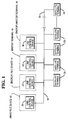
- Fig. 1 is a diagram showing a preferred embodiment of a POS system in which the link control system of the present invention is employed.
- a plurality of main terminals 12, 14, 16 and 18 are provided in the POS system.
- a plurality of link control devices 20, 22, 24 and 26 are respectively provided within the main terminals 12, 14, 16 and 18 of the POS system.
- the main terminals consist of and are described as a main file device 12, a backup file device 14, a master terminal 16, and a backup master terminal 18. It is not always neccessary to provide the link control devices 20, 22, 24 and 26 in all the respective main terminals 12, 14, 16 and 18 and the number of the link control devices can be increased or decreased as required. For example, it may not be necessary to provide a link control device in the backup master terminal 18.
- the link control devices 20, 22, 24 and 26 are different from one another in ranking of priority. Although the highest ranking of priority is generally offered to the link control device 20 in the main file device 12, the priority ranking can be appropriately changed as required. In the preferred embodiment, the ranking of priority follows the order of the link control devices from 20 to 22 to 24 to 26.
- the link control device 20 of the highest priority controls the data communication within the system.
- the link control device 20 polls a plurality of individual satellite terminals 28 in a predetermined cycle and receives/transmits data from/to a satellite terminal 28 from which a request to transmit/receive data is received. In general, the polling is performed on any one of the terminals 12, 14, 16 and 18 at a rate of one time per 100 milliseconds, so that as long as the link control device 20 is in the normal operation, data should appear on a two-wire line or circuit 30 at least one time per 100 milliseconds.
- the link control device 20 which performs the polling operation is referred to as a primary device.
- the receiving/transmitting of data by polling operation of the primary device 20 is well known in the art and hence the description thereof is omitted from this specification.
- the link control devices 22, 24 and 26 (each hereinafter referred to as a secondary device), other than the primary device 20, always monitor the line 30 to determine whether or not the primary device is in good order as well as responding to the polling from the primary device.
- Fig. 1 is a diagram of the link control system and Fig. 2 is a block diagram of the principle of the link control devices 20, 22, 24 and 26.
- a line controlling means 32 (Fig. 2) is provided for controlling the line 30 for polling operation of the primary device 20 or for responding to the polling from the primary device, as well as for responding to the polling from the secondary device.
- a confirmation requesting means 36 is provided for sending out a request to confirm the priority signal to the secondary devices 22, 24 and 26 when a line monitoring means 34 detects the failure of the line 30.
- a priority judging means 38 is provided for judging whether or not the device 20 can act as a primary device when the line monitoring means 34 detects the failure of the line 30 and a request to confirm the priority is made from a secondary device 22, 24 or 26.
- the line monitoring means 34 checks to see whether or not data appears on the line 30 within a predetermined period of time, for example, 500 milliseconds.
- the primary device 20 must poll any one of the terminals 14, 16, 18 or 28 (Fig. 1) at least one time per 100 milliseconds and hence data must appear on the line 30 at least one time per 100 milliseconds.
- no polling operation is performed, so that no data appears on the line 30 and hence the line monitoring means 34 detects the failure of the line.
- the line monitoring means 34 of such secondary device 24 will send a failure detection signal to the confirmation requesting means 36 and to the priority judging means 38.
- the confirmation requesting means 36 then sends a request to confirm the priority signal to the other secondary devices 22 and 26 via the line 30.
- the priority judging means 38 judges whether or not the secondary device of its own is at the highest ranking of priority among the now working secondary devices 22, 24 and 26.
- the secondary device 24 is at the priority ranking lower than that of the secondary device 22 and hence cannot act as the primary device.
- the secondary devices 22 and 26 receive the request to confirm the priority signal from the secondary device 24 by the line controlling means 32 (Fig. 2) of their own and send the signals thus received to the priority judging means 38 of their own which, then, judge the ranking of priority of their own simultaneously with the judging operation of the secondary device 24.
- the secondary device 26 cannot act as the primary device due to the presence of the secondary devices 22 and 24 at the higher ranking of priority.
- the priority judging means 38 of the secondary device 26 confirms that the secondary device 22 is at the highest ranking of priority to thus send a link control signal to the line controlling means 32.
- the line controlling means 32 receives the link control signal
- the secondary device 22 can act as the primary device to start the polling operation.
- Each of the link control devices 20, 22, 24 and 26 includes a central processing unit (CPU), a read only memory (ROM), a random access memory (RAM), and other necessary control circuits (not shown).
- Fig. 3 is a flow chart illustrating the restoring or recovering operation performed by the secondary device for the line control in case the primary device is down.
- the process steps in blocks 42, 44, 46 and 48 in Fig. 3 are steps for the operation of the line monitoring means 34 in Fig. 2.
- the process step in block 50 is for the operation of the confirmation controlling means 36
- the process steps in blocks 52, 54 and 56 are for the operation of the priority judging means 38
- the process steps in blocks 58 and 60 are for the operation of the line controlling means 32.
- Each of the link control devices 20, 22, 24 and 26 is constructed in the same manner except for their priority ranking. In view of this same construction, only the secondary device 24 will be described in detail.
- the secondary device 24 starts (block 40) a 500 millisecond timer (block 42) and then continually checks to see whether or not a request to confirm the priority is sent out from any of the remaining secondary devices 22 or 26 (block 44) and whether or not data appears on the line 30 (block 46).
- the secondary device 22 goes to the operation indicated in the process step represented by block 52.
- the secondary device 24 goes to the process step represented by block 48 to check whether or not the time of the 500 millisecond timer is timed out and, if not, returns to block 42 to repeat the same procedure.
- the polling operation is performed in a cycle shorter than 500 milliseconds, so that the data appears on the line 30 before the time of the 500 millisecond timer is timed out.
- the secondary device detects the appearance of the data on the line 30 in block 46, the process returns to block 42 to re-start the 500 millisecond timer to repeat the same procedures (blocks 42-48).
- the time of the 500 millisecond timer is timed out in block 48 and the secondary device 24 goes to block 50 wherein the request to confirm the priority signal is sent to the other secondary devices 22 and 26.
- the secondary device 24 goes to block 52 to start a 50 x n (a predetermined priority ranking of its own) millisecond timer and to check whether or not the data appears on the line 30 (block 54).
- the other secondary devices 22 and 26 receive the request to confirm the priority signals from the secondary device 24 in block 44 to start their 50 x n millisecond timers.
- the secondary devices 22, 24 and 26 check to see whether or not the times of the 50 x n millisecond timers are timed out (block 56).
- the link control device 20 when polled from the primary device 22, communicates with such primary device 22 to confirm the priority ranking of the primary device 22 (block 64) and to check whether device 20 is higher than the primary device 22 in priority ranking (block 66). Now, the link control device 20 is higher in priority ranking than the primary device 22, so that the primary device 22 transfers the right of primacy to the link control device 20, wherein the primary device 22 acts as the secondary device (block 68). If the link control device 20 is higher in priority, the link control device 20 acts as the primary device (block 70).
- the link control device 26 Even if the damaged link control device 26 has been restored after being repaired, the link control device 26 is lower in priority ranking than the primary device 22, so that device 26 acts as the secondary device. Accordingly, a link control device which is the highest in priority ranking of the link control devices under operation can control the line 30 of the overall system.
- the present invention is constructed such that a plurality of link control devices 20, 22, 24 and 26 are provided on a line or circuit 30 such that when one link control device is damaged, another link control device of the second or next priority ranking can automatically control the line 30.
- a stable link control system which requires no line switcher and which will not be down if a link control device is damaged can be constructed and maintained.
Landscapes
- Engineering & Computer Science (AREA)
- Theoretical Computer Science (AREA)
- Physics & Mathematics (AREA)
- General Engineering & Computer Science (AREA)
- General Physics & Mathematics (AREA)
- Quality & Reliability (AREA)
- Computer Networks & Wireless Communication (AREA)
- Signal Processing (AREA)
- Small-Scale Networks (AREA)
- Computer And Data Communications (AREA)
- Cash Registers Or Receiving Machines (AREA)
Abstract
Claims (7)
- Un système téléinformatique, comportant une pluralité de terminaux principaux (12, 14, 16, 18) et une pluralité de terminaux satellites (28), lesdits terminaux (12, 14, 16, 18, 28) étant interconnectés par une ligne téléinformatique (30), dans lequel lesdits terminaux principaux (12, 14, 16, 18) comportent des dispositifs de commande de liaison respectifs (20, 22, 24, 26) accouplés à ladite ligne téléinformatique (30), lesdits dispositifs de commande de liaison (20, 22, 24, 26) ayant des priorités différentes et un de ladite pluralité de dispositifs de commande de liaison (20, 22, 24, 26) commandant la transmission et la réception des données parmi lesdits terminaux (12, 14, 16, 18, 28) conformément à une demande de données; chaque dispositif de commande de liaison (par ex. 20) comportant un moyen de commande de ligne (32) adapté pour commander la transmission des données sur ladite ligne téléinformatique (30) à partir desdits terminaux satellites (28) conformément aux demandes de données; et un moyen de suivi de ligne (34) adapté pour assurer le suivi de l'état de ladite ligne téléinformatique (30) en ce qui concerne les données apparaissant sur cette dernière, caractérisé en ce que chaque dispositif de commande de liaison (par ex. 20) comporte, de plus, un moyen de demande de confirmation (36) et un moyen de jugement de priorité (38), ledit moyen de suivi de ligne (34) étant adapté pour fournir un signal de détection de défaillance au moyen de demande de confirmation (36) et au moyen de jugement de priorité (38) dans le même dispositif de commande de liaison en réponse à la détection d'une anomalie dans ledit état de ladite ligne téléinformatique (30); ledit moyen de demande de confirmation (36) étant adapté en réponse audit signal de détection de défaillance pour transmettre un signal de demande de priorité aux autres dispositifs de commande de liaison (par ex. 22, 24, 26); le moyen de jugement de priorité (38) déterminant une priorité en réponse audit signal de détection de défaillance issu de son moyen de suivi de ligne (34) ou à un signal de demande de priorité issu d'un autre dispositif de commande de liaison (par ex. 22, 24, 26) de façon à ce qu'un signal de commande de liaison soit envoyé par le moyen de jugement de priorité du dispositif de commande de liaison qui a la plus grande priorité audit moyen de commande de ligne (32) du dispositif de commande de liaison (20, 22, 24, 26) qui a la plus grande priorité, par quoi ledit moyen de commande de ligne (32) du dispositif de commande de liaison qui a la plus grande priorité assume la commande de la transmission de données sur ladite ligne téléinformatique (30) à partir desdits terminaux satellites (28), le moyen de suivi de ligne (34) des autres dispositifs de commande de liaison (20, 22, 24, 26) reprenant le suivi de l'état de ladite ligne téléinformatique (30) à la détection des données sur ladite ligne téléinformatique.
- Un système téléinformatique conformément à la revendication 1, caractérisé en ce que l'un desdits dispositifs de commande de liaison (par ex. 20) sert de dispositif primaire étant donné qu'il a une plus grande priorité que les autres dispositifs de commande de liaison (par ex. 22, 24, 26).
- Un système téléinformatique conformément à la revendication 1, caractérisé en ce que l'un desdits dispositifs de commande de liaison (par ex. 22) ayant une priorité moins grande sert de dispositif primaire lorsqu'un dispositif de commande de liaison (par ex. 20) ayant une plus grande priorité est inopérant.
- Un système téléinformatique conformément à la revendication 1, caractérisé par un moyen de temporisation associé de façon opérante à chacun des dispositifs de commande de liaison (20, 22, 24, 26), le temps étant réglé pour s'écouler conformément aux priorités respectives.
- Un système téléinformatique conformément l'une quelconque des revendications précédentes, caractérisé en ce que ledit système est un système point de vente et en ce que lesdits terminaux principaux (12, 14, 16, 18) comportent un dispositif de fichier (12) et un terminal maître (16) pour ledit système point de vente.
- Une méthode pour commander dans un système téléinformatique conformément à la revendication 1 le flux de données parmi une pluralité de terminaux principaux (12, 14, 16, 18) et une pluralité de terminaux satellites (28) sur une ligne téléinformatique (30) connectant lesdits terminaux (12, 14, 16, 18, 28), en quoi lesdits terminaux principaux comportent des dispositifs de commande de liaison respectifs (20, 22, 24, 26), ayant des priorités différentes, accouplés à ladite ligne téléinformatique, comportant les étapes de: la commande de la transmission et de la réception des données parmi lesdits terminaux (12, 14, 16, 18, 28) conformément à une demande de données; et le suivi de l'état de ladite ligne (30) conformément aux données apparaissant sur ladite ligne (30), caractérisé par les étapes de: la génération d'un signal de détection de défaillance dans l'un desdits dispositifs de commande de liaison (20, 22, 24, 26) à la détection d'une anomalie au niveau de l'état sur ladite ligne téléinformatique (30); l'application dudit signal de détection de défaillance au moyen de demande de confirmation (36) et au moyen de jugement de priorité (38) dans le même dispositif de commande de liaison qui a détecté l'anomalie; l'envoi d'un signal de demande de priorité aux autres dispositifs de commande de liaison (22, 24, 26) et, en réponse à ce dernier, la mise en oeuvre des moyens de jugement de priorité respectifs (38) dans les autres dispositifs de commande de liaison (20, 22, 24, 26) en réponse audit signal de détection de défaillance; la détermination de la priorité desdits dispositifs de commande de liaison (20, 22, 24, 26) en réponse audit signal de détection de défaillance et audit signal de demande de priorité, faisant en sorte que le dispositif de commande de liaison (20, 22, 24, 26) ayant la plus grande priorité assume la commande de la transmission de données sur ladite ligne téléinformatique (30); et le retour des autres dispositifs de commande de liaison (20, 22, 24, 26) au suivi de l'état de ladite ligne téléinformatique (30).
- Une méthode conformément à la revendication 6, caractérisée en ce que ladite étape de détermination de la priorité desdits dispositifs de commande de liaison (20, 22, 24, 26) est réalisée à l'aide d'opérations de temporisation respectives pour lesdits dispositifs de commande de liaison (20, 22, 24, 26).
Applications Claiming Priority (4)
| Application Number | Priority Date | Filing Date | Title |
|---|---|---|---|
| JP63069963A JPH01256843A (ja) | 1988-03-25 | 1988-03-25 | リンク・コントロール・システム |
| JP69963/88 | 1988-03-25 | ||
| US316270 | 1989-02-27 | ||
| PCT/US1989/000991 WO1989009443A1 (fr) | 1988-03-25 | 1989-03-13 | Systeme de communication de donnees |
Publications (2)
| Publication Number | Publication Date |
|---|---|
| EP0364558A1 EP0364558A1 (fr) | 1990-04-25 |
| EP0364558B1 true EP0364558B1 (fr) | 1994-10-12 |
Family
ID=13417817
Family Applications (1)
| Application Number | Title | Priority Date | Filing Date |
|---|---|---|---|
| EP89904413A Expired - Lifetime EP0364558B1 (fr) | 1988-03-25 | 1989-03-13 | Systeme de communication de donnees et procede pour celui-ci |
Country Status (4)
| Country | Link |
|---|---|
| US (1) | US5058057A (fr) |
| EP (1) | EP0364558B1 (fr) |
| JP (1) | JPH01256843A (fr) |
| WO (1) | WO1989009443A1 (fr) |
Families Citing this family (10)
| Publication number | Priority date | Publication date | Assignee | Title |
|---|---|---|---|---|
| US5289578A (en) * | 1990-11-09 | 1994-02-22 | Foreign Exchange Transaction Services, Inc. | Activation of a dormant sibling computer in a communication network by overriding a unique dormant node address with a common active node address |
| JP2573747B2 (ja) * | 1990-12-19 | 1997-01-22 | 株式会社テック | 商品販売データ処理装置 |
| US5751220A (en) * | 1995-07-14 | 1998-05-12 | Sensormatic Electronics Corporation | Synchronized network of electronic devices including back-up master units |
| US6298376B1 (en) * | 1997-03-07 | 2001-10-02 | General Electric Company | Fault tolerant communication monitor for a master/slave system |
| JP2001229097A (ja) * | 2000-02-18 | 2001-08-24 | Fujitsu Ltd | 分散処理システム及びクライアント |
| KR100620289B1 (ko) | 2000-07-25 | 2006-09-07 | 삼성전자주식회사 | 마스터 이탈시 사설 간이 네트워크 운영 방법 |
| US7225356B2 (en) * | 2003-11-06 | 2007-05-29 | Siemens Medical Solutions Health Services Corporation | System for managing operational failure occurrences in processing devices |
| CN106612253B (zh) * | 2015-10-23 | 2019-10-22 | 中国科学院声学研究所 | 一种联动控制权管理装置及方法 |
| US12437304B2 (en) | 2022-03-23 | 2025-10-07 | Bank Of America Corporation | Intelligent coordination of transaction processing in a multi-device network |
| US20230306404A1 (en) * | 2022-03-23 | 2023-09-28 | Bank Of America Corporation | Dynamic Selection of Processing Devices in a Multi-Device Network |
Family Cites Families (13)
| Publication number | Priority date | Publication date | Assignee | Title |
|---|---|---|---|---|
| US3886524A (en) * | 1973-10-18 | 1975-05-27 | Texas Instruments Inc | Asynchronous communication bus |
| US4228496A (en) * | 1976-09-07 | 1980-10-14 | Tandem Computers Incorporated | Multiprocessor system |
| JPS5372403A (en) * | 1976-12-10 | 1978-06-27 | Hitachi Ltd | Loop communication system |
| US4266271A (en) * | 1978-10-10 | 1981-05-05 | Chamoff Martin E | Reconfigurable cluster of data-entry terminals |
| US4366653A (en) * | 1979-02-01 | 1983-01-04 | Bonnard & Gardel, Ingenieurs-Conseils Sa | Locking device for a cylindrical cavity |
| JPS56108103A (en) * | 1980-01-31 | 1981-08-27 | Toshiba Corp | Data transmission system of digital control device |
| US4320467A (en) * | 1980-02-25 | 1982-03-16 | Raytheon Company | Method and apparatus of bus arbitration using comparison of composite signals with device signals to determine device priority |
| JPS5715548A (en) * | 1980-07-02 | 1982-01-26 | Fujitsu Ltd | Polling monitor system |
| JPS57197642A (en) * | 1981-05-29 | 1982-12-03 | Sharp Corp | Information transmitting system |
| US4456956A (en) * | 1981-08-24 | 1984-06-26 | Data General Corp. | Method and apparatus for controlling access of a network transmission bus between a plurality of spaced apart computer stations |
| US4596012A (en) * | 1983-05-25 | 1986-06-17 | Reed Lockwood W | Master controller succession system for bus control access for data-communications local area networks |
| US4626844A (en) * | 1983-11-23 | 1986-12-02 | Indiana Cash Drawer Company | Addressable electronic switch |
| JPS61156368A (ja) * | 1984-12-27 | 1986-07-16 | Fujitsu Ltd | テ−ブル内容変更制御方式 |
-
1988
- 1988-03-25 JP JP63069963A patent/JPH01256843A/ja active Pending
-
1989
- 1989-02-27 US US07/316,270 patent/US5058057A/en not_active Expired - Fee Related
- 1989-03-13 WO PCT/US1989/000991 patent/WO1989009443A1/fr not_active Ceased
- 1989-03-13 EP EP89904413A patent/EP0364558B1/fr not_active Expired - Lifetime
Also Published As
| Publication number | Publication date |
|---|---|
| EP0364558A1 (fr) | 1990-04-25 |
| WO1989009443A1 (fr) | 1989-10-05 |
| US5058057A (en) | 1991-10-15 |
| JPH01256843A (ja) | 1989-10-13 |
Similar Documents
| Publication | Publication Date | Title |
|---|---|---|
| JP3108393B2 (ja) | Plcを用いた制御システム | |
| US5455959A (en) | System for collecting from masters information independently collected from associated slaves in shelves of a telecommunications terminal | |
| EP0050451B1 (fr) | Système de concentration et de collection pour données d'alarme | |
| EP0364558B1 (fr) | Systeme de communication de donnees et procede pour celui-ci | |
| JPH03230638A (ja) | 多重通信制御装置 | |
| US5835370A (en) | Network having a control device and a plurality of slave devices and communication method using the same network | |
| GB2198018A (en) | Simultaneous data communication | |
| WO1991014324A1 (fr) | Procede et systeme de communication pour l'echange seriel de donnees binaires | |
| JPH06101732B2 (ja) | 通信制御方式 | |
| JPS5992651A (ja) | ポ−リング方式 | |
| JP2930771B2 (ja) | 無線によるデータ収集方法 | |
| US5323145A (en) | Alarm collection architecture with redundant bus | |
| JPS58213548A (ja) | ボ−リング伝送方式 | |
| KR100394553B1 (ko) | 아이피씨시스템에서특정프로세서에대한재시동장치및방법 | |
| JP2000040013A (ja) | 二重化通信システムの回線異常検出方法 | |
| JP3294256B2 (ja) | データ通信方法及び装置 | |
| KR100229434B1 (ko) | 이중화 데이터 통신 제어 장치 | |
| JPH0644763B2 (ja) | デ−タ転送方式 | |
| JPH0638603B2 (ja) | 通信回線スケジューリング装置 | |
| JPH04240946A (ja) | データ通信システム | |
| JPS5946144B2 (ja) | デ−タ伝送装置 | |
| JP2723266B2 (ja) | ファクシミリシステム | |
| JPS6225531A (ja) | ル−プデ−タリンクシステムのモニタ方法 | |
| JPH0537531A (ja) | 親局バツクアツプ方式 | |
| JPS63138830A (ja) | 端末装置 |
Legal Events
| Date | Code | Title | Description |
|---|---|---|---|
| PUAI | Public reference made under article 153(3) epc to a published international application that has entered the european phase |
Free format text: ORIGINAL CODE: 0009012 |
|
| AK | Designated contracting states |
Kind code of ref document: A1 Designated state(s): DE FR GB |
|
| 17P | Request for examination filed |
Effective date: 19900331 |
|
| 17Q | First examination report despatched |
Effective date: 19920813 |
|
| RAP1 | Party data changed (applicant data changed or rights of an application transferred) |
Owner name: NCR INTERNATIONAL INC. |
|
| GRAA | (expected) grant |
Free format text: ORIGINAL CODE: 0009210 |
|
| RAP1 | Party data changed (applicant data changed or rights of an application transferred) |
Owner name: AT&T GLOBAL INFORMATION SOLUTIONS INTERNATIONAL IN |
|
| AK | Designated contracting states |
Kind code of ref document: B1 Designated state(s): DE FR GB |
|
| REF | Corresponds to: |
Ref document number: 68918795 Country of ref document: DE Date of ref document: 19941117 |
|
| ET | Fr: translation filed | ||
| PLBE | No opposition filed within time limit |
Free format text: ORIGINAL CODE: 0009261 |
|
| STAA | Information on the status of an ep patent application or granted ep patent |
Free format text: STATUS: NO OPPOSITION FILED WITHIN TIME LIMIT |
|
| 26N | No opposition filed | ||
| REG | Reference to a national code |
Ref country code: FR Ref legal event code: CD |
|
| PGFP | Annual fee paid to national office [announced via postgrant information from national office to epo] |
Ref country code: FR Payment date: 19990112 Year of fee payment: 11 |
|
| PGFP | Annual fee paid to national office [announced via postgrant information from national office to epo] |
Ref country code: GB Payment date: 19990226 Year of fee payment: 11 |
|
| PGFP | Annual fee paid to national office [announced via postgrant information from national office to epo] |
Ref country code: DE Payment date: 19991214 Year of fee payment: 11 |
|
| PG25 | Lapsed in a contracting state [announced via postgrant information from national office to epo] |
Ref country code: GB Free format text: LAPSE BECAUSE OF NON-PAYMENT OF DUE FEES Effective date: 20000313 |
|
| GBPC | Gb: european patent ceased through non-payment of renewal fee |
Effective date: 20000313 |
|
| PG25 | Lapsed in a contracting state [announced via postgrant information from national office to epo] |
Ref country code: FR Free format text: LAPSE BECAUSE OF NON-PAYMENT OF DUE FEES Effective date: 20001130 |
|
| REG | Reference to a national code |
Ref country code: FR Ref legal event code: ST |
|
| PG25 | Lapsed in a contracting state [announced via postgrant information from national office to epo] |
Ref country code: DE Free format text: LAPSE BECAUSE OF NON-PAYMENT OF DUE FEES Effective date: 20010103 |