EP0364603B1 - Soupape pilote hydraulique - Google Patents
Soupape pilote hydraulique Download PDFInfo
- Publication number
- EP0364603B1 EP0364603B1 EP89904218A EP89904218A EP0364603B1 EP 0364603 B1 EP0364603 B1 EP 0364603B1 EP 89904218 A EP89904218 A EP 89904218A EP 89904218 A EP89904218 A EP 89904218A EP 0364603 B1 EP0364603 B1 EP 0364603B1
- Authority
- EP
- European Patent Office
- Prior art keywords
- valve
- pistons
- damper
- valve body
- pilot
- Prior art date
- Legal status (The legal status is an assumption and is not a legal conclusion. Google has not performed a legal analysis and makes no representation as to the accuracy of the status listed.)
- Expired - Lifetime
Links
- 239000012530 fluid Substances 0.000 claims description 38
- 230000006835 compression Effects 0.000 claims description 18
- 238000007906 compression Methods 0.000 claims description 18
- 238000013016 damping Methods 0.000 abstract 1
- 125000006850 spacer group Chemical group 0.000 description 2
- 238000010276 construction Methods 0.000 description 1
Images


Classifications
-
- F—MECHANICAL ENGINEERING; LIGHTING; HEATING; WEAPONS; BLASTING
- F16—ENGINEERING ELEMENTS AND UNITS; GENERAL MEASURES FOR PRODUCING AND MAINTAINING EFFECTIVE FUNCTIONING OF MACHINES OR INSTALLATIONS; THERMAL INSULATION IN GENERAL
- F16K—VALVES; TAPS; COCKS; ACTUATING-FLOATS; DEVICES FOR VENTING OR AERATING
- F16K31/00—Actuating devices; Operating means; Releasing devices
- F16K31/44—Mechanical actuating means
-
- F—MECHANICAL ENGINEERING; LIGHTING; HEATING; WEAPONS; BLASTING
- F15—FLUID-PRESSURE ACTUATORS; HYDRAULICS OR PNEUMATICS IN GENERAL
- F15B—SYSTEMS ACTING BY MEANS OF FLUIDS IN GENERAL; FLUID-PRESSURE ACTUATORS, e.g. SERVOMOTORS; DETAILS OF FLUID-PRESSURE SYSTEMS, NOT OTHERWISE PROVIDED FOR
- F15B13/00—Details of servomotor systems ; Valves for servomotor systems
- F15B13/02—Fluid distribution or supply devices characterised by their adaptation to the control of servomotors
- F15B13/04—Fluid distribution or supply devices characterised by their adaptation to the control of servomotors for use with a single servomotor
- F15B13/042—Fluid distribution or supply devices characterised by their adaptation to the control of servomotors for use with a single servomotor operated by fluid pressure
- F15B13/0422—Fluid distribution or supply devices characterised by their adaptation to the control of servomotors for use with a single servomotor operated by fluid pressure with manually-operated pilot valves, e.g. joysticks
-
- Y—GENERAL TAGGING OF NEW TECHNOLOGICAL DEVELOPMENTS; GENERAL TAGGING OF CROSS-SECTIONAL TECHNOLOGIES SPANNING OVER SEVERAL SECTIONS OF THE IPC; TECHNICAL SUBJECTS COVERED BY FORMER USPC CROSS-REFERENCE ART COLLECTIONS [XRACs] AND DIGESTS
- Y10—TECHNICAL SUBJECTS COVERED BY FORMER USPC
- Y10T—TECHNICAL SUBJECTS COVERED BY FORMER US CLASSIFICATION
- Y10T137/00—Fluid handling
- Y10T137/8593—Systems
- Y10T137/87056—With selective motion for plural valve actuator
- Y10T137/87064—Oppositely movable cam surfaces
-
- Y—GENERAL TAGGING OF NEW TECHNOLOGICAL DEVELOPMENTS; GENERAL TAGGING OF CROSS-SECTIONAL TECHNOLOGIES SPANNING OVER SEVERAL SECTIONS OF THE IPC; TECHNICAL SUBJECTS COVERED BY FORMER USPC CROSS-REFERENCE ART COLLECTIONS [XRACs] AND DIGESTS
- Y10—TECHNICAL SUBJECTS COVERED BY FORMER USPC
- Y10T—TECHNICAL SUBJECTS COVERED BY FORMER US CLASSIFICATION
- Y10T137/00—Fluid handling
- Y10T137/8593—Systems
- Y10T137/87169—Supply and exhaust
- Y10T137/87233—Biased exhaust valve
Definitions
- the invention relates to a hydraulic pilot valve comprising
- the invention particularly refers to a hydraulic pilot valve for supplying pilot fluid under pressure into a pilot fluid actuated type switch-over valve or the like adapted to be actuated for switch-over by pilot fluid under pressure, and more particularly to a hydraulic pilot valve arranged to control the discharge rate of pilot fluid under pressure in proportion to the stroke of an operating lever.
- this valve has a valve body 1 having a plurality of axially extending valve holes 2 formed within the valve body 1 along the circumference of the latter, and a valve spool 3 slidably mounted in each of these valve holes 2.
- Each of the valve spools 3 has formed therein a radial hole 4 for pressurized fluid which opens in a small diameter portion 3a formed on the approximately intermediate axial portion therof, and an axial hole 5 for pressurized fluid, one end of which communicates with the radial hole 4 and the other end of which opens in the base end surface 3b of the valve spool.
- the valve body 1 has further formed axially in turn therein pilot pressurized fluid outlet ports 6, an inlet port 8, and a reservoir port 10, all of which are communicated with each other through the valve holes 2.
- the inlet port 8 communicates with a pilot pressurized fluid supply pump 7, and the reservoir port 10 communicates with a fluid reservoir 9.
- Pistons 11 are axially slidably mounted in the upper part of the valve body 1 at positions opposite to the valve spools 3 which are inserted in the above-mentioned plurality of valve holes 22, respectively.
- the upper end of each of the pistons 11 is biased against and kept in contact with the lower end surface of a pusher member 20 projecting from the valve body 1 and which is connected to an operating lever 18, by the resiliency of a spring 16.
- Each valve spool 3 is slidably inserted in each of the valve holes 2 in such a manner that the base end surface 3b thereof faces the corresponding outlet port 6, and the leading end portion 3c thereof is fitted in a blind hole 12 formed in the base end of each of the pistons 11.
- the arrangement is made such that when the operating lever 18 is tilted in the direction shown by arrow each of the valve spools 3 is allowed to slidably move down in the drawing through the respective piston 11 and spring 16 against the resilient force of a spring 14.
- valve spools 3 The downward sliding movement of the valve spools 3 allows the pilot fluid under pressure which is supplied by the pump 7 into the inlet port 7 to flow through the holes 4 and 5 formed in each of the valve spools 3 into the respective outlet port 6.
- the discharge rate of the pilot fluid under pressure which is allowed to flow into the outlet ports 6 is usually controlled in such a way as to increase in proportion to the stroke of the operating lever as shown, for example, by solid line in Fig. 3.
- the valve spools 3 are slidably moved down in the same manner through the springs 16 in accordance with the movement downward sliding movement in the drawing) of the pistons 11. Therefore, when the operating lever 18 is tilted suddenly, the pistons 11 are slidably moved down quickly so as to deflect the springs 16 quickly.
- the present invention has been made in view of the above-mentioned circumstances, and has for its object to provide a hydraulic pilot valve unit wherein valve spools for controlling the discharge rate of pilot fluid under pressure are moved accurately in accordance with the operation of an operating lever, and the discharge rate of pilot fluid under pressure can be varied in proportion to the stroke of the operating lever irrespective of the operating speed of the operating lever.
- the above-mentioned object is achieved by a hydraulic pilot valve of the above kind, characterized by
- the hydraulic pilot valve unit incorporating the above-mentioned aspect has the following advantages.
- the damper pistons are each kept continuously in contact with one end face of each of the valve spools so that the damper orifices may be kept closed. Subsequently, when the pistons are moved again by means of the operating lever, a damper effect is created in the damper chambers so that the valve spools may be moved smoothly to their second positions without any time delay in the same manner as mentioned above.
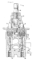
- the hydraulic pilot valve unit comprises a valve body 21 having a plurality of axially extending valve holes 22 formed within the valve body in the circumferential direction thereof, and a valve spool 23 is slidably mounted in each of the valve holes 22.
- Each of the valve spools 23 has formed therein a radial hole 24 for pressurized fluid which opens in a small diameter portion 23a formed on the approximately intermediate axial portion thereof, and an axial hole 25 for pressurized fluid, one end of which communicates with the radial hole 24 and the other end of which opens in the base end surface of the valve spool.
- the valve body 21 has further formed axially in turn therein pilot pressurized fluid outlet ports 26, an inlet port 28 and a reservoir port 30, all of which are communicated with each other through the valve holes 22.
- the inlet port 28 communicates with a pilot pressurized fluid supply pump 27, and the reservoir port 30 communicates with a fluid reservoir 29.
- Pistons 31 are axially slidably mounted in the upper part of the valve body 21 at positions opposite to the valve spools 23 which are inserted in the above-mentioned valve holes 22, respectively.
- the upper end of each of the pistons 31 is biased against and kept in contact with the lower end surface of a pusher member 40 projecting from the valve body 21 and which is connected to an operating lever 38, by the resiliency of a first compression spring 34.
- Each valve spool 23 is slidably inserted in each of the valve holes 22 in such a manner that the base end face 23b thereof faces the corresponding outlet port 26, and the leading end portion 23c thereof is fitted in a blind hole 32 formed in the base end 31a of each of the pistons 31.
- the arrangement is made such that when the operating lever 38 is tilted in the direction shown by arrow each of the valve spools 23 is allowed to slidably move down in the drawing to a first position through the respective piston 31 and first compression spring 34 end against the resilient force of a second compression spring 36.
- each of the first springs 34 is mounted between a spring retainer 33 of the piston 31 and the valve body 1 so as to bias normally each of the pistons 31 towards the pusher member 40.
- Each of the above-mentioned pistons 31 has a cylinder hole 32 formed therein in the shape of a blind hole and which is perforated to open into the reservoir port 30.
- a damper piston 41 is inserted in the cylinder hole 32 so as to define a damper chamber 42.
- the damper piston 21 has a narrow axially extending passage (or damper orifice) 43 formed in the approximately central part thereof so that the damper chamber 42 may be communicated with the reservoir port 30. Since the damper piston 41 is normally biased outwardly by a third compression spring 44 mounted within the damper chamber so as to abut against the leading end face of the valve spool 23, the damper orifice 43 is normally blocked by the leading end face 23d.
- one end face 31a of the piston 31 is abutted through a spring retainer 33 and a spacer 35 located thereunder against a first compression spring 34.
- a second compression spring 36 is moutned between the spring retainer 33 and a shoulder formed in the intermediate portion of the valve spool 23 so as to bias the valve spool 23 to a predetermined position so that the leading end 23c thereof may be abutted against the spacer 35 thereby holding the valve spool 23 at a second position; that is; a draining position, where the inlet port 28 is communicated through the holes 25 and 24 with the reservoir port 30.
- the above-mentioned valve body 21 has a mounting rod 37 screwed in the upper part thereof.
- an operating lever 38 is connected through a cross joint 39 to the mounting rod 37 so that it may be swung freely to the front and rear and to the left and right.
- a pusher member 40 mounted on the cross joint 39 is abutted against the above-mentioned pistons 31.
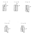
- the above-mentioned damper piston 41 may be formed in any of shapes as shown in Figs. 4A to 4E. In brief, it is only necessary to form the piston 41 in such a manner that the damper orifice 43 can be blocked or closed by the leading end face of the valve spool 23.
- the damper piston 41 since the damper piston 41 is urged by the resiliency of the third compression spring 44 against one end face of the valve spool 23, the damper piston may be arranged to slidably move in the horizontal direction in the drawing, and hence the piston 31 and the valve spool 23 may be arranged to slidably move in the horizontal direction.
Landscapes
- Engineering & Computer Science (AREA)
- General Engineering & Computer Science (AREA)
- Mechanical Engineering (AREA)
- Physics & Mathematics (AREA)
- Fluid Mechanics (AREA)
- Mechanically-Actuated Valves (AREA)
Abstract
Claims (1)
- Soupape-pilote hydraulique comprenant :- un corps de soupape (21),- des tiroirs de soupape (23) montés d'une manière coulissante dans plusieurs alésages de soupape (22) ménagés axialement dans le corps de soupape (21) le long de la périphérie de ce dernier, chaque tiroir de soupape (23) étant mobile librement d'une manière coulissante entre une première position, dans laquelle des orifices de sortie de fluide-pilote sous pression (26) ménagés d'un côté du corps de soupape (21) et situés respectivement dans le prolongement des alésages de soupape (22) peuvent communiquer avec un orifice d'entrée (28) ménagé dans le corps de soupape (21) de façon telle que ces orifices de sortie (26) puissent communiquer avec une pompe d'alimentation en fluide-pilote sous pression (27), et une seconde position dans laquelle les orifices de sortie (26) peuvent communiquer avec un orifice de réservoir de fluide (30) de façon telle que ces orifices de sortie (26) puissent communiquer avec un réservoir de fluide (29),- plusieurs pistons principaux (31) montés axialement d'une manière coulissante dans le corps de soupape (21) de l'autre côté de ce dernier et agencés de façon telle qu'ils soient alignés avec les tiroirs de soupape (23) et que leurs extrémités avant respectives fassent saillie par rapport au corps de soupape (21),- un levier d'actionnement (38) qui est relié à un élément-poussoir (40) maintenu au contact de l'extrémité avant, en saillie, de chacun des pistons (31) et qui est agencé de façon à déplacer l'élément-poussoir (40) vers le bas, en direction des pistons (31), lorsqu'il est incliné à la main par l'opérateur,- des premiers ressorts de compression (34) montés entre le corps de soupape (21) et chacun des pistons principaux (31), de façon à normalement repousser élastiquement chacun des pistons (31) vers l'élément-poussoir (40), et- des deuxièmes ressorts de compression (36) montés entre un piston principal (31) et chacun des tiroirs de soupape (23), de façon telle qu'un déplacement de chacun des pistons (31) dans un sens au moyen du levier d'actionnement (38) puisse provoquer un déplacement de chacun des tiroirs de soupape (23) vers la première position,
caractérisée par :- des pistons d'amortissement (41) dont chacun est monté coulissant dans un alésage cylindrique (32) ménagé dans l'un, associé, des pistons (31) du côté opposé à l'élément-poussoir (40) de façon à s'étendre axialement à partir de la face extrême de base (31a) de chacun des pistons (31), en délimitant ainsi une chambre d'amortissement (42) dans l'alésage cylindrique (32),- des orifices d'amortissement (43) ménagés dans chacun des pistons d'amortissement (41) de façon à permettre aux chambres d'amortissement (42) de communiquer avec l'orifice de réservoir de fluide (30) ménagé dans le corps de soupape (21) et- des troisièmes ressorts de compression (44) montés respectivement entre chacun des pistons d'amortissement (41) et la paroi la plus intérieure de l'alésage cylindrique (32) associé,l'agencement étant réalisé de façon telle que chacun des pistons d'amortissement (41) vienne en butée contre l'une (23d) des extrémités du tiroir de soupape (23) associé, sous l'effet de la force élastique du troisième ressort de compression (44) associé, de façon à bloquer normalement l'orifice d'amortissement (43) associé.
Applications Claiming Priority (2)
| Application Number | Priority Date | Filing Date | Title |
|---|---|---|---|
| JP76298/88 | 1988-03-31 | ||
| JP63076298A JPH07103942B2 (ja) | 1988-03-31 | 1988-03-31 | 油圧パイロットバルブ装置 |
Publications (3)
| Publication Number | Publication Date |
|---|---|
| EP0364603A1 EP0364603A1 (fr) | 1990-04-25 |
| EP0364603A4 EP0364603A4 (fr) | 1990-07-03 |
| EP0364603B1 true EP0364603B1 (fr) | 1993-06-02 |
Family
ID=13601458
Family Applications (1)
| Application Number | Title | Priority Date | Filing Date |
|---|---|---|---|
| EP89904218A Expired - Lifetime EP0364603B1 (fr) | 1988-03-31 | 1989-03-31 | Soupape pilote hydraulique |
Country Status (6)
| Country | Link |
|---|---|
| US (1) | US5251660A (fr) |
| EP (1) | EP0364603B1 (fr) |
| JP (1) | JPH07103942B2 (fr) |
| KR (1) | KR0130578B1 (fr) |
| DE (1) | DE68906851T2 (fr) |
| WO (1) | WO1989009360A1 (fr) |
Families Citing this family (25)
| Publication number | Priority date | Publication date | Assignee | Title |
|---|---|---|---|---|
| DE3927674A1 (de) * | 1989-08-22 | 1991-02-28 | Merck Patent Gmbh | Matrix - fluessigkristallanzeige |
| US5558127A (en) * | 1992-10-09 | 1996-09-24 | Kabushiki Kaisha Komatsu Seisakusho | Hydraulic pilot valve |
| JP3503756B2 (ja) * | 1993-09-28 | 2004-03-08 | 株式会社小松製作所 | 油圧パイロット弁のダンパ装置 |
| DE4418524C2 (de) * | 1994-05-27 | 1996-07-25 | Rexroth Mannesmann Gmbh | Vorgesteuertes 3-Wege-Druckminderventil |
| JP2786401B2 (ja) * | 1994-11-10 | 1998-08-13 | 川崎重工業株式会社 | 油圧操作弁 |
| US5653420A (en) * | 1995-11-13 | 1997-08-05 | Ingersoll-Rand Company | Locking control valve handle |
| JP3337121B2 (ja) * | 1997-05-22 | 2002-10-21 | 川崎重工業株式会社 | パイロット弁 |
| US6478572B1 (en) * | 2000-07-06 | 2002-11-12 | Husky Injection Molding Systems, Ltd. | Energy efficient extruder drive |
| FR2854668B1 (fr) | 2003-05-05 | 2006-07-07 | Rexroth Sa | Distributeur de fluide sous pression a guide double |
| FR2857705B1 (fr) * | 2003-07-18 | 2005-09-30 | Bosch Rexroth Dsi Sas | Dispositif distributeur de fluide sous pression a regulation inversee |
| FR2866678B1 (fr) * | 2004-03-04 | 2006-06-09 | Bosch Rexroth Dsi Sas | Distributeur de fluide sous pression a guide double |
| ITPR20050062A1 (it) * | 2005-10-20 | 2006-01-19 | Walvoil Spa | Servocomando idraulico con sistema di smorzamento delle oscillazioni. |
| WO2008125148A1 (fr) * | 2007-04-17 | 2008-10-23 | Walvoil S.P.A. | Unité de commande de pilote hydraulique avec système d'amortissement d'oscillation |
| JP4315220B2 (ja) * | 2007-06-29 | 2009-08-19 | 株式会社デンソー | バルブ装置 |
| CN101303088B (zh) * | 2008-06-10 | 2011-01-19 | 浙江苏强格液压有限公司 | 手先导阀 |
| CN101328983B (zh) * | 2008-07-01 | 2012-02-22 | 浙江苏强格液压股份有限公司 | 变量手先导阀 |
| CN101328982B (zh) * | 2008-07-01 | 2011-12-28 | 浙江苏强格液压股份有限公司 | 脚先导阀 |
| CN101319729B (zh) * | 2008-07-02 | 2012-02-15 | 浙江苏强格液压股份有限公司 | 变量脚先导阀 |
| FR2938309B1 (fr) * | 2008-11-12 | 2010-10-29 | Bosch Rexroth Dsi Sas | Dispositif de regulation de pression, notamment du type telecommande hydraulique |
| JP5238739B2 (ja) * | 2010-02-26 | 2013-07-17 | 川崎重工業株式会社 | 操作装置 |
| KR101301107B1 (ko) * | 2012-04-12 | 2013-08-27 | 주식회사 프로텍 | 압전 펌프 |
| KR200475019Y1 (ko) * | 2013-01-10 | 2014-11-17 | 이튼인더스트리즈 유한회사 | 댐핑기능을 갖는 조이스틱 파일럿밸브 |
| CN203880194U (zh) * | 2014-04-18 | 2014-10-15 | 天津华宁电子有限公司 | 一种矿用手自一体式电磁先导阀 |
| KR102374906B1 (ko) * | 2021-08-20 | 2022-03-16 | 주식회사 영동테크 | 유압 파일럿 밸브 |
| CN117553046A (zh) * | 2023-12-29 | 2024-02-13 | 纽威石油设备(苏州)有限公司 | 水下先导控制阀及水下防喷器控制盒 |
Citations (1)
| Publication number | Priority date | Publication date | Assignee | Title |
|---|---|---|---|---|
| JPS5939379U (ja) * | 1982-09-08 | 1984-03-13 | 日立建機株式会社 | 減圧弁型パイロツト弁 |
Family Cites Families (2)
| Publication number | Priority date | Publication date | Assignee | Title |
|---|---|---|---|---|
| FR2376978A1 (fr) * | 1977-01-06 | 1978-08-04 | Rexroth Sigma | Perfectionnements aux dispositifs distributeurs de fluide, notamment pour telecommande hydraulique |
| JPS54100225U (fr) * | 1977-12-27 | 1979-07-14 |
-
1988
- 1988-03-31 JP JP63076298A patent/JPH07103942B2/ja not_active Expired - Lifetime
-
1989
- 1989-03-31 EP EP89904218A patent/EP0364603B1/fr not_active Expired - Lifetime
- 1989-03-31 DE DE89904218T patent/DE68906851T2/de not_active Expired - Fee Related
- 1989-03-31 WO PCT/JP1989/000339 patent/WO1989009360A1/fr not_active Ceased
- 1989-03-31 US US07/442,068 patent/US5251660A/en not_active Expired - Lifetime
- 1989-11-27 KR KR1019890702197A patent/KR0130578B1/ko not_active Expired - Fee Related
Patent Citations (1)
| Publication number | Priority date | Publication date | Assignee | Title |
|---|---|---|---|---|
| JPS5939379U (ja) * | 1982-09-08 | 1984-03-13 | 日立建機株式会社 | 減圧弁型パイロツト弁 |
Also Published As
| Publication number | Publication date |
|---|---|
| JPH07103942B2 (ja) | 1995-11-08 |
| US5251660A (en) | 1993-10-12 |
| EP0364603A1 (fr) | 1990-04-25 |
| DE68906851T2 (de) | 1994-01-13 |
| EP0364603A4 (fr) | 1990-07-03 |
| JPH01250687A (ja) | 1989-10-05 |
| KR0130578B1 (ko) | 1998-04-10 |
| WO1989009360A1 (fr) | 1989-10-05 |
| KR900700812A (ko) | 1990-08-17 |
| DE68906851D1 (de) | 1993-07-08 |
Similar Documents
| Publication | Publication Date | Title |
|---|---|---|
| EP0364603B1 (fr) | Soupape pilote hydraulique | |
| US4981159A (en) | Hydraulic control valve with pressure sensing means | |
| US3856043A (en) | Pressure responsive fluid valve assembly | |
| RU97110059A (ru) | Управляемый сервораспределитель | |
| US6125886A (en) | Pilot valve | |
| EP0667452A4 (fr) | Dispositif de commande de debit pour pompe hydraulique a debit variable. | |
| US5640892A (en) | Hydraulic control device | |
| GB1096285A (en) | Improved control valve for fluid-actuated mechanism | |
| US4196588A (en) | Margin valve | |
| KR950006292A (ko) | 유압 파일럿 밸브 | |
| EP0073886B1 (fr) | Appareil hydraulique de contrôle | |
| US4748896A (en) | Safety valve assembly | |
| JPS6114645Y2 (fr) | ||
| US4341243A (en) | Pressure reducing valve with floating stem for make-up vent | |
| AU2004200584A1 (en) | Pressure limiting valve | |
| US5823227A (en) | Hydraulic pilot valve | |
| US6164310A (en) | Priority type flow dividing valve | |
| US5494078A (en) | Pneumatic lift device for dual flow valve | |
| US4969487A (en) | Solenoid valve | |
| US3872883A (en) | Spool-type relief valve | |
| EP0386263B1 (fr) | Dispositif a soupapes soulevantes | |
| KR20080077007A (ko) | 액츄에이터 제어 장치 | |
| EP0056024B1 (fr) | Soupape de reduction de pression avec tige flottante pour event d'appoint | |
| SU1072797A3 (ru) | Распределитель рулевого управлени автомобил | |
| JP2524590B2 (ja) | 流量制御弁 |
Legal Events
| Date | Code | Title | Description |
|---|---|---|---|
| PUAI | Public reference made under article 153(3) epc to a published international application that has entered the european phase |
Free format text: ORIGINAL CODE: 0009012 |
|
| 17P | Request for examination filed |
Effective date: 19891123 |
|
| AK | Designated contracting states |
Kind code of ref document: A1 Designated state(s): DE FR GB IT |
|
| A4 | Supplementary search report drawn up and despatched |
Effective date: 19900703 |
|
| 17Q | First examination report despatched |
Effective date: 19911008 |
|
| GRAA | (expected) grant |
Free format text: ORIGINAL CODE: 0009210 |
|
| AK | Designated contracting states |
Kind code of ref document: B1 Designated state(s): DE FR GB IT |
|
| PG25 | Lapsed in a contracting state [announced via postgrant information from national office to epo] |
Ref country code: IT Free format text: LAPSE BECAUSE OF FAILURE TO SUBMIT A TRANSLATION OF THE DESCRIPTION OR TO PAY THE FEE WITHIN THE PRESCRIBED TIME-LIMIT;WARNING: LAPSES OF ITALIAN PATENTS WITH EFFECTIVE DATE BEFORE 2007 MAY HAVE OCCURRED AT ANY TIME BEFORE 2007. THE CORRECT EFFECTIVE DATE MAY BE DIFFERENT FROM THE ONE RECORDED. Effective date: 19930602 Ref country code: FR Effective date: 19930602 |
|
| REF | Corresponds to: |
Ref document number: 68906851 Country of ref document: DE Date of ref document: 19930708 |
|
| EN | Fr: translation not filed | ||
| PLBE | No opposition filed within time limit |
Free format text: ORIGINAL CODE: 0009261 |
|
| STAA | Information on the status of an ep patent application or granted ep patent |
Free format text: STATUS: NO OPPOSITION FILED WITHIN TIME LIMIT |
|
| 26N | No opposition filed | ||
| PGFP | Annual fee paid to national office [announced via postgrant information from national office to epo] |
Ref country code: GB Payment date: 19980323 Year of fee payment: 10 |
|
| PG25 | Lapsed in a contracting state [announced via postgrant information from national office to epo] |
Ref country code: GB Free format text: LAPSE BECAUSE OF NON-PAYMENT OF DUE FEES Effective date: 19990331 |
|
| PGFP | Annual fee paid to national office [announced via postgrant information from national office to epo] |
Ref country code: DE Payment date: 19990409 Year of fee payment: 11 |
|
| GBPC | Gb: european patent ceased through non-payment of renewal fee |
Effective date: 19990331 |
|
| PG25 | Lapsed in a contracting state [announced via postgrant information from national office to epo] |
Ref country code: DE Free format text: LAPSE BECAUSE OF NON-PAYMENT OF DUE FEES Effective date: 20010103 |