EP0364643A1 - Gehäuse für die Montage in einem Träger für eine elektrische Vorrichtung, insbesondere in einem Leuchtenträger oder einem hohlen Mast - Google Patents
Gehäuse für die Montage in einem Träger für eine elektrische Vorrichtung, insbesondere in einem Leuchtenträger oder einem hohlen Mast Download PDFInfo
- Publication number
- EP0364643A1 EP0364643A1 EP88402618A EP88402618A EP0364643A1 EP 0364643 A1 EP0364643 A1 EP 0364643A1 EP 88402618 A EP88402618 A EP 88402618A EP 88402618 A EP88402618 A EP 88402618A EP 0364643 A1 EP0364643 A1 EP 0364643A1
- Authority
- EP
- European Patent Office
- Prior art keywords
- housing
- support
- plate
- part forming
- terminals
- Prior art date
- Legal status (The legal status is an assumption and is not a legal conclusion. Google has not performed a legal analysis and makes no representation as to the accuracy of the status listed.)
- Granted
Links
- 239000004922 lacquer Substances 0.000 claims 1
- 239000000463 material Substances 0.000 claims 1
- 238000005286 illumination Methods 0.000 abstract 1
- 238000009434 installation Methods 0.000 description 3
- 241000071092 Candelabrum Species 0.000 description 2
- 230000005611 electricity Effects 0.000 description 2
- 230000007547 defect Effects 0.000 description 1
- 238000001125 extrusion Methods 0.000 description 1
- 230000037431 insertion Effects 0.000 description 1
- 238000003780 insertion Methods 0.000 description 1
- 238000011144 upstream manufacturing Methods 0.000 description 1
Images
Classifications
-
- F—MECHANICAL ENGINEERING; LIGHTING; HEATING; WEAPONS; BLASTING
- F21—LIGHTING
- F21V—FUNCTIONAL FEATURES OR DETAILS OF LIGHTING DEVICES OR SYSTEMS THEREOF; STRUCTURAL COMBINATIONS OF LIGHTING DEVICES WITH OTHER ARTICLES, NOT OTHERWISE PROVIDED FOR
- F21V23/00—Arrangement of electric circuit elements in or on lighting devices
-
- F—MECHANICAL ENGINEERING; LIGHTING; HEATING; WEAPONS; BLASTING
- F21—LIGHTING
- F21V—FUNCTIONAL FEATURES OR DETAILS OF LIGHTING DEVICES OR SYSTEMS THEREOF; STRUCTURAL COMBINATIONS OF LIGHTING DEVICES WITH OTHER ARTICLES, NOT OTHERWISE PROVIDED FOR
- F21V21/00—Supporting, suspending, or attaching arrangements for lighting devices; Hand grips
- F21V21/10—Pendants, arms, or standards; Fixing lighting devices to pendants, arms, or standards
-
- F—MECHANICAL ENGINEERING; LIGHTING; HEATING; WEAPONS; BLASTING
- F21—LIGHTING
- F21W—INDEXING SCHEME ASSOCIATED WITH SUBCLASSES F21K, F21L, F21S and F21V, RELATING TO USES OR APPLICATIONS OF LIGHTING DEVICES OR SYSTEMS
- F21W2131/00—Use or application of lighting devices or systems not provided for in codes F21W2102/00-F21W2121/00
- F21W2131/10—Outdoor lighting
- F21W2131/103—Outdoor lighting of streets or roads
Definitions
- the present invention relates to a box mountable in a support of an electrical device, in particular a candelabra support such as a street lighting candelabra or a hollow post, of the type comprising a part forming the bottom of the housing and a part forming a cover, the bottom part comprising support means, in particular terminals for electrical connection to the network and to the electrical device.
- a candelabra support such as a street lighting candelabra or a hollow post
- Housings of this type have the major drawback of not allowing sufficiently easy connection of the electricity supply cables which are generally of very large cross section and that the dismantling of the apparatus supplying the lamp is very difficult in the event of failure.
- the present invention aims to overcome these drawbacks.
- a box according to the present invention is characterized in that said support means comprise two separate plates, a first plate intended to serve as support for the terminals of electrical connection to the network and slidingly mounted in said bottom and a second plate which carries the connections to the electrical device and is selectively removable from said bottom when the housing is placed in its support.
- the aforementioned second plate has a width less than the smallest internal width of the bottom of the housing so that it can be selectively removed from the housing when the cover is removed, said plate being capable of being fixed to the bottom by removable fixing means.
- the removable fixing means comprise hooks for locking the aforementioned second plate on the bottom of the housing, the hooks being advantageously adjustable in position on said bottom.
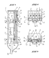
- a box 1 which will advantageously be mounted vertically in its support comprises a bottom part 2 and a cover part 3, which delimit an internal space isolated from the outside, which is intended to receive a first plate 4 serving as a support for the terminals 5 for connection of the power supply device to the electrical network and a second separate plate 6 supporting the lamp protection, supply and lighting equipment, called plate and shown schematically at 7.
- the plate 7 is electrically connected to the terminals 5 of the plate 4 by flexible cables 8.
- the housing 1 further comprises a hook 9 secured to the bottom 2 and intended for the attachment of the housing 1 inside the candelabrum of which only the support strip 10 is shown diagrammatically.
- the plate 4 is slidably mounted in lateral grooves 11 and 12 of the bottom 2 which is advantageously of elongated shape and for example produced by extrusion.
- This arrangement allows easy positioning in terminals 5 of the electric power supply cables 13 generally having a large cross section and great rigidity.
- the installation of the cables in the terminals 5 is facilitated by the possibility of adjusting the height of the said terminals.
- the plate 4 can be locked in its appropriate position using a locking screw 14.
- the terminals 5 can also serve as a relay between a candelabra and the following candelabra or candelabras and can therefore support several power cables for candelabras located upstream and downstream.
- the support plate 6 is removably mounted on the bottom 2 to facilitate repair work in the event of a defect in the lamp supply equipment.
- the support 6 and the bottom 2 are shaped in such a way that the disassembly of this support and of the plate 7 is easy and can be carried out without disturbing the continuity of the supply of electricity to the entire installation.
- the plate 6 has a width less than the distance between the inner edges 15 and 16 of the grooves 11 and 12 of the bottom 2. Its attachment to the bottom 2 is advantageously carried out by means of two hooks 17, 18 having bases. enlarged respectively 19 and 20 which are capable of sliding inside grooves 21 and 22 of the bottom 2. The hooks can be locked using locking screws 23, 24.
- the plate 6 can be easily mounted in the housing 1, when the cover 3 is removed, by positioning the orifices 25, 26 of the plate 6 on the respective hooks 17, 18 placed at the correct height.
- the dismantling of the plate 6 does not affect the connections of the cables 13 to the terminals 5. It should be noted that the plates 4 and 6 are advantageously flat.
- the hook 9 can comprise a part 30 capable of sliding inside a groove 31 of the bottom 2 and include a locking screw 32.
- This hook is used to hang the housing 1 on the inside the candelabrum on the hanging bar 10 provided for this purpose and be able to adjust the height.
- end 36 of the housing which is open to facilitate the positioning of the supply cables 13, can advantageously be closed by means of an elastic sleeve 37, the part of which d end 38 is supported on the external surface 39 of the end of the housing 1, while the opposite end portion 40 allows the insertion of electrical cables 13.
- This arrangement is advantageous because it provides the housing 1 with effective protection of the parts active under voltage located inside the housing.
Landscapes
- Engineering & Computer Science (AREA)
- General Engineering & Computer Science (AREA)
- Arrangement Of Elements, Cooling, Sealing, Or The Like Of Lighting Devices (AREA)
- Non-Portable Lighting Devices Or Systems Thereof (AREA)
- Fastening Of Light Sources Or Lamp Holders (AREA)
Priority Applications (1)
| Application Number | Priority Date | Filing Date | Title |
|---|---|---|---|
| DE88402618T DE3886540D1 (de) | 1988-10-17 | 1988-10-17 | Gehäuse für die Montage in einem Träger für eine elektrische Vorrichtung, insbesondere in einem Leuchtenträger oder einem hohlen Mast. |
Applications Claiming Priority (1)
| Application Number | Priority Date | Filing Date | Title |
|---|---|---|---|
| FR8705850A FR2614495B1 (fr) | 1987-04-24 | 1987-04-24 | Boitier montable dans un support d'un dispositif electrique notamment un support de candelabre tel qu'un candelabre d'eclairage public ou un poteau creux |
Publications (2)
| Publication Number | Publication Date |
|---|---|
| EP0364643A1 true EP0364643A1 (de) | 1990-04-25 |
| EP0364643B1 EP0364643B1 (de) | 1993-12-22 |
Family
ID=9350462
Family Applications (1)
| Application Number | Title | Priority Date | Filing Date |
|---|---|---|---|
| EP88402618A Expired - Lifetime EP0364643B1 (de) | 1987-04-24 | 1988-10-17 | Gehäuse für die Montage in einem Träger für eine elektrische Vorrichtung, insbesondere in einem Leuchtenträger oder einem hohlen Mast |
Country Status (2)
| Country | Link |
|---|---|
| EP (1) | EP0364643B1 (de) |
| FR (1) | FR2614495B1 (de) |
Cited By (5)
| Publication number | Priority date | Publication date | Assignee | Title |
|---|---|---|---|---|
| EP0497061A1 (de) * | 1989-07-21 | 1992-08-05 | Bruno Paul Claude Marcoz | Isolierter Anschlusskasten, insbesondere für Montage in Lichtmasten |
| FR2685133A1 (fr) * | 1991-12-17 | 1993-06-18 | Mussi Michel | Moyens de raccordement electrique protege pour l'alimentation de luminaires publics ou autres appareils. |
| EP0740106A1 (de) * | 1995-04-24 | 1996-10-30 | PAUL JORDAN ELEKTROTECHNISCHE FABRIK, GmbH & Co. | Anschlusskasten mit rastbaren Einbauteilen |
| FR2815777A1 (fr) * | 2000-10-25 | 2002-04-26 | Depagne | Dispositif de protection d'un connecteur de cable electrique installe d'un poteau |
| FR2877778A1 (fr) * | 2004-11-10 | 2006-05-12 | Bruno Paul Claude Marcoz | Dispositif d'isolation et d'emboitage des appareillages de connexion electrique d'un recepteur supporte par un poteau creux tel un candelabre, a un reseau d'approvisionnement en energie, notamment un reseau d'eclairage public |
Families Citing this family (5)
| Publication number | Priority date | Publication date | Assignee | Title |
|---|---|---|---|---|
| FR2690599B1 (fr) * | 1992-04-27 | 1994-07-29 | Sogexi Sa | Boitier isolant de connexion electrique, montable notamment dans un poteau evide tel qu'un support de lampadaire. |
| FR2690600B1 (fr) * | 1992-04-28 | 1994-08-12 | Sogexi Sa | Boîtier isolant de connexion électrique, montable notamment dans un poteau tel qu'un support de lampadaire. |
| FR2753012B1 (fr) * | 1996-09-02 | 1998-11-06 | Stratinor | Agencement d'une platine support d'appareillage dans un coffret notamment de gaz, d'electricite ou d'eau |
| FR2973175B1 (fr) * | 2011-03-24 | 2014-02-07 | Gen Exp Ind | Boitier de connexion electrique pour l'eclairage public ou la signalisation routiere |
| FR3076666B1 (fr) * | 2018-01-08 | 2019-12-13 | Ludovic Lefebvre | Coffret electrique pour poteau d'eclairage, ensemble et procede de montage correspondant |
Citations (3)
| Publication number | Priority date | Publication date | Assignee | Title |
|---|---|---|---|---|
| BE717044A (de) * | 1967-06-28 | 1968-12-02 | ||
| FR2057188A5 (de) * | 1969-08-05 | 1971-05-21 | Fronty Jean | |
| FR2602116A1 (fr) * | 1986-07-24 | 1988-01-29 | Sogexi General Export Ind Sa | Boitier de protection, principalement destine a recevoir les connexions et les appareillages d'alimentation des lampes d'eclairage public |
-
1987
- 1987-04-24 FR FR8705850A patent/FR2614495B1/fr not_active Expired - Lifetime
-
1988
- 1988-10-17 EP EP88402618A patent/EP0364643B1/de not_active Expired - Lifetime
Patent Citations (3)
| Publication number | Priority date | Publication date | Assignee | Title |
|---|---|---|---|---|
| BE717044A (de) * | 1967-06-28 | 1968-12-02 | ||
| FR2057188A5 (de) * | 1969-08-05 | 1971-05-21 | Fronty Jean | |
| FR2602116A1 (fr) * | 1986-07-24 | 1988-01-29 | Sogexi General Export Ind Sa | Boitier de protection, principalement destine a recevoir les connexions et les appareillages d'alimentation des lampes d'eclairage public |
Cited By (5)
| Publication number | Priority date | Publication date | Assignee | Title |
|---|---|---|---|---|
| EP0497061A1 (de) * | 1989-07-21 | 1992-08-05 | Bruno Paul Claude Marcoz | Isolierter Anschlusskasten, insbesondere für Montage in Lichtmasten |
| FR2685133A1 (fr) * | 1991-12-17 | 1993-06-18 | Mussi Michel | Moyens de raccordement electrique protege pour l'alimentation de luminaires publics ou autres appareils. |
| EP0740106A1 (de) * | 1995-04-24 | 1996-10-30 | PAUL JORDAN ELEKTROTECHNISCHE FABRIK, GmbH & Co. | Anschlusskasten mit rastbaren Einbauteilen |
| FR2815777A1 (fr) * | 2000-10-25 | 2002-04-26 | Depagne | Dispositif de protection d'un connecteur de cable electrique installe d'un poteau |
| FR2877778A1 (fr) * | 2004-11-10 | 2006-05-12 | Bruno Paul Claude Marcoz | Dispositif d'isolation et d'emboitage des appareillages de connexion electrique d'un recepteur supporte par un poteau creux tel un candelabre, a un reseau d'approvisionnement en energie, notamment un reseau d'eclairage public |
Also Published As
| Publication number | Publication date |
|---|---|
| FR2614495B1 (fr) | 1990-12-21 |
| FR2614495A1 (fr) | 1988-10-28 |
| EP0364643B1 (de) | 1993-12-22 |
Similar Documents
| Publication | Publication Date | Title |
|---|---|---|
| EP0364643B1 (de) | Gehäuse für die Montage in einem Träger für eine elektrische Vorrichtung, insbesondere in einem Leuchtenträger oder einem hohlen Mast | |
| FR2633369A1 (fr) | Perfectionnement aux systemes de fixation en connexion rapide pour des lampes, en particulier des lampes ayant un boitier resistant aux intemperies | |
| FR2585450A1 (fr) | Dispositif d'eclairage d'ambiance | |
| WO1993000552A1 (fr) | Dispositif de montage reglable d'un spot | |
| EP0551041B1 (de) | Beleuchtungs- und Hängevorrichtung in Einzelausführung und in modularer Bauweise zum Aufhängen von Objekten | |
| FR2731885A1 (fr) | Installation d'etageres demontables | |
| FR2568984A1 (fr) | Cimaise de securite auto-eclairante | |
| CH629341A5 (fr) | Douille de lampe articulee. | |
| FR2769404A1 (fr) | Boitier pour un appareil electrique tel un disjoncteur | |
| FR2658588A1 (fr) | Bloc d'eclairage etanche. | |
| BE1005448A6 (fr) | Appareil d'eclairage. | |
| FR2721093A1 (fr) | Luminaire, notamment pour l'éclairage public ou industriel, comportant un corps de réflecteur et un dispositif porte-douille de source lumineuse amovible par rapport à ce premier. | |
| FR2982928A1 (fr) | Dispositif d'eclairage d'une zone subjacente | |
| FR2731332A1 (fr) | Dispositif d'affichage perfectionne | |
| FR2764363A1 (fr) | Lanterne pour l'eclairage en exterieur | |
| CH617256A5 (en) | Lamp | |
| FR2685060A1 (fr) | Lampe torche modulaire. | |
| CH442469A (fr) | Canalisation de support pour appareils électriques | |
| EP0676585B1 (de) | Leuchte für eine Leuchtstoffröhre | |
| EP0541428A1 (de) | Niedervolt-Leuchte mit Trägerschiene | |
| FR2759478A1 (fr) | Dispositif destine a eclairer une surface translucide et enseigne lumineuse mettant en oeuvre ce dispositif | |
| FR2702032A1 (fr) | Dispositif de fixation d'un luminaire sur une boîte de connexion et luminaire muni de ce dispositif. | |
| FR2834546A1 (fr) | Applique d'eclairage comprenant un dispositif de fixation de douille de lampe | |
| EP0344127B1 (de) | Halogenlampenfassungsträger und Fixiergerät für die entsprechenden Stromzuführungen | |
| EP0028553A1 (de) | Niederspannungsverteilerkasten mit Erhöhungssockel |
Legal Events
| Date | Code | Title | Description |
|---|---|---|---|
| PUAI | Public reference made under article 153(3) epc to a published international application that has entered the european phase |
Free format text: ORIGINAL CODE: 0009012 |
|
| AK | Designated contracting states |
Kind code of ref document: A1 Designated state(s): BE CH DE GB IT LI |
|
| 17P | Request for examination filed |
Effective date: 19901016 |
|
| 17Q | First examination report despatched |
Effective date: 19930303 |
|
| GRAA | (expected) grant |
Free format text: ORIGINAL CODE: 0009210 |
|
| AK | Designated contracting states |
Kind code of ref document: B1 Designated state(s): BE CH DE GB IT LI |
|
| PG25 | Lapsed in a contracting state [announced via postgrant information from national office to epo] |
Ref country code: IT Free format text: LAPSE BECAUSE OF FAILURE TO SUBMIT A TRANSLATION OF THE DESCRIPTION OR TO PAY THE FEE WITHIN THE PRE;WARNING: LAPSES OF ITALIAN PATENTS WITH EFFECTIVE DATE BEFORE 2007 MAY HAVE OCCURRED AT ANY TIME BEFORE 2007. THE CORRECT EFFECTIVE DATE MAY BE DIFFERENT FROM THE ONE RECORDED.SCRIBED TIME-LIMIT Effective date: 19931222 Ref country code: DE Effective date: 19931222 Ref country code: GB Effective date: 19931222 |
|
| REF | Corresponds to: |
Ref document number: 3886540 Country of ref document: DE Date of ref document: 19940203 |
|
| GBV | Gb: ep patent (uk) treated as always having been void in accordance with gb section 77(7)/1977 [no translation filed] |
Effective date: 19931222 |
|
| PLBE | No opposition filed within time limit |
Free format text: ORIGINAL CODE: 0009261 |
|
| STAA | Information on the status of an ep patent application or granted ep patent |
Free format text: STATUS: NO OPPOSITION FILED WITHIN TIME LIMIT |
|
| PG25 | Lapsed in a contracting state [announced via postgrant information from national office to epo] |
Ref country code: CH Effective date: 19941031 Ref country code: LI Effective date: 19941031 |
|
| 26N | No opposition filed | ||
| REG | Reference to a national code |
Ref country code: CH Ref legal event code: PL |
|
| PGFP | Annual fee paid to national office [announced via postgrant information from national office to epo] |
Ref country code: BE Payment date: 19961212 Year of fee payment: 9 |
|
| PG25 | Lapsed in a contracting state [announced via postgrant information from national office to epo] |
Ref country code: BE Free format text: LAPSE BECAUSE OF NON-PAYMENT OF DUE FEES Effective date: 19971031 |
|
| BERE | Be: lapsed |
Owner name: MARCOZ BRUNO PAUL CLAUDE Effective date: 19971031 |