EP0364649B1 - Dispositif de chauffage pour siège de vehicule - Google Patents
Dispositif de chauffage pour siège de vehicule Download PDFInfo
- Publication number
- EP0364649B1 EP0364649B1 EP88850293A EP88850293A EP0364649B1 EP 0364649 B1 EP0364649 B1 EP 0364649B1 EP 88850293 A EP88850293 A EP 88850293A EP 88850293 A EP88850293 A EP 88850293A EP 0364649 B1 EP0364649 B1 EP 0364649B1
- Authority
- EP
- European Patent Office
- Prior art keywords
- vehicle seat
- temperature
- temperature level
- heating
- control
- Prior art date
- Legal status (The legal status is an assumption and is not a legal conclusion. Google has not performed a legal analysis and makes no representation as to the accuracy of the status listed.)
- Expired - Lifetime
Links
- 238000010438 heat treatment Methods 0.000 title claims description 35
- 238000010276 construction Methods 0.000 title claims description 16
- 230000009849 deactivation Effects 0.000 claims description 11
- 230000004913 activation Effects 0.000 claims description 10
- 238000005485 electric heating Methods 0.000 claims description 4
- 239000003990 capacitor Substances 0.000 claims description 2
- 230000003213 activating effect Effects 0.000 claims 2
- 230000002093 peripheral effect Effects 0.000 claims 1
- 239000004744 fabric Substances 0.000 description 3
- 239000002131 composite material Substances 0.000 description 2
- 230000001276 controlling effect Effects 0.000 description 2
- 238000010586 diagram Methods 0.000 description 2
- 230000000694 effects Effects 0.000 description 2
- 230000006870 function Effects 0.000 description 2
- 238000004519 manufacturing process Methods 0.000 description 2
- 230000001105 regulatory effect Effects 0.000 description 2
- 239000004721 Polyphenylene oxide Substances 0.000 description 1
- 239000000853 adhesive Substances 0.000 description 1
- 230000001070 adhesive effect Effects 0.000 description 1
- 230000008901 benefit Effects 0.000 description 1
- 230000008859 change Effects 0.000 description 1
- 239000004020 conductor Substances 0.000 description 1
- 239000002360 explosive Substances 0.000 description 1
- 230000002349 favourable effect Effects 0.000 description 1
- 239000006260 foam Substances 0.000 description 1
- 230000036541 health Effects 0.000 description 1
- 230000000977 initiatory effect Effects 0.000 description 1
- 239000000463 material Substances 0.000 description 1
- 239000002184 metal Substances 0.000 description 1
- 238000000034 method Methods 0.000 description 1
- 239000004033 plastic Substances 0.000 description 1
- 229920000570 polyether Polymers 0.000 description 1
- 230000008569 process Effects 0.000 description 1
Images

Classifications
-
- B—PERFORMING OPERATIONS; TRANSPORTING
- B60—VEHICLES IN GENERAL
- B60N—SEATS SPECIALLY ADAPTED FOR VEHICLES; VEHICLE PASSENGER ACCOMMODATION NOT OTHERWISE PROVIDED FOR
- B60N2/00—Seats specially adapted for vehicles; Arrangement or mounting of seats in vehicles
- B60N2/56—Heating or ventilating devices
- B60N2/5678—Heating or ventilating devices characterised by electrical systems
- B60N2/5685—Resistance
Definitions
- the present invention relates to a vehicle-seat heating construction of the kind set forth in the preamble of Claim 1.
- the thermostat circuit with two temperature regulators which work in parallel so to say, and each of which is set to a respective temperature value.
- One of the thermostat circuits has a higher deactivation or switch-off temperature than the other, but operates only once, so that the vehicle seat temperature will first rise to the high temperature level, before the current is switched off. The temperature will then decrease and when it falls beneath the other set temperature level the current will again be switched on, whereafter the current is repeatedly switched off and on, in a conventional manner, so as to control the temperature to the lower of the two preset temperature levels.
- the higher starting temperature may also be reached with the aid of a time circuit, wherein during the starting process full power is permitted to prevail for a predetermined time period or for a time period which is determined by the temperature of the vehicle seat at the time of starting the heating process, and the temperature is subsequently controlled at a comfortable level when this time period has lapsed.
- the first circuit may be constructed so as to be activated at 19°C and deactivated at 39°C, whereas the other circuit is constructed for activation at 27°C and deactivation at 31°C.
- the first mentioned circuit which is effective in heating the vehicle seat initially, will only begin to generate heat when the temperature of the sitting-part of the vehicle seat is beneath 19°C, which means that the temporary absence of the driver from his seat will not result in the initiation of a new starting sequence as soon as he reseats himself.
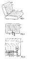
- control devices 6 are located at the one edge 5 of the heating plate 4, such as to be protected by the lower edge part of the back-rest 11, as shown in Figure 1 and Figure 2.
- FIG 4 illustrates the construction of the electric circuit.
- the electric heating element 1 illustrated in Figure 4 may also include the electric heating element 20 of the back-rest, shown in Figure 1, and may be connected either in series or in parallel (not shown).
- the positive and negative terminals of the circuit are connected to the electric current supply source of the vehicle via electric switches not snown, e.g. a manually operated switch having connected in series therewith a switch which is operated by the load on the vehicle seat concerned.
- the electrolytic capacitor 40 of 1 uF which is connected between earth and the voltage dividing point for the positive input of the comparator 41.
- the positive input will initially have a lower voltage than the negative input connected to the sensor, so that the comparator will not then become active.
- a prerequisite in this respect is namely that the sensor voltage is lower than the voltage on the positive input.
Landscapes
- Engineering & Computer Science (AREA)
- Aviation & Aerospace Engineering (AREA)
- Transportation (AREA)
- Mechanical Engineering (AREA)
- Chair Legs, Seat Parts, And Backrests (AREA)
- Control Of Resistance Heating (AREA)
- Seats For Vehicles (AREA)
Claims (7)
Priority Applications (2)
| Application Number | Priority Date | Filing Date | Title |
|---|---|---|---|
| DE8888850293T DE3866702D1 (de) | 1988-09-06 | 1988-09-06 | Anordnung der sitzheizung eines fahrzeugs. |
| EP88850293A EP0364649B1 (fr) | 1988-09-06 | 1988-09-06 | Dispositif de chauffage pour siège de vehicule |
Applications Claiming Priority (1)
| Application Number | Priority Date | Filing Date | Title |
|---|---|---|---|
| EP88850293A EP0364649B1 (fr) | 1988-09-06 | 1988-09-06 | Dispositif de chauffage pour siège de vehicule |
Publications (2)
| Publication Number | Publication Date |
|---|---|
| EP0364649A1 EP0364649A1 (fr) | 1990-04-25 |
| EP0364649B1 true EP0364649B1 (fr) | 1991-12-04 |
Family
ID=8200669
Family Applications (1)
| Application Number | Title | Priority Date | Filing Date |
|---|---|---|---|
| EP88850293A Expired - Lifetime EP0364649B1 (fr) | 1988-09-06 | 1988-09-06 | Dispositif de chauffage pour siège de vehicule |
Country Status (2)
| Country | Link |
|---|---|
| EP (1) | EP0364649B1 (fr) |
| DE (1) | DE3866702D1 (fr) |
Families Citing this family (3)
| Publication number | Priority date | Publication date | Assignee | Title |
|---|---|---|---|---|
| DE19601969A1 (de) * | 1996-01-20 | 1997-07-24 | Daimler Benz Ag | Elektrisch kontaktierbare Funktionsmatte, insbesondere Sensormatte oder Heizmatte |
| US7477969B2 (en) | 2003-10-02 | 2009-01-13 | W.E.T. Automotive Systems Ag | Temperature conditioned assembly having a controller in communication with a temperature sensor |
| US9290118B2 (en) | 2013-10-08 | 2016-03-22 | The Boeing Company | Heated flight attendant jumpseats for commercial airplane applications |
Family Cites Families (1)
| Publication number | Priority date | Publication date | Assignee | Title |
|---|---|---|---|---|
| DE7913491U1 (de) * | 1979-05-10 | 1979-11-08 | Stegt, Christian, Dipl.-Ing. | Nachruestbare autositzbeheizung |
-
1988
- 1988-09-06 EP EP88850293A patent/EP0364649B1/fr not_active Expired - Lifetime
- 1988-09-06 DE DE8888850293T patent/DE3866702D1/de not_active Expired - Lifetime
Also Published As
| Publication number | Publication date |
|---|---|
| EP0364649A1 (fr) | 1990-04-25 |
| DE3866702D1 (de) | 1992-01-16 |
Similar Documents
| Publication | Publication Date | Title |
|---|---|---|
| US10076982B2 (en) | Occupancy sensing with heating devices | |
| JP2004504082A (ja) | 車両シートの加熱構成 | |
| EP0126162B1 (fr) | Corps de chauffe pour le siege d'un vehicule | |
| US7823967B2 (en) | Heater system for an aircraft seat | |
| US20040011778A1 (en) | Device and method for heating of a seat | |
| US9045066B2 (en) | Heater control unit and vehicle seat heater | |
| US20140152057A1 (en) | Heated headrest | |
| US20150232006A1 (en) | Heating apparatus for automobile seat and control method thereof | |
| WO1984004440A1 (fr) | Coussin thermo-electrique pour sieges et dossiers | |
| JPH07508233A (ja) | 車両シート | |
| US20200391634A1 (en) | Vehicle seat heater and vehicle seat | |
| GB2200806A (en) | Method and device for adjusting the heat flow in heated seats | |
| US20050085968A1 (en) | Temperature conditioned assembly having a controller in communication with a temperature sensor | |
| JP6361499B2 (ja) | 冷暖房装置システム | |
| JP6221985B2 (ja) | 輻射ヒータ装置 | |
| EP0364649A1 (fr) | Dispositif de chauffage pour siège de vehicule | |
| JP4902283B2 (ja) | シートヒータ | |
| JP7746902B2 (ja) | 車両用暖房装置 | |
| JPS58116216A (ja) | 車輛用補助暖房装置 | |
| JP6578893B2 (ja) | ヒータ装置 | |
| JPH0676920A (ja) | シート用ヒータ制御方法およびヒータ制御装置 | |
| EP1317699B1 (fr) | Dispositif et procede de chauffage d'un siege | |
| JPH06342686A (ja) | 電気発熱装置 | |
| JPH06301427A (ja) | シートヒータの制御装置 | |
| JPH07237511A (ja) | 自動車付属機器の制御装置 |
Legal Events
| Date | Code | Title | Description |
|---|---|---|---|
| PUAI | Public reference made under article 153(3) epc to a published international application that has entered the european phase |
Free format text: ORIGINAL CODE: 0009012 |
|
| AK | Designated contracting states |
Kind code of ref document: A1 Designated state(s): BE DE FR GB NL SE |
|
| 17P | Request for examination filed |
Effective date: 19901023 |
|
| 17Q | First examination report despatched |
Effective date: 19910201 |
|
| RAP1 | Party data changed (applicant data changed or rights of an application transferred) |
Owner name: SCANDMEC AB |
|
| GRAA | (expected) grant |
Free format text: ORIGINAL CODE: 0009210 |
|
| AK | Designated contracting states |
Kind code of ref document: B1 Designated state(s): BE DE FR GB NL SE |
|
| PG25 | Lapsed in a contracting state [announced via postgrant information from national office to epo] |
Ref country code: SE Effective date: 19911204 Ref country code: NL Effective date: 19911204 Ref country code: FR Effective date: 19911204 Ref country code: BE Effective date: 19911204 |
|
| REF | Corresponds to: |
Ref document number: 3866702 Country of ref document: DE Date of ref document: 19920116 |
|
| EN | Fr: translation not filed | ||
| NLV1 | Nl: lapsed or annulled due to failure to fulfill the requirements of art. 29p and 29m of the patents act | ||
| PLBE | No opposition filed within time limit |
Free format text: ORIGINAL CODE: 0009261 |
|
| STAA | Information on the status of an ep patent application or granted ep patent |
Free format text: STATUS: NO OPPOSITION FILED WITHIN TIME LIMIT |
|
| 26N | No opposition filed | ||
| REG | Reference to a national code |
Ref country code: GB Ref legal event code: IF02 |
|
| PGFP | Annual fee paid to national office [announced via postgrant information from national office to epo] |
Ref country code: GB Payment date: 20030828 Year of fee payment: 16 |
|
| PGFP | Annual fee paid to national office [announced via postgrant information from national office to epo] |
Ref country code: DE Payment date: 20030925 Year of fee payment: 16 |
|
| PG25 | Lapsed in a contracting state [announced via postgrant information from national office to epo] |
Ref country code: GB Free format text: LAPSE BECAUSE OF NON-PAYMENT OF DUE FEES Effective date: 20040906 |
|
| PG25 | Lapsed in a contracting state [announced via postgrant information from national office to epo] |
Ref country code: DE Free format text: LAPSE BECAUSE OF NON-PAYMENT OF DUE FEES Effective date: 20050401 |
|
| GBPC | Gb: european patent ceased through non-payment of renewal fee |
Effective date: 20040906 |