EP0364751A1 - Méthode et dispositif pour contrôler la position du point de traction d'un tracteur avec charrue - Google Patents
Méthode et dispositif pour contrôler la position du point de traction d'un tracteur avec charrue Download PDFInfo
- Publication number
- EP0364751A1 EP0364751A1 EP89117364A EP89117364A EP0364751A1 EP 0364751 A1 EP0364751 A1 EP 0364751A1 EP 89117364 A EP89117364 A EP 89117364A EP 89117364 A EP89117364 A EP 89117364A EP 0364751 A1 EP0364751 A1 EP 0364751A1
- Authority
- EP
- European Patent Office
- Prior art keywords
- plow
- sensor
- plow body
- tractor
- contact force
- Prior art date
- Legal status (The legal status is an assumption and is not a legal conclusion. Google has not performed a legal analysis and makes no representation as to the accuracy of the status listed.)
- Granted
Links
- 238000000034 method Methods 0.000 title claims abstract description 21
- 238000005259 measurement Methods 0.000 claims abstract description 5
- 210000000481 breast Anatomy 0.000 claims description 4
- 230000001105 regulatory effect Effects 0.000 claims description 2
- 230000001276 controlling effect Effects 0.000 claims 1
- 238000005452 bending Methods 0.000 abstract description 5
- 239000002689 soil Substances 0.000 description 6
- 230000008859 change Effects 0.000 description 5
- 230000002349 favourable effect Effects 0.000 description 4
- 230000008569 process Effects 0.000 description 4
- 238000013461 design Methods 0.000 description 3
- 230000004048 modification Effects 0.000 description 3
- 238000012986 modification Methods 0.000 description 3
- 230000008901 benefit Effects 0.000 description 2
- 239000002131 composite material Substances 0.000 description 2
- 230000007257 malfunction Effects 0.000 description 2
- 238000012937 correction Methods 0.000 description 1
- 230000006866 deterioration Effects 0.000 description 1
- 238000010586 diagram Methods 0.000 description 1
- 230000008439 repair process Effects 0.000 description 1
Images

Classifications
-
- A—HUMAN NECESSITIES
- A01—AGRICULTURE; FORESTRY; ANIMAL HUSBANDRY; HUNTING; TRAPPING; FISHING
- A01B—SOIL WORKING IN AGRICULTURE OR FORESTRY; PARTS, DETAILS, OR ACCESSORIES OF AGRICULTURAL MACHINES OR IMPLEMENTS, IN GENERAL
- A01B15/00—Elements, tools, or details of ploughs
- A01B15/14—Frames
Definitions
- the invention relates to a method and a device for regulating the position of the pull point of a combination comprising a tractor and a plow.
- the control device will, however, endeavor to compensate for the lateral component of the ground forces occurring due to the hanging position, ie to shift the pulling point further up the slope. Taking into account the directions of the handlebar forces or the position of the pulling point and the pulling line of the team, it follows that the force which occurs on the handlebar above the slope is greater than the force of the lower link arranged below the slope. The balance of forces in the handlebars changes, although the point of application of force on the plow bodies has not changed. This inevitably leads to an undesirable malfunction of the control device.
- DE-OS 28 45 111, DE-AS 11 68 148 and DE-OS 32 48 633 each show devices for adjusting the cutting width and the position of the traction point. These devices allow appropriate adjustment by manual operation.
- the invention has for its object to provide a device and a method of the type mentioned which, with a simple structure and high operational reliability, enable the plow to be reduced or minimized and energy cost-saving adjustment of the plow and ensure working with the most favorable traction .
- the object is achieved with respect to the device in that the contact force of a plow body on the furrow wall is determined by means of at least one sensor and a control device is supplied to adjust the position of the pulling point of the plow.
- the device according to the invention is distinguished by a number of considerable advantages. Since, according to the invention, it is not forces in the handlebars, but rather the contact force of the plow body on the furrow wall that is measured, it is possible to rule out other force influences which can lead to a falsification of the recorded measured value and to incorrect regulation. It is therefore according to the invention possible to preselect the contact force in such a way that a proper guidance of the plow body, preferably the rear plow body of a plow, which is provided with several plow bodies, and thus the entire plow on the furrow wall is ensured.
- the senor is arranged in the region of the rear plow body mounted on a plow frame. This ensures that exact regulation is possible even with such a plow.
- the difference in the forces acting on the lower links in a plow which is designed in accordance with the aforementioned patent 33 45 231 is not so great that an exact regulation which takes account of different arable conditions is possible.
- the senor is in the form of a pressure sensor which is arranged in the area between a system and a plow body breast.
- This embodiment has proven to be particularly favorable, since fastening points, for example screws or bolt connections, which are already structurally present are usually provided, in the area of which a pressure sensor, for example in the form of a piezo pressure transducer, can be arranged. Furthermore, it is with this type of
- Design and arrangement of a sensor is particularly easy to carry out an adjustment of the sensor or a calibration, since only suitable fastening elements have to be tightened or loosened. However, it is also possible to carry out the calibration using an electronic control device.
- the senor in the form of a strain sensor on a system of the plow body, taking into account that the system of the plow body is caused by the tilting and bending moments that occur as a function of the contact force acting on the plow body acts, is deformed.
- the sensor on the plow of a plow body and also to design it in the form of a strain gauge consisting of strain gauges.
- This embodiment also takes advantage of the fact that the spindle deforms as a function of the contact force on the plow body, so that a direct determination of the force acting on the plow body itself is possible in this way.
- the sensor can also prove to be advantageous to arrange the sensor on the connection region of a multi-part spindle of a plow body.
- the shaft can be assembled, for example, by screwing several parts together, so that it is possible to arrange the sensor in the screwing area, ie in the area of the pin or bolt. It may be possible to determine the deformation of the spindle as well as the torsion or deformation of a pin.
- the spindle i.e. to form with an articulated area and to arrange the sensor on this articulated area.
- the joint can be held in a specific pretension position by means of a spring, wherein the spring or the spring element can be connected to the sensor.
- a further advantageous embodiment of the device according to the invention is provided in that the sensor is arranged in the fastening area of a plow of a plow body on a contact surface.
- the shaft is screwed to a bracket, with either the shaft or the bracket being subjected to bending when the plow body is subjected to a force.
- fastening elements which are used to fasten the shaft to the bracket, in order to determine the contact force of the plow body in this way.
- the sensors it is thus possible to arrange the sensors in the wider area of the respective ploughshare or the plow body; it is not always necessary to determine the contact force in direct association with the plow body. According to the invention, there is thus the possibility of selecting particularly favorable attachment points for the sensors, which are insensitive, in particular, to the loads and damage occurring during plowing. Furthermore, it is possible according to the invention to replace or repair the plow bodies if necessary, without the measurement sensors being affected thereby.
- the contact force cannot, of course, be measured directly. rather, a force or tension can be measured, which depends on the lateral component of the resulting force, the forces acting on the plow body.
- the force differences measured in this way can be converted in a simple manner in the control device, so that the contact force itself is available as an output variable.
- the driver of the tractor can make the adjustment in a simple manner.
- This sensor can either be provided on the plow or on the tractor and is preferably connected to the control unit in such a way that it can make a corresponding adjustment to the setpoint of the system force without the operator having to manually intervene in the control process.
- the position of the pulling point is preferably adjusted by means of at least one variable-length handlebar connecting the plow frame with an attachment device.
- This type of setting is characterized by a high degree of mechanical robustness and is particularly susceptible to malfunctions, so that it is ensured that the traction point can be adjusted in a suitable manner.
- the cutting width is set by means of a link arranged on the tractor in the area of the plow's mounting. An adjustment of the position of the pull point by the control therefore does not lead to a change in the cutting width and can take place independently of this.
- the setting is preferably carried out by means of hydraulic cylinders, since these can be controlled and actuated in a particularly simple manner by means of electronic regulation.
- the position of the traction point is preferably set to a predetermined target value by means of the regulator tion device fully automatically, so that the operator does not have to carry out any further operations once the plow has been adapted to the tractor.
- the position of the pull point on the driver's cab of the tractor is displayed by means of a display device.
- the operator can then determine in which system force range the plow is operating in order to make corresponding changes manually, if necessary, for example by changing the steering angle of the front wheels of the tractor or the like or influencing the control device.
- the invention can be used in both bed plows and rotary plows.
- care must be taken to ensure that an effective rotary sensor is available for the control device for each working direction.
- the right and left plow bodies have their own sensors, which can be used optionally.
- a handlebar arrangement with two handlebars is advantageously selected, which are arranged so that their Cut extensions in or near the pull point. This avoids influencing the cutting width when changing the pole position.
- the invention is achieved in that the contact force measured in the area of a plow body is kept constant at a predetermined value by adjusting the position of the pulling point of the plow, which is adjustable in plan view. Changes in the soil structure or in the geometry of the terrain therefore do not lead to an increase in the contact force and to a deterioration in the efficiency of the tractor or to a higher energy expenditure.
- the contact force of the plow against a furrow is measured directly, but it is also possible to determine the contact force of a plow against a furrow from the side component of the forces occurring on the plow body. It is thus possible according to the invention either to measure the contact force directly on the rearmost plow body, or to determine the total forces occurring on the rearmost plow body or on a central plow body and / or to measure the contact force separately on a further plow body. From the force difference thus present, it is possible to directly determine the contact force. Furthermore, it is possible according to the invention to measure and compare tensions in the area of the spindle both in the rearmost plow body and in another plow body in order to make a corresponding change in the regulation.
- the determination of the contact force can also take place in such a way that a substantial change occurs in the plow body Forces are determined, which can occur, for example, if the plow maintains its position relative to the tractor and the pull point position is unchanged, but if for another reason, for example because it was driven from a level into a slope, or the ground has become heavier , or the working depth has changed, the tractive force increases. Not only the resistance forces of all plow bodies and the lower link forces increase in the same ratio, but also the contact force of the lateral component of the individual soil forces.
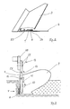
- the tractor 1 shown in top view in FIG. 1 has a chassis in the usual way, only the rear wheels 20 being shown to simplify the illustration.
- two lower links 18, 19 are articulated, on which a three-point tower 21 is mounted in the usual way.
- the upper link of the three-point tower 21 was not shown.
- the two lower links 18 and 19 are inclined at an angle to one another, in plan view, the ideal extensions of the lower links 18 and 19 end at a pull point 4.
- An attachment device 15 is attached to the three-point tower 21 and has a link 17 by means of which the cutting width of a plow 2 can be adjusted.
- the plow 2 comprises a plow frame 5 on which a plurality of plow bodies 3 are mounted.
- a support 22 is attached to the plow frame 5, which has two links 23, 24 and a length-adjustable link 16, with the aid of which it is possible to adjust the position of the plow frame 5.
- FIG. 2 shows a view of the rear plow body 3. This is connected to a system 6 via a plow body breast 7. As shown in FIG. 2, the plow body breast 7 can be connected to the system 6 via screw connections 25, 26.
- a pressure sensor 8 is arranged, which can be designed, for example, in the form of a piezo pressure sensor. It is therefore possible to measure the contact force which acts on the plow body 3 directly.
- FIG. 3 shows a rear view of the plow body shown in FIG. 2, different configurations of pressure sensors being shown in each case.
- the pressure sensor 8 shown in FIG. 2 is shown in FIG. 3, which is designed in the form of a piezo pressure sensor.
- the plow body is provided with a shaft 9, which can be provided with a joint or an articulated area 14 in its central region, and is connected to a holder 28 at its upper region via screw connections 27.
- a sensor 10 is arranged in a schematic manner, which can be designed in the form of a strain measuring sensor and detects deformations, i.e. Bending forces of the spindle are measured in order to determine the size of the contact force F.
- a sensor 11 can optionally be provided, which can be designed in the form of a spring and prestresses an articulated region of the spindle. This sensor can also be designed in the form of a pressure measuring or strain measuring sensor.
- the shaft is divided in the exemplary embodiments shown and connected by means of a profiled connecting bolt or connecting element 29, which can also be designed as a sensor and can be used to determine the force F by measuring the torsional forces.
- a further sensor 13 in the fastening areas of the spindle 9 with a holder 28, by means of which torsional or bending forces can be measured, from which the contact force F can be calculated.
- the exemplary embodiment shown in FIG. 3 has a large number of different sensors which are only shown together for the purpose of illustration. In the practical embodiment, only a single sensor is usually provided.
- FIG. 1 a top view of the rearmost plow body 3 shows a force diagram which shows the laterally acting force component of the contact force, the ground forces and the force component of the tensile force resulting therefrom. It can be seen from this illustration that it is possible in a simple manner to determine the total force in the area of one or more plow bodies in the manner described and to determine the plant force from this, which is to be used as the basis for the regulation according to the invention.
Landscapes
- Life Sciences & Earth Sciences (AREA)
- Engineering & Computer Science (AREA)
- Mechanical Engineering (AREA)
- Soil Sciences (AREA)
- Environmental Sciences (AREA)
- Lifting Devices For Agricultural Implements (AREA)
Applications Claiming Priority (2)
| Application Number | Priority Date | Filing Date | Title |
|---|---|---|---|
| DE3835812A DE3835812A1 (de) | 1988-10-21 | 1988-10-21 | Verfahren und vorrichtung zur regelung der lage des zugpunktes eines einen schlepper und einen pflug umfassenden gespanns |
| DE3835812 | 1988-10-21 |
Publications (2)
| Publication Number | Publication Date |
|---|---|
| EP0364751A1 true EP0364751A1 (fr) | 1990-04-25 |
| EP0364751B1 EP0364751B1 (fr) | 1994-04-20 |
Family
ID=6365579
Family Applications (1)
| Application Number | Title | Priority Date | Filing Date |
|---|---|---|---|
| EP89117364A Expired - Lifetime EP0364751B1 (fr) | 1988-10-21 | 1989-09-20 | Méthode et dispositif pour contrôler la position du point de traction d'un tracteur avec charrue |
Country Status (2)
| Country | Link |
|---|---|
| EP (1) | EP0364751B1 (fr) |
| DE (2) | DE3835812A1 (fr) |
Cited By (1)
| Publication number | Priority date | Publication date | Assignee | Title |
|---|---|---|---|---|
| FR2763206A1 (fr) * | 1997-05-15 | 1998-11-20 | Frederic Charlier | Charrue portee a nouveau dispositif de retournement |
Families Citing this family (2)
| Publication number | Priority date | Publication date | Assignee | Title |
|---|---|---|---|---|
| DE102017116592A1 (de) | 2017-07-24 | 2019-01-24 | Amazonen-Werke H. Dreyer Gmbh & Co. Kg | Verfahren zum Einstellen einer Zuglinie |
| DE102019205321A1 (de) * | 2019-04-12 | 2020-10-15 | Deere & Company | Verfahren zur Steuerung des Betriebs eines Anbaugerätes |
Citations (12)
| Publication number | Priority date | Publication date | Assignee | Title |
|---|---|---|---|---|
| DE1168148B (de) * | 1961-08-22 | 1964-04-16 | Rabewerk Clausing Heinrich | Anordnung zur Einstellung des Zugpunktes und der Arbeitsbreite bei Pfluegen |
| DE2845111A1 (de) * | 1978-10-17 | 1980-04-24 | Lemken Kg Pflugfab | Getriebe zur verstellung der breite und des ideellen schlepperzugpunktes eines pfluges |
| DE3248633A1 (de) * | 1982-12-30 | 1984-07-12 | Rabewerk Heinrich Clausing, 4515 Bad Essen | Pflug mit einer zugpunkt- und schnittbreiteneinstelleinrichtung |
| DE3345231C1 (de) * | 1983-12-14 | 1985-03-21 | Xaver Fendt & Co, 8952 Marktoberdorf | Regelverfahren und Vorrichtungen zum Betreiben eines aus einem Ackerschlepper und einem Pflug bestehenden Gespanns |
| DD221554A1 (de) * | 1984-02-02 | 1985-04-24 | Mech Landwirtsch Forschzent | Vorrichtung zur kontinuierlichen bodenfestigkeitsermittlung |
| DE3523775A1 (de) * | 1984-07-06 | 1986-01-16 | Vogel & Noot Landmaschinenfabrik GmbH, Wartberg | Vorrichtung zum selbstaendigen regeln eines an einem landwirtschaftlichen schlepper angebauten arbeitsgeraetes, insbesondere drehpfluges |
| GB2172486A (en) * | 1985-02-21 | 1986-09-24 | Ransomes Sims & Jefferies Plc | Reversible plough |
| EP0198405A2 (fr) * | 1985-04-12 | 1986-10-22 | Maschinenfabrik Bernard Krone GmbH | Charrue portée |
| AT381829B (de) * | 1985-05-30 | 1986-12-10 | Vogel & Noot Landmasch | Anbaupflug |
| DE3523748A1 (de) * | 1985-07-03 | 1987-01-29 | Eberhardt Pflugfabrik Gmbh | Anbaupflug mit steuerzugpunkteinstellung |
| DE3601465A1 (de) * | 1986-01-20 | 1987-07-30 | Eberhardt Pfluege Gmbh | Stein- und ueberlastsicherung fuer pfluege |
| DE3611414A1 (de) * | 1986-04-05 | 1987-10-08 | Helwig Dipl Ing Schmitt | Arbeitstiefenregelung an bodenbearbeitungsgeraeten |
-
1988
- 1988-10-21 DE DE3835812A patent/DE3835812A1/de not_active Withdrawn
-
1989
- 1989-09-20 EP EP89117364A patent/EP0364751B1/fr not_active Expired - Lifetime
- 1989-09-20 DE DE58907500T patent/DE58907500D1/de not_active Expired - Fee Related
Patent Citations (12)
| Publication number | Priority date | Publication date | Assignee | Title |
|---|---|---|---|---|
| DE1168148B (de) * | 1961-08-22 | 1964-04-16 | Rabewerk Clausing Heinrich | Anordnung zur Einstellung des Zugpunktes und der Arbeitsbreite bei Pfluegen |
| DE2845111A1 (de) * | 1978-10-17 | 1980-04-24 | Lemken Kg Pflugfab | Getriebe zur verstellung der breite und des ideellen schlepperzugpunktes eines pfluges |
| DE3248633A1 (de) * | 1982-12-30 | 1984-07-12 | Rabewerk Heinrich Clausing, 4515 Bad Essen | Pflug mit einer zugpunkt- und schnittbreiteneinstelleinrichtung |
| DE3345231C1 (de) * | 1983-12-14 | 1985-03-21 | Xaver Fendt & Co, 8952 Marktoberdorf | Regelverfahren und Vorrichtungen zum Betreiben eines aus einem Ackerschlepper und einem Pflug bestehenden Gespanns |
| DD221554A1 (de) * | 1984-02-02 | 1985-04-24 | Mech Landwirtsch Forschzent | Vorrichtung zur kontinuierlichen bodenfestigkeitsermittlung |
| DE3523775A1 (de) * | 1984-07-06 | 1986-01-16 | Vogel & Noot Landmaschinenfabrik GmbH, Wartberg | Vorrichtung zum selbstaendigen regeln eines an einem landwirtschaftlichen schlepper angebauten arbeitsgeraetes, insbesondere drehpfluges |
| GB2172486A (en) * | 1985-02-21 | 1986-09-24 | Ransomes Sims & Jefferies Plc | Reversible plough |
| EP0198405A2 (fr) * | 1985-04-12 | 1986-10-22 | Maschinenfabrik Bernard Krone GmbH | Charrue portée |
| AT381829B (de) * | 1985-05-30 | 1986-12-10 | Vogel & Noot Landmasch | Anbaupflug |
| DE3523748A1 (de) * | 1985-07-03 | 1987-01-29 | Eberhardt Pflugfabrik Gmbh | Anbaupflug mit steuerzugpunkteinstellung |
| DE3601465A1 (de) * | 1986-01-20 | 1987-07-30 | Eberhardt Pfluege Gmbh | Stein- und ueberlastsicherung fuer pfluege |
| DE3611414A1 (de) * | 1986-04-05 | 1987-10-08 | Helwig Dipl Ing Schmitt | Arbeitstiefenregelung an bodenbearbeitungsgeraeten |
Cited By (1)
| Publication number | Priority date | Publication date | Assignee | Title |
|---|---|---|---|---|
| FR2763206A1 (fr) * | 1997-05-15 | 1998-11-20 | Frederic Charlier | Charrue portee a nouveau dispositif de retournement |
Also Published As
| Publication number | Publication date |
|---|---|
| DE3835812A1 (de) | 1990-04-26 |
| DE58907500D1 (de) | 1994-05-26 |
| EP0364751B1 (fr) | 1994-04-20 |
Similar Documents
| Publication | Publication Date | Title |
|---|---|---|
| EP3278649B1 (fr) | Semoir et machine à semer comprenant plusieurs semoirs de ce type | |
| EP3026997B1 (fr) | Matériel de travail du sol muni d'un système de rappuyage | |
| EP1252806A2 (fr) | Interface entre véhicule de travail et outil ainsi que dispositif de contrôle | |
| DE2927585C2 (de) | Verfahren und Einrichtung zum Regeln der Arbeitstiefe eines von einer landwirtschaftlichen Zugmaschine, wie z.B. einem Schlepper getragenen Pfluges | |
| EP3903549B1 (fr) | Machine de traitement du sol, de préférence herse-étrille agricole et procédé de réglage d'une force de précontrainte sur une herse-étrille | |
| EP3772265B1 (fr) | Dispositif de houe | |
| DE102007048697A1 (de) | Hydraulische Hubeinrichtung | |
| DE102019122116A1 (de) | Landwirtschaftliches Gespann mit einer Zugmaschine und einem Pflug | |
| EP1018292B1 (fr) | Dispositif de levage pour bras inférieurs d'accouplement de tracteur | |
| WO2016192973A1 (fr) | Dispositif de commande pour un tracteur, tracteur présentant un dispositif de commande et procédé pour un dispositif de commande | |
| DE3331534C2 (fr) | ||
| EP2033503B1 (fr) | Charrue semi-portée | |
| EP3721691A1 (fr) | Procédé de commande du fonctionnement d'un accessoire | |
| DE19602893A1 (de) | Vorrichtung zur Regelung der Lage einer Bearbeitungseinheit einer landwirtschaftlichen Maschine | |
| EP0364751B1 (fr) | Méthode et dispositif pour contrôler la position du point de traction d'un tracteur avec charrue | |
| EP3782443A2 (fr) | Machine de traitement du sol agricole destinée au traitement des cultures sur rang | |
| DE19945853A1 (de) | Einrichtung zur Steuerung der Arbeitstiefe eines Bodenbearbeitungsgeräts, insbesondere eines Pfluges | |
| EP3300557B1 (fr) | Dispositif et procédé de controle du fonctionnement d'un appareil isolé hydraulique d'un véhicule | |
| EP1929852A1 (fr) | Dispositif destiné à déraciner ou à récolter de plantes à racines | |
| DE4222108A1 (de) | Zugkraftregelung | |
| DE3523748A1 (de) | Anbaupflug mit steuerzugpunkteinstellung | |
| DE2910180A1 (de) | Zugkraftregeleinrichtung | |
| DE19639573A1 (de) | Landwirtschaftliches Arbeitsfahrzeug, insbesondere Traktor | |
| DE10120733A1 (de) | Anbauvorrichtung zur Kopplung eines Arbeitsgerätes an ein Arbeitsfahrzeug | |
| DE3523775A1 (de) | Vorrichtung zum selbstaendigen regeln eines an einem landwirtschaftlichen schlepper angebauten arbeitsgeraetes, insbesondere drehpfluges |
Legal Events
| Date | Code | Title | Description |
|---|---|---|---|
| PUAI | Public reference made under article 153(3) epc to a published international application that has entered the european phase |
Free format text: ORIGINAL CODE: 0009012 |
|
| AK | Designated contracting states |
Kind code of ref document: A1 Designated state(s): DE FR GB |
|
| RAP1 | Party data changed (applicant data changed or rights of an application transferred) |
Owner name: RABEWERK GMBH + CO. |
|
| 17P | Request for examination filed |
Effective date: 19900426 |
|
| 17Q | First examination report despatched |
Effective date: 19910709 |
|
| GRAA | (expected) grant |
Free format text: ORIGINAL CODE: 0009210 |
|
| AK | Designated contracting states |
Kind code of ref document: B1 Designated state(s): DE FR GB |
|
| PG25 | Lapsed in a contracting state [announced via postgrant information from national office to epo] |
Ref country code: GB Effective date: 19940420 |
|
| REF | Corresponds to: |
Ref document number: 58907500 Country of ref document: DE Date of ref document: 19940526 |
|
| ET | Fr: translation filed | ||
| GBV | Gb: ep patent (uk) treated as always having been void in accordance with gb section 77(7)/1977 [no translation filed] |
Effective date: 19940420 |
|
| PLBE | No opposition filed within time limit |
Free format text: ORIGINAL CODE: 0009261 |
|
| STAA | Information on the status of an ep patent application or granted ep patent |
Free format text: STATUS: NO OPPOSITION FILED WITHIN TIME LIMIT |
|
| 26N | No opposition filed | ||
| PGFP | Annual fee paid to national office [announced via postgrant information from national office to epo] |
Ref country code: FR Payment date: 19980828 Year of fee payment: 10 |
|
| PGFP | Annual fee paid to national office [announced via postgrant information from national office to epo] |
Ref country code: DE Payment date: 19981028 Year of fee payment: 10 |
|
| PG25 | Lapsed in a contracting state [announced via postgrant information from national office to epo] |
Ref country code: FR Free format text: LAPSE BECAUSE OF NON-PAYMENT OF DUE FEES Effective date: 20000531 |
|
| PG25 | Lapsed in a contracting state [announced via postgrant information from national office to epo] |
Ref country code: DE Free format text: LAPSE BECAUSE OF NON-PAYMENT OF DUE FEES Effective date: 20000701 |
|
| REG | Reference to a national code |
Ref country code: FR Ref legal event code: ST |