EP0364781A2 - Serrure - Google Patents
Serrure Download PDFInfo
- Publication number
- EP0364781A2 EP0364781A2 EP89117975A EP89117975A EP0364781A2 EP 0364781 A2 EP0364781 A2 EP 0364781A2 EP 89117975 A EP89117975 A EP 89117975A EP 89117975 A EP89117975 A EP 89117975A EP 0364781 A2 EP0364781 A2 EP 0364781A2
- Authority
- EP
- European Patent Office
- Prior art keywords
- bolt
- profile cylinder
- locking
- latch
- lock
- Prior art date
- Legal status (The legal status is an assumption and is not a legal conclusion. Google has not performed a legal analysis and makes no representation as to the accuracy of the status listed.)
- Granted
Links
Images



Classifications
-
- E—FIXED CONSTRUCTIONS
- E05—LOCKS; KEYS; WINDOW OR DOOR FITTINGS; SAFES
- E05B—LOCKS; ACCESSORIES THEREFOR; HANDCUFFS
- E05B47/00—Operating or controlling locks or other fastening devices by electric or magnetic means
- E05B47/0001—Operating or controlling locks or other fastening devices by electric or magnetic means with electric actuators; Constructional features thereof
- E05B47/0012—Operating or controlling locks or other fastening devices by electric or magnetic means with electric actuators; Constructional features thereof with rotary electromotors
-
- E—FIXED CONSTRUCTIONS
- E05—LOCKS; KEYS; WINDOW OR DOOR FITTINGS; SAFES
- E05B—LOCKS; ACCESSORIES THEREFOR; HANDCUFFS
- E05B9/00—Lock casings or latch-mechanism casings ; Fastening locks or fasteners or parts thereof to the wing
- E05B9/08—Fastening locks or fasteners or parts thereof, e.g. the casings of latch-bolt locks or cylinder locks to the wing
- E05B9/084—Fastening of lock cylinders, plugs or cores
-
- E—FIXED CONSTRUCTIONS
- E05—LOCKS; KEYS; WINDOW OR DOOR FITTINGS; SAFES
- E05B—LOCKS; ACCESSORIES THEREFOR; HANDCUFFS
- E05B47/00—Operating or controlling locks or other fastening devices by electric or magnetic means
- E05B47/0001—Operating or controlling locks or other fastening devices by electric or magnetic means with electric actuators; Constructional features thereof
- E05B2047/0014—Constructional features of actuators or power transmissions therefor
- E05B2047/0018—Details of actuator transmissions
- E05B2047/002—Geared transmissions
-
- E—FIXED CONSTRUCTIONS
- E05—LOCKS; KEYS; WINDOW OR DOOR FITTINGS; SAFES
- E05B—LOCKS; ACCESSORIES THEREFOR; HANDCUFFS
- E05B47/00—Operating or controlling locks or other fastening devices by electric or magnetic means
- E05B47/0001—Operating or controlling locks or other fastening devices by electric or magnetic means with electric actuators; Constructional features thereof
- E05B2047/0014—Constructional features of actuators or power transmissions therefor
- E05B2047/0018—Details of actuator transmissions
- E05B2047/0026—Clutches, couplings or braking arrangements
- E05B2047/003—Clutches, couplings or braking arrangements of the overload- slip- or friction type
-
- E—FIXED CONSTRUCTIONS
- E05—LOCKS; KEYS; WINDOW OR DOOR FITTINGS; SAFES
- E05B—LOCKS; ACCESSORIES THEREFOR; HANDCUFFS
- E05B49/00—Electric permutation locks; Circuits therefor ; Mechanical aspects of electronic locks; Mechanical keys therefor
-
- E—FIXED CONSTRUCTIONS
- E05—LOCKS; KEYS; WINDOW OR DOOR FITTINGS; SAFES
- E05B—LOCKS; ACCESSORIES THEREFOR; HANDCUFFS
- E05B59/00—Locks with latches separate from the lock-bolts or with a plurality of latches or lock-bolts
-
- E—FIXED CONSTRUCTIONS
- E05—LOCKS; KEYS; WINDOW OR DOOR FITTINGS; SAFES
- E05B—LOCKS; ACCESSORIES THEREFOR; HANDCUFFS
- E05B65/00—Locks or fastenings for special use
- E05B65/10—Locks or fastenings for special use for panic or emergency doors
- E05B65/1086—Locks with panic function, e.g. allowing opening from the inside without a ley even when locked from the outside
-
- Y—GENERAL TAGGING OF NEW TECHNOLOGICAL DEVELOPMENTS; GENERAL TAGGING OF CROSS-SECTIONAL TECHNOLOGIES SPANNING OVER SEVERAL SECTIONS OF THE IPC; TECHNICAL SUBJECTS COVERED BY FORMER USPC CROSS-REFERENCE ART COLLECTIONS [XRACs] AND DIGESTS
- Y10—TECHNICAL SUBJECTS COVERED BY FORMER USPC
- Y10T—TECHNICAL SUBJECTS COVERED BY FORMER US CLASSIFICATION
- Y10T70/00—Locks
- Y10T70/50—Special application
- Y10T70/5093—For closures
- Y10T70/5155—Door
- Y10T70/5199—Swinging door
- Y10T70/5226—Combined dead bolt and latching bolt
-
- Y—GENERAL TAGGING OF NEW TECHNOLOGICAL DEVELOPMENTS; GENERAL TAGGING OF CROSS-SECTIONAL TECHNOLOGIES SPANNING OVER SEVERAL SECTIONS OF THE IPC; TECHNICAL SUBJECTS COVERED BY FORMER USPC CROSS-REFERENCE ART COLLECTIONS [XRACs] AND DIGESTS
- Y10—TECHNICAL SUBJECTS COVERED BY FORMER USPC
- Y10T—TECHNICAL SUBJECTS COVERED BY FORMER US CLASSIFICATION
- Y10T70/00—Locks
- Y10T70/70—Operating mechanism
- Y10T70/7051—Using a powered device [e.g., motor]
- Y10T70/7062—Electrical type [e.g., solenoid]
-
- Y—GENERAL TAGGING OF NEW TECHNOLOGICAL DEVELOPMENTS; GENERAL TAGGING OF CROSS-SECTIONAL TECHNOLOGIES SPANNING OVER SEVERAL SECTIONS OF THE IPC; TECHNICAL SUBJECTS COVERED BY FORMER USPC CROSS-REFERENCE ART COLLECTIONS [XRACs] AND DIGESTS
- Y10—TECHNICAL SUBJECTS COVERED BY FORMER USPC
- Y10T—TECHNICAL SUBJECTS COVERED BY FORMER US CLASSIFICATION
- Y10T70/00—Locks
- Y10T70/70—Operating mechanism
- Y10T70/7441—Key
- Y10T70/7486—Single key
- Y10T70/7508—Tumbler type
- Y10T70/7559—Cylinder type
- Y10T70/7655—Cylinder attaching or mounting means
Definitions
- the invention relates to a lock according to the preamble of claim 1.
- an electrically controllable door lock which can be locked by means of a profile lock cylinder held in a correspondingly shaped insertion opening in its lock housing.
- the profile cylinder has, as usual, an axially extending key channel in its cylinder part for receiving the key, and a web projects radially from the cylinder part.
- An electronic control circuit is contained in the lock housing, which is connected via a plurality of electrical contact elements to a reading device accommodated in the profile cylinder.
- the reading device detects control information of the key, for example electronic locking codes, which supplement the mechanical locking codes of the key to increase locking security.
- the profile cylinder is held in the insertion opening of the lock housing by a forend screw that can be screwed into a recess on its web.
- the lock housing-side contact elements are arranged on a clamping bracket which can be moved transversely to the web of the profile cylinder and comprises the web and can be adjusted in the manner of a spindle drive from the faceplate screw transversely to the web of the profile cylinder.
- the contact elements of the clamping bracket which are to be brought into engagement with mating contact elements on the profile cylinder, are provided on the side of the clamping bracket facing away from the faceplate screw together with an additional centering bolt fixedly attached to the clamping bracket.
- the faceplate screw is screwed towards the profile cylinder, whereby the centering bolt and the contact elements are also approximated to the profile cylinder by the screwing movement.
- the profile cylinder is only fixed by the faceplate screw and the centering bolt provided opposite on the clamping bracket. Since the insertion opening of the lock housing encloses the profile cylinder with a tolerance distance that allows tilting movements of the profile cylinder, misalignment can occur in the known lock between the electrical contact elements of the clamping bracket and the associated counter-contact elements of the profile cylinder. In particular when there are a large number of contact elements to be connected, this allows installation of the profile cylinder are made difficult or even impossible. In addition, there is a risk that non-aligned contact elements will be damaged when the profile cylinder is tensioned.
- the contact elements to be brought into engagement with counter-contact elements of the profile cylinder and at least one locking element to be brought into engagement with a counter-locking member of the profile cylinder are arranged in such a way on a slide which is adjustable transversely to the profile cylinder by means of an actuating device that at Fastening the profile cylinder in the lock housing, the latching element first centers the profile cylinder and fixes it at least transversely to the direction of displacement of the contact elements before the contact elements come into engagement with the mating contact elements assigned to them. This prevents misalignment of the contact elements.
- this is achieved in a simple manner according to claim 2 in that the contact elements and the latching element are arranged on the carriage so as to be movable relative to one another.
- the profile cylinder is clamped between two tips which cause a tilting movement of the profile cylinder about its axes Allow the scope of the dimensional tolerances of the insertion opening of the lock housing. This tilt tolerance increases the misalignment of the contact elements.
- the lock housing contains a bearing block, in which the web of the profile cylinder is guided closely. The carriage is in turn slidably guided on the bearing block, whereby the tolerances between the contact elements of the carriage and the counter-contact elements of the profile cylinder can be considerably reduced.
- the bearing block can optionally be adjustably connected to the lock housing in order to be able to compensate for misalignments of the profile cylinder, for example with door fittings or the like, without this having an influence on the tolerances of the contact elements.
- the pretensioning force exerted by the spring on the locking pin can be too small in individual cases to finally fix the profile cylinder securely in the lock housing.
- one of the stops of the slide ensures that the locking pin immovably engages in the locking opening of the profile cylinder, so that it can no longer be pulled out of the insertion opening of the lock housing.
- the package compressed to its block length can be used as an end stop.
- the locking pin is expediently guided in the carriage so that it can rotate about its axis.
- a further improvement of the centering is achieved in the embodiment according to claim 10.
- the centering pin opposite the locking pin ensures pre-centering when the profile cylinder is inserted even before the locking pin provided on the slide engages the profile cylinder.
- FIG. 11 Another embodiment of the invention (claim 11) makes use of the latter improvement, in which at least two spaced-apart latching elements, designed as latching bolts, are held fixed in the direction of displacement on the carriage, which latching openings are assigned to the profile cylinder in such a way that that the locking pins engage in the locking openings in the fixing of the profile cylinder on the lock housing before the contact elements come into contact with the counter-contact elements.
- the locking bolts ensure pre-centering of the slide and the profile cylinder transversely to the direction of insertion of the contact elements.
- the locking bolts engaging in the locking openings of the profile cylinder secure the profile cylinder clamped by the slide against being pushed out of the insertion opening.
- the carriage carries at least one, but preferably two guide members for the direction of rotation, which are displaceably guided on the side of the carriage facing away from the profile cylinder in guide recesses of a bearing block fastened to the lock housing. In this way it is not only possible to have a particularly precise one Guide the carriage on the lock housing, but also a particularly stable fixation of the profile cylinder against pulling out of the lock housing.
- the guide members can be designed, for example, as extensions of the locking bolts or, for example, can be cheeks molded onto the slide.
- the contact elements and counter-contact elements are preferably plug contacts.
- Contacts of this type usually consist of a pin part and a socket part which rests radially resiliently on the pin part. While the socket part is normally relatively insensitive, pins can be bent or soiled if handled improperly. In a preferred embodiment, the pin parts are therefore protected within the profile cylinder. It goes without saying that the pin parts do not protrude from the profile cylinder in order to be able to insert the cylinder into the lock housing.
- the carriage can be driven via eccentrics or levers or the like.
- a spindle drive is provided according to claim 13, the threaded spindle of which can be formed, for example, in the case of an insert door lock by an axially fixed to the faceplate of the lock faceplate screw.
- the faceplate screw does not pass through the web of the profile cylinder as usual, but ends at a distance from it.
- the invention is particularly suitable for use in an electric motor-driven door lock, as is proposed in the unpublished German patent application P 37 42 153.0.
- the bolt With this door lock, the bolt is engaged by an electric motor and pushed out.
- the electric motor is coupled for both directions of movement of the bolt via a gear with a driver device which, when the bolt is withdrawn, also retracts the latch of the door lock.
- the trap is otherwise independently of the drive by the electric motor also manually retractable via a follower, since an overload clutch designed as a locking clutch is arranged in the torque transmission path of the transmission.
- the latching clutch proposed in the cited patent application is designed as a ratchet clutch with a pivotably mounted, spring-loaded ratchet.
- the control part which is only translationally displaced during the pushing movement of the bolt, is deflected into a pivoting movement which drives the latch directly in the retraction direction.
- the rack toothing extends transversely to the section effecting the locking movement for the movement section drawing in the latch.
- the rack toothing sections for the locking movement and the latch movement are arranged such that they merge into one another in a concave toothing section.
- both the trap and the follower is also held in the respective rest position by a leg spring.
- the support of such leg springs requires comparatively large installation space in the lock housing, which can be reduced according to claim 20.
- the ejection spring of the trap is accommodated in a guide opening provided in its trap tail and is designed, for example, as a helical compression spring.
- the follower is held in the rest position by a helical torsion spring arranged concentrically to it, the torsion spring also being able to be accommodated within the space already provided for the follower.
- the space previously required for the leg springs can be used for the electronic equipment to be accommodated in the lock housing.
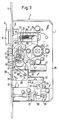
- FIG. 1 and 2 show a mortise door lock with a lock housing 7 delimited by side wall panels 1, 3 and a faceplate 5 arranged on the narrow side.
- a latch 9 is displaceably guided at right angles to the faceplate 5, the head 11 of which is not closer by one shown opening of the faceplate 5 emerges and the tail 13 is guided on a housing-fixed, in a slot 15 of the tail 13 engaging pin 17.
- a helical compression spring 19 is accommodated in the elongated hole 15, which is supported on the one hand on the pin 17 and on the other hand on the latch head end of the elongated hole 15 and prestresses the latch 9 in the direction of extension.
- the trap 9 can be retracted by means of a pivotally mounted in the lock housing 7 follower 21 by means of a lever, not shown, arranged on the inside of the door against the compression spring 19.
- the follower nut 21 has a finger 23 which extends over a shoulder 25 of the Trap tail 13 takes the trap 9 in the feed direction.
- a return spring 27 designed as a torsion coil spring holds the follower 21 in a rest position releasing the latch 9.
- the return spring 27 surrounds the follower nut 21 coaxially and requires hardly more space than the follower nut 21 itself.
- the lock housing 7 thus offers space for additional electronic components.
- a bolt 29 is slidably guided at right angles to the faceplate 5, which with its bolt head 31 passes through an opening of the faceplate 5 (not shown in more detail) and with its bolt tail 32 inside the lock housing 7 between two fixed pins 33, 35 is performed.
- the bolt 29 is drawn in and pushed out by an electric motor 37, which also pulls the latch 9 independently of the trigger actuation.
- the electric motor 37 is controlled by a control circuit, not shown, as described, for example, in DE-A-36 06 620.
- the controller responds to an electronically coded key (not shown in more detail) and for this purpose is connected to a reading device 40 which is arranged in a profile cylinder 38 of the door lock and which reads the information of the reading device 40 reading a key channel 39 of the profile cylinder 38 and accordingly provides electrical signals.
- the electric motor 37 drives a plate-shaped control part 43 via a gear transmission 41, which is linearly displaceable between the inside of the faceplate 5 and the pins 33, 35 at right angles to the direction of movement of both the latch 9 and the bolt 29.
- the gear 41 arranged between the latch 9 and the bolt 29 comprises a worm 45 which is seated on the output shaft of the electric motor 37 and which meshes with a worm wheel 49 mounted in the side wall plate 1 on the one hand and a bearing plate 47 fixed to the housing on the other hand.
- the worm wheel 49 drives a gear 53 via a pinion 51 which is arranged at the same axis is coupled to a pinion via an overload clutch 55, which is explained in more detail below and only transmits a predetermined torque.
- the pinion 57 engages in a rack toothing 59 running parallel to the faceplate 5, ie parallel to the direction of displacement of the control part 43 and driving the control part 43.
- the displacement movement of the control part 43, which is perpendicular to the direction of movement of the bolt 29, is transmitted to the bolt 29 via a slot 61 in the control part, which extends obliquely to both directions of movement and in which a pin 63 attached to the bolt 29 engages.
- Fig. 1 shows the door lock in the locked state, i.e. with bolt 29 fully pushed out of the lock housing 7, in which the control part 43 is placed in its position remote from the latch 9.
- Fig. 3 shows the door lock when the bolt 29 is retracted, but the latch 9 is pushed out, in which the electric motor 37 has brought the control part 43 closer to the latch 9 while the latch 29 is retracted.
- the slot 61 controlling the movement of the bolt 29 has a substantially Z-shape, with ends of a central portion 65 of the slot extending obliquely both to the direction of movement of the bolt 29 and to the direction of movement of the control part 43 61 Connect end sections 67, 69 running perpendicular to the direction of movement of the bolt 29.
- the end sections 67, 69 receive the pin 63 in the fully extended or fully inserted position of the bolt 29 and thus secure the bolt 29 being pushed in or pulled out.
- the control part 43 also controls the retraction movement of the catch 9.
- the catch 9 adjacent to the control part 43 carries a finger 75 which, when the bolt 29 is drawn in, moves into a recess in the catch tail 13 delimited by a shoulder 77.
- the rack teeth 59 extends over the required for the bolt movement Chen, parallel to the faceplate 5, straight line area and is bent over a concave toothing area 78 to a toothing area, in which the pin 63 of the locking head 31 enters the end portion 69 of the slot 61, bent towards the faceplate 5, so that with the rack toothing 59 meshing pinion 57 pivots the control part 43 around the pin 63 in the figures in a clockwise direction.
- the finger 75 takes, as shown in FIG. 4, the catch 9 in the feed direction.
- the pins 33, 35 guiding the bolt tail 32 are arranged such that the control part 43 for the pivoting movement between the pins 33 , 63 can tilt.
- the corner adjacent to the faceplate is provided with a flat 79. Since the rack toothing 59 runs in the curved area on the concave, ie on the outside, there is an increased reduction compared to the inside, which reduces the space requirement of the gear 41.
- the door lock can also be opened manually by pressing the lever handle, regardless of the electric motor drive, even if the bolt 29 is extended (panic function).
- 5 shows, by turning the handle arranged on the inside of the door, ie on the secured side of the door, the handle nut is pivoted, with which the finger 23 pulls the latch 9 over the shoulder 25 provided on the latch tail 13.
- a projection 81 formed on the follower 21 takes the control part 43 with it in the opening direction of the bolt 29.
- the projection 81 abuts a projection 83 of the control part 43, for example a riveted pin of the control part 43.
- the forced movement of the control part 43 is transmitted via the inclined surfaces of the slot 61 and the pin 63 to the bolt 29, which thereby moves it into its retracted position will.
- the overload clutch 55 arranged in the drive path of the transmission 41 between the electric motor 37 and the control part 43 is overcome when the control part 43 is operated manually and uncouples the self-locking worm 45.
- the overload clutch 55 also protects the electric motor 37 and the gear 43 against overload when the door lock is driven by an electric motor. Details of the overload clutch are explained below with reference to FIGS. 7 to 10.
- the electric motor 37 is controlled by an electronic circuit, not shown, which is accommodated on a circuit board 85 arranged on the side of the mechanical components of the door lock, between the side walls 1, 3 of the lock housing 7.
- the electronic circuit is connected to the reading device 40 of the profile cylinder 38 via several, for example six, lines.
- the profile cylinder 38 seated in a complementarily shaped insertion opening 87 of the two side parts 1, 3 is connected to the electronic circuit via a plug connection 89 in these feed lines.
- 6 shows details of the plug connection 89 and an associated holding device 91, which detachably holds the profile cylinder 38 in the insertion opening 87. In contrast to FIGS. 1 to 5, the holding device 91 is shown in a position that allows the profile cylinder 38 to be removed.
- the holding device 91 has a bearing block 93 held on the lock housing 7 with a recess 95 which is aligned with the insertion opening 87 and into which a web 99 projecting from the cylinder part 97 of the profile cylinder engages.
- the recess 95 surrounds the web 99 both laterally and along its longitudinal edge remote from the cylinder part 97 and ensures that the profile cylinder 38 is centered relative to the bearing block 93 and not by edges of the insertion opening 87 which surrounds the profile cylinder with a small oversize.
- a slide 103 is slidably guided on a guide pin 101 held in the bearing block 93, which slide on a bracket 105 has a strip with several, longitudinally of the profile cylinder 38 distributed sockets 107 of the connector 89 carries.
- the complementary connecting elements of the plug connection 89 are arranged as plug pins 109 completely within a recess of the web 99 of the profile cylinder 38 on a plug strip 111. The web 99 thus protects the sensitive connector pins 109
- the slide 103 can be displaced along the guide pin 101 by means of a threaded spindle 115 which is rotatably but axially fixed on the faceplate 5 by means of an abutment 113, the threaded pin 115 being screwed into a threaded bushing 117 which is fixed to the slide 103 in a rotationally fixed manner with a locking pin 119 is.
- the slide 103 carries a locking pin 121, to which a locking opening 123 is assigned on the web 99 of the profile cylinder 38 on the side of the connector pins 109.
- the locking pin 121 is displaceable in the slide 103 axially parallel to the guide pin 101 and carries an annular collar 127 in a chamber 125 of the slide 103. Between the annular collar 127 and an extension 129 of the threaded bushing 117 engaging in the chamber, a plate spring assembly 131 is clamped, which holds the locking bolt 121 biased towards the locking opening 123. The end of the locking pin 121 adjacent to the locking opening 123 is guided in a guide opening 133 of the bearing block 93.
- the guide pin 101 and the locking pin 121 guide the slide 103 against rotation and centered relative to the bearing block. Since the distance between the locking opening 123 and the adjacent end of the locking pin 121 in the position of the slide 103 releasing the profile cylinder 38 is smaller than the distance between the sockets 107 and the pins 109, the locking pin 121 snaps onto the profile cylinder 38 before the Plug connection 89 is closed. The locking pin 121 thus locks the profile cylinder 38 in a position in alignment with the sockets 107 and pins 109 before the contact is closed. Damage to the sockets 107 and the pins 109 due to misalignment is thus avoided.
- the latching force of the latching pin 121 is initially determined by the pretensioning of the plate spring assembly 131. In individual cases, the pretension may be too small to secure the profile cylinder 38 against being pulled out during operation.
- the block length of the fully compressed disc spring assembly 131 is selected so that the locking pin 121 engages immovably in the locking opening 123 in the end position of the slide 103 and is supported on the extension 129 of the threaded sleeve 117 via the fully compressed disc spring assembly 131.
- the plug connection 89 is closed, the length of the plug pins 109 being dimensioned such that they can compensate for movement tolerances of the sockets.
- a centering pin 139 provided with a ball point 137 is slidably guided in a bore 135 of the bearing block 93 which is coaxial with the locking pin 121 is biased by a compression spring 141 into a latching opening 143 of the web 99.
- the profile cylinder 38 can be inserted into the recess 95 of the bearing block 93 by overcoming the compression spring 141, the centering pin 139 ensuring that the profile cylinder 38 is pre-centered relative to the bearing block 93 and thus pre-centering the latching opening 123 relative to the latching pin 121.
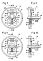
- the overload clutch 55 is designed as a snap-in clutch and couples the gear 53 to the pinion 57, which can be rotated relative to the gear 53 on a common axis 145.
- a recess 147 enclosing the axis 145 is seated radially to the axis 145 Slidably guided, a slide 149 with a locking projection 151 which is offset axially towards the pinion 57 and projects radially towards the axis 145.
- the locking projection 151 overlaps with the circumference of a circular disc 153, which is connected in a rotationally fixed manner to the pinion 57 via pins 154 and the slide 149 in the recess 147 axially fixed.
- the circular disk 153 has a latching recess 155 on its circumference, into which the latching projection 151 of the slide 149 engages in a prestressed manner by a spring 157.
- the projection 151 and the recess 155 have oblique edge edges when viewed in the circumferential direction, so that the projection 151 coupling the gear 53 with the pinion 57 is lifted out of the recess 155 against the force of the spring 157 against the force of the spring 157 and the overload clutch is triggered.
- 7 and 8 show the latched overload clutch, while the triggered state is shown in FIGS. 9 and 10.
- the slide 149 has an elongated hole 159 through which the axis 145 passes.
- the projection 151 is bent out from the inside of the elongated hole to the pinion 57, while a tab 161 is bent diametrically opposite the projection 151 into a radially extending chamber 163 of the gear 53.
- the chamber 163 contains the spring 157 which is supported between the tab 161 and an end wall of the chamber 163 adjacent to the axis 145.
- the overload clutch 55 is comparatively easy to assemble and requires only a few parts.
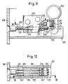
- the door lock in turn comprises a lock housing 207 formed from side walls 201, 203 and a faceplate 205, which has in its side walls 201, 203 for receiving a profile cylinder 209 provided with an electronic reading device, complementary to the profile shape of the profile cylinder 209, shaped insertion openings 211.
- a plurality of connector pins 215 are mechanically protected and electrically insulated in a recess on a web 213 of the profile cylinder which extends along the profile cylinder and extends transversely therefrom 217 of the web 213 housed.
- the plug pins 215 are assigned sockets 219, which in turn are insulated on a slide 221 which can be displaced in the plug-in direction of the plug pins 215.
- the carriage 221 is in turn attached to two bolts 223 which are parallel to one another and at a distance from one another Plug direction of the pins 215 extend and on the side facing away from the profile cylinder 209 of the slide 221 are slidably guided in a bearing block 225 fastened to the lock housing 207.
- the bolts 223 pass through the carriage 221 and project beyond the bushes 219 on the side facing the profile cylinder 209 in the sliding direction of the carriage 221.
- the sections projecting over the slide 221 toward the profile cylinder 209 form locking bolts 227, to which locking holes 229 are assigned in the web 213 of the profile cylinder.
- the locking bolts 227 engage in the locking holes 229 and align the web 213 relative to the slide 221 before the plug pins 215 move into the sockets 219. In this way, damage to the connector contacts are reliably avoided in spite of the normally slight play of the profile cylinder 209 in the insertion openings 211.
- an adjusting screw 231 accessible from the faceplate 205 can be rotated, but by means of a securing pin 233 axially fixed.
- the set screw 231 engages in the manner of a spindle drive in a threaded opening of the slide 221.
- the slide 221 can be moved by means of the set screw 231 from the faceplate 205 against the web 213 of the profile cylinder.
- a stop surface 235 provided on the carriage 221 clamps the profile cylinder against the edges of the insertion openings 211.
- the holding force need not be particularly great since the profile cylinder 209 is secured against being pulled out of the insertion openings 211 by the bolts 223.
- elongated guide cheeks are integrally formed on the side of the slide 221 facing away from the locking bolts 227.
- the guide cheeks are guided in grooves in the bearing block 225 and enclose the bearing block in a fork-like manner between them.
Landscapes
- Engineering & Computer Science (AREA)
- Mechanical Engineering (AREA)
- Lock And Its Accessories (AREA)
- Details Of Connecting Devices For Male And Female Coupling (AREA)
- Footwear And Its Accessory, Manufacturing Method And Apparatuses (AREA)
- Pharmaceuticals Containing Other Organic And Inorganic Compounds (AREA)
- Acyclic And Carbocyclic Compounds In Medicinal Compositions (AREA)
- Supporting Of Heads In Record-Carrier Devices (AREA)
Priority Applications (4)
| Application Number | Priority Date | Filing Date | Title |
|---|---|---|---|
| CA 2000738 CA2000738A1 (fr) | 1988-10-17 | 1989-10-16 | Serrure |
| JP26829789A JPH02176082A (ja) | 1988-10-17 | 1989-10-17 | 錠 |
| FI894918A FI88329C (fi) | 1988-10-17 | 1989-10-17 | Laos |
| FI923917A FI923917A7 (fi) | 1988-10-17 | 1992-09-01 | Laos |
Applications Claiming Priority (2)
| Application Number | Priority Date | Filing Date | Title |
|---|---|---|---|
| DE3835349 | 1988-10-17 | ||
| DE3835349A DE3835349A1 (de) | 1988-10-17 | 1988-10-17 | Schloss |
Related Child Applications (2)
| Application Number | Title | Priority Date | Filing Date |
|---|---|---|---|
| EP19930104697 Division EP0551147A3 (fr) | 1988-10-17 | 1989-09-28 | Serrure actionnée par un moteur électrique |
| EP93104697.3 Division-Into | 1993-03-22 |
Publications (3)
| Publication Number | Publication Date |
|---|---|
| EP0364781A2 true EP0364781A2 (fr) | 1990-04-25 |
| EP0364781A3 EP0364781A3 (fr) | 1991-04-10 |
| EP0364781B1 EP0364781B1 (fr) | 1994-07-13 |
Family
ID=6365311
Family Applications (2)
| Application Number | Title | Priority Date | Filing Date |
|---|---|---|---|
| EP19930104697 Ceased EP0551147A3 (fr) | 1988-10-17 | 1989-09-28 | Serrure actionnée par un moteur électrique |
| EP89117975A Expired - Lifetime EP0364781B1 (fr) | 1988-10-17 | 1989-09-28 | Serrure |
Family Applications Before (1)
| Application Number | Title | Priority Date | Filing Date |
|---|---|---|---|
| EP19930104697 Ceased EP0551147A3 (fr) | 1988-10-17 | 1989-09-28 | Serrure actionnée par un moteur électrique |
Country Status (5)
| Country | Link |
|---|---|
| US (1) | US5044184A (fr) |
| EP (2) | EP0551147A3 (fr) |
| AT (1) | ATE108505T1 (fr) |
| DE (2) | DE3835349A1 (fr) |
| ES (1) | ES2059663T3 (fr) |
Cited By (5)
| Publication number | Priority date | Publication date | Assignee | Title |
|---|---|---|---|---|
| EP0482588A1 (fr) * | 1990-10-23 | 1992-04-29 | Aug. Winkhaus GmbH & Co. KG | Serrure de porte commandée par moteur électrique |
| EP0559157A1 (fr) * | 1992-03-06 | 1993-09-08 | Aug. Winkhaus GmbH & Co. KG | Cylindre de fermeture électronique raccordable sur un connecteur à fiche |
| EP0585735A1 (fr) * | 1992-08-19 | 1994-03-09 | Eberhard Gawehn | Serrure de fixation pour cylindre d'un verrou de sécurité |
| WO1995021310A1 (fr) * | 1994-02-04 | 1995-08-10 | Evva-Werk Spezialerzeugung Von Zylinder- Und Sicherheitsschlössern Gesellschaft Mbh & Co. Kommanditgesellschaft | Dispositif de contact electrique |
| WO2001002679A1 (fr) * | 1999-07-02 | 2001-01-11 | Claes Magnusson | Serrure |
Families Citing this family (32)
| Publication number | Priority date | Publication date | Assignee | Title |
|---|---|---|---|---|
| AT400062B (de) * | 1993-03-26 | 1995-09-25 | Roto Frank Eisenwaren | Mehrriegelschloss |
| DE19609483C1 (de) * | 1996-03-12 | 1997-04-30 | Dorma Gmbh & Co Kg | Einsteckschloß |
| US5782118A (en) * | 1996-07-16 | 1998-07-21 | Schlage Lock Company | Lockset with motorized system for locking and unlocking |
| DE19701761C1 (de) * | 1997-01-20 | 1998-04-16 | Fuss Fritz Gmbh & Co | Selbstverriegelndes Schloß |
| DE19707762C1 (de) * | 1997-02-26 | 1998-04-16 | Fuss Fritz Gmbh & Co | Sicherheitsschloß |
| AU757887B2 (en) * | 1998-11-03 | 2003-03-13 | Azoteq (Pty) Ltd. | Electric lock |
| DE19957061A1 (de) * | 1999-11-26 | 2001-05-31 | Kiekert Ag | Kraftfahrzeugtürverschluss |
| AU2002953027A0 (en) * | 2002-11-29 | 2002-12-19 | Inovec Pty Ltd I | A lock slider body |
| AUPQ757600A0 (en) * | 2000-05-18 | 2000-06-08 | Keightley, Kym John | Dual locking mechanism |
| US6354121B1 (en) * | 2000-07-21 | 2002-03-12 | Harrow Products, Inc. | Mortise lockset with internal clutch |
| US6619705B2 (en) | 2002-01-04 | 2003-09-16 | Schlage Lock Company | Mortise lockset with internal clutch |
| US6871451B2 (en) * | 2002-03-27 | 2005-03-29 | Newell Operating Company | Multipoint lock assembly |
| US6725693B2 (en) * | 2002-08-30 | 2004-04-27 | Jer Ming Yu | Door lock with a clutch having a cam-styled axle sleeve |
| US6733050B1 (en) * | 2002-11-12 | 2004-05-11 | Shyang Feng Electric & Machinery Co., Ltd. | Bolt dock for door lock |
| US7010946B2 (en) * | 2003-05-19 | 2006-03-14 | Truth Hardware Corporation | Latch apparatus |
| US20060123859A1 (en) * | 2004-12-13 | 2006-06-15 | Gonzalez Fermin G | Mortise lock with automatic projection of dead bolt |
| US7445254B2 (en) * | 2005-04-29 | 2008-11-04 | Truth Hardware Corporation | Dual dead bolt latch |
| ITTO20050772A1 (it) * | 2005-10-31 | 2007-05-01 | Savio Spa | Dispositivo di riallineamento della serratura di un serramento scorrevole |
| FI120109B (fi) * | 2006-05-02 | 2009-06-30 | Abloy Oy | Lukkorunko |
| US7946080B2 (en) * | 2007-01-29 | 2011-05-24 | Newell Operating Company | Lock assembly |
| DE202007017139U1 (de) * | 2007-12-06 | 2009-04-09 | Kfv Karl Fliether Gmbh & Co. Kg | Schloss |
| US7533551B1 (en) * | 2008-03-03 | 2009-05-19 | Ming-I Liu | Door lock with key cylinder |
| US8671724B2 (en) * | 2010-04-19 | 2014-03-18 | Adams Rite Manufacturing Co. | Multiple access door lock mechanism |
| FR2974835B1 (fr) * | 2011-05-03 | 2013-05-24 | Metalux | Serrure encastrable |
| DE102012106722B4 (de) * | 2012-07-24 | 2017-11-30 | K.A. Schmersal Holding Gmbh & Co. Kg | Zuhaltung für eine Zugangsschutzvorrichtung mit einer Hilfsentriegelung |
| KR101480508B1 (ko) * | 2013-03-11 | 2015-01-08 | 삼성에스디에스 주식회사 | 도어락 모티스 |
| US9422742B2 (en) | 2013-04-09 | 2016-08-23 | Keith Pardoe | Systems, devices, and/or methods for managing swinging doors |
| SE543452C2 (en) * | 2018-08-23 | 2021-02-23 | Stendals El Ab | Locking device with a movable actuator for selecting an active side of a door, accessible from a side facing away from the locking bolt |
| IT201900020925A1 (it) * | 2019-11-12 | 2021-05-12 | Bonaiti Serrature Spa | Serratura antipanico con dispositivo elettronico di controllo-accessi |
| CN110821375B (zh) * | 2019-12-07 | 2025-05-06 | 刘毅 | 一种窗锁机构的改进定位安装结构 |
| DE102022000136B4 (de) | 2022-01-15 | 2023-12-07 | Rudolf Dein | Einsteck- oder Aufschraubschloss mit einem in diesem integrierten Befestigungselement für einen eine Gewindebohrung aufweisenden Profilzylinder |
| DE102024123877A1 (de) * | 2024-08-21 | 2026-02-26 | Rittal Gmbh & Co. Kg | Verschlusssystem zum Sichern eines Schließzylinders in einem Schließelement, ein Schließelement sowie ein entsprechendes Verfahren |
Family Cites Families (20)
| Publication number | Priority date | Publication date | Assignee | Title |
|---|---|---|---|---|
| DE1033082B (de) * | 1952-06-05 | 1958-06-26 | C Ed Schulte Ag Schloss U Meta | Schloss, insbesondere Tuerschloss mit Fallenwechsel |
| US3148525A (en) * | 1963-04-15 | 1964-09-15 | Sidney I Durant | Electrically operated door lock |
| US3242706A (en) * | 1963-11-27 | 1966-03-29 | Yale & Towne Inc | Lock with deadlocking latchbolt |
| US3266276A (en) * | 1964-08-26 | 1966-08-16 | Yulkowski Leon | Door lock |
| US3672714A (en) * | 1970-09-28 | 1972-06-27 | Eaton Corp | Mortise lock with multiple functions |
| US3769822A (en) * | 1972-06-12 | 1973-11-06 | Gen Lock Co | Door lock |
| DE2361307C3 (de) * | 1973-12-08 | 1979-01-04 | Eaton Gmbh, 5620 Velbert | Panik-Hauptschloß mit FaUen-Nebenverschlüssen |
| US3992908A (en) * | 1974-12-12 | 1976-11-23 | International Top Security Corporation | Door lock housing assembly and releasable catch |
| IL47557A (en) * | 1975-06-25 | 1979-09-30 | Assaraf S | Security lock |
| DE2919201C2 (de) * | 1979-05-12 | 1984-08-23 | Karl Fliether GmbH & Co, 5620 Velbert | Zahnradantrieb in einem schließzylinderbetätigbaren Treibstangenschloß |
| US4572556A (en) * | 1983-10-24 | 1986-02-25 | Best Lock Corporation | Mortise lock |
| DE3514147A1 (de) * | 1985-04-19 | 1986-10-23 | BKS GmbH, 5620 Velbert | Elektrisch steuerbares tuerschloss mit schliesszylinder |
| DE3620799A1 (de) * | 1985-08-12 | 1987-02-19 | Bauer Kaba Ag | Multifunktions-einsteckschloss |
| CH668451A5 (de) * | 1985-10-24 | 1988-12-30 | Bauer Kaba Ag | Vorrichtung zur elektromagnetischen verriegelung an einem schliesszylinder fuer ein mechanisch/elektronisches schliess-system. |
| FI79168C (fi) * | 1985-12-05 | 1991-03-26 | Waertsilae Oy Ab | Doerrlaos. |
| DE3606531A1 (de) * | 1986-02-28 | 1987-09-03 | Fliether Karl Gmbh & Co | Schliesszylinder mit antrieb |
| DE3606620A1 (de) * | 1986-02-28 | 1987-09-03 | Winkhaus Fa August | Elektronisches tuerschloss |
| JPH0765417B2 (ja) * | 1986-04-14 | 1995-07-19 | 基博 五反田 | 錠装置 |
| DE3707284A1 (de) * | 1987-03-06 | 1988-09-15 | Winkhaus Fa August | Elektronisches tuerschloss |
| DE3742153A1 (de) * | 1987-12-11 | 1989-06-22 | Winkhaus Fa August | Elektromotorisch angetriebenes tuerschloss |
-
1988
- 1988-10-17 DE DE3835349A patent/DE3835349A1/de not_active Ceased
-
1989
- 1989-09-28 ES ES89117975T patent/ES2059663T3/es not_active Expired - Lifetime
- 1989-09-28 AT AT89117975T patent/ATE108505T1/de not_active IP Right Cessation
- 1989-09-28 DE DE58908039T patent/DE58908039D1/de not_active Expired - Fee Related
- 1989-09-28 EP EP19930104697 patent/EP0551147A3/fr not_active Ceased
- 1989-09-28 EP EP89117975A patent/EP0364781B1/fr not_active Expired - Lifetime
- 1989-10-16 US US07/421,653 patent/US5044184A/en not_active Expired - Fee Related
Cited By (8)
| Publication number | Priority date | Publication date | Assignee | Title |
|---|---|---|---|---|
| EP0482588A1 (fr) * | 1990-10-23 | 1992-04-29 | Aug. Winkhaus GmbH & Co. KG | Serrure de porte commandée par moteur électrique |
| EP0559157A1 (fr) * | 1992-03-06 | 1993-09-08 | Aug. Winkhaus GmbH & Co. KG | Cylindre de fermeture électronique raccordable sur un connecteur à fiche |
| DE4234361A1 (de) * | 1992-03-06 | 1993-09-23 | Winkhaus Fa August | Ueber eine steckerverbindung anschliessbarer elektronischer schliesszylinder |
| US5373718A (en) * | 1992-03-06 | 1994-12-20 | Aug. Winkhaus Gmbh & Co. Kg | Electronic lock cylinder connectable by a plug connector |
| EP0585735A1 (fr) * | 1992-08-19 | 1994-03-09 | Eberhard Gawehn | Serrure de fixation pour cylindre d'un verrou de sécurité |
| WO1995021310A1 (fr) * | 1994-02-04 | 1995-08-10 | Evva-Werk Spezialerzeugung Von Zylinder- Und Sicherheitsschlössern Gesellschaft Mbh & Co. Kommanditgesellschaft | Dispositif de contact electrique |
| WO2001002679A1 (fr) * | 1999-07-02 | 2001-01-11 | Claes Magnusson | Serrure |
| US6213523B1 (en) | 1999-07-02 | 2001-04-10 | Claes Magnusson | Lock |
Also Published As
| Publication number | Publication date |
|---|---|
| ES2059663T3 (es) | 1994-11-16 |
| ATE108505T1 (de) | 1994-07-15 |
| DE58908039D1 (de) | 1994-08-18 |
| DE3835349A1 (de) | 1990-04-19 |
| EP0551147A2 (fr) | 1993-07-14 |
| EP0364781A3 (fr) | 1991-04-10 |
| US5044184A (en) | 1991-09-03 |
| EP0551147A3 (fr) | 1993-07-28 |
| EP0364781B1 (fr) | 1994-07-13 |
Similar Documents
| Publication | Publication Date | Title |
|---|---|---|
| EP0364781B1 (fr) | Serrure | |
| DE112009000529B4 (de) | Schloss mit drehbarer Sperrklinke | |
| DE19961975C1 (de) | Verriegelungsvorrichtung | |
| EP2491208A1 (fr) | Dispositif poignée affleurant pour portière de véhicule à moteur | |
| DE102014209543B4 (de) | Türverriegelungsvorrichtung | |
| DE102014219037A1 (de) | Parksperreneinrichtung für ein Kraftfahrzeug | |
| DE102018123949A1 (de) | Betätigungsvorrichtung | |
| DE112018004506T5 (de) | Anschluss-Sperraktuatorvorrichtung für Fahrzeugeingangsanschluss | |
| DE102011055963B4 (de) | Ladedose mit Hebelgetriebe für eine Steckverbindung zur Aufladung eines Elektrofahrzeuges | |
| DE3924209C2 (de) | Türschloß | |
| DE19645058C1 (de) | Selbstjustierender Stößelschalter, insbesondere KFZ-Bremslichtschalter | |
| DE29603652U1 (de) | Beschlag für ein Schloß | |
| DE4436617C1 (de) | Entriegelungsvorrichtung für einen Kraftfahrzeugtürverschluß | |
| EP0320008B1 (fr) | Serrure à moteur électrique | |
| EP4438836B1 (fr) | Système de fermeture et porte ou fenêtre dotée d'un tel système de fermeture | |
| DE102021102477A1 (de) | Leiteranschlussklemme | |
| DE112018004978T5 (de) | Anschluss-Sperraktuatorvorrichtung für Fahrzeugeingangsanschluss | |
| EP0482588A1 (fr) | Serrure de porte commandée par moteur électrique | |
| DE3642915A1 (de) | Elektromotorisches stellelement | |
| DE69218110T2 (de) | Vorrichtung zur mechanischen Steuerung von elektrischen Lastschaltern und dergleichen, vorsehen für Verrieglungs-, Blockierungs-, und Signalisierungsmittel | |
| DE60012609T2 (de) | Elektrisch oder mechanisch betätigbares Schloss | |
| EP3670799A1 (fr) | Dispositif de verrouillage | |
| DE19702251C2 (de) | Zentralverriegelungsstellelement für Türen oder Klappen von Kraftfahrzeugen | |
| EP1920126A1 (fr) | Dispositif d'actionnement d'une serrure | |
| DE4221671C2 (de) | Stellelement für die Entriegelung einer Schließeinrichtung |
Legal Events
| Date | Code | Title | Description |
|---|---|---|---|
| PUAI | Public reference made under article 153(3) epc to a published international application that has entered the european phase |
Free format text: ORIGINAL CODE: 0009012 |
|
| AK | Designated contracting states |
Kind code of ref document: A2 Designated state(s): AT BE CH DE ES FR IT LI NL SE |
|
| PUAL | Search report despatched |
Free format text: ORIGINAL CODE: 0009013 |
|
| AK | Designated contracting states |
Kind code of ref document: A3 Designated state(s): AT BE CH DE ES FR IT LI NL SE |
|
| 17P | Request for examination filed |
Effective date: 19910809 |
|
| 17Q | First examination report despatched |
Effective date: 19921117 |
|
| GRAA | (expected) grant |
Free format text: ORIGINAL CODE: 0009210 |
|
| AK | Designated contracting states |
Kind code of ref document: B1 Designated state(s): AT BE CH DE ES FR IT LI NL SE |
|
| REF | Corresponds to: |
Ref document number: 108505 Country of ref document: AT Date of ref document: 19940715 Kind code of ref document: T |
|
| XX | Miscellaneous (additional remarks) |
Free format text: TEILANMELDUNG 93104697.3 EINGEREICHT AM 28/09/89. |
|
| REF | Corresponds to: |
Ref document number: 58908039 Country of ref document: DE Date of ref document: 19940818 |
|
| ITF | It: translation for a ep patent filed | ||
| PGFP | Annual fee paid to national office [announced via postgrant information from national office to epo] |
Ref country code: SE Payment date: 19940906 Year of fee payment: 6 |
|
| ET | Fr: translation filed | ||
| PGFP | Annual fee paid to national office [announced via postgrant information from national office to epo] |
Ref country code: CH Payment date: 19940909 Year of fee payment: 6 |
|
| PGFP | Annual fee paid to national office [announced via postgrant information from national office to epo] |
Ref country code: BE Payment date: 19940914 Year of fee payment: 6 |
|
| PGFP | Annual fee paid to national office [announced via postgrant information from national office to epo] |
Ref country code: FR Payment date: 19940915 Year of fee payment: 6 |
|
| PGFP | Annual fee paid to national office [announced via postgrant information from national office to epo] |
Ref country code: ES Payment date: 19940916 Year of fee payment: 6 |
|
| PGFP | Annual fee paid to national office [announced via postgrant information from national office to epo] |
Ref country code: AT Payment date: 19940928 Year of fee payment: 6 |
|
| PGFP | Annual fee paid to national office [announced via postgrant information from national office to epo] |
Ref country code: NL Payment date: 19940930 Year of fee payment: 6 |
|
| REG | Reference to a national code |
Ref country code: ES Ref legal event code: FG2A Ref document number: 2059663 Country of ref document: ES Kind code of ref document: T3 |
|
| EAL | Se: european patent in force in sweden |
Ref document number: 89117975.6 |
|
| PLBE | No opposition filed within time limit |
Free format text: ORIGINAL CODE: 0009261 |
|
| STAA | Information on the status of an ep patent application or granted ep patent |
Free format text: STATUS: NO OPPOSITION FILED WITHIN TIME LIMIT |
|
| 26N | No opposition filed | ||
| PG25 | Lapsed in a contracting state [announced via postgrant information from national office to epo] |
Ref country code: AT Effective date: 19950928 |
|
| PG25 | Lapsed in a contracting state [announced via postgrant information from national office to epo] |
Ref country code: SE Effective date: 19950929 Ref country code: ES Free format text: LAPSE BECAUSE OF THE APPLICANT RENOUNCES Effective date: 19950929 |
|
| PGFP | Annual fee paid to national office [announced via postgrant information from national office to epo] |
Ref country code: DE Payment date: 19950929 Year of fee payment: 7 |
|
| PG25 | Lapsed in a contracting state [announced via postgrant information from national office to epo] |
Ref country code: LI Effective date: 19950930 Ref country code: CH Effective date: 19950930 Ref country code: BE Effective date: 19950930 |
|
| BERE | Be: lapsed |
Owner name: AUG. WINKHAUS G.M.B.H. & CO. K.G. Effective date: 19950930 |
|
| PG25 | Lapsed in a contracting state [announced via postgrant information from national office to epo] |
Ref country code: NL Effective date: 19960401 |
|
| REG | Reference to a national code |
Ref country code: CH Ref legal event code: PL |
|
| PG25 | Lapsed in a contracting state [announced via postgrant information from national office to epo] |
Ref country code: FR Effective date: 19960531 |
|
| NLV4 | Nl: lapsed or anulled due to non-payment of the annual fee |
Effective date: 19960401 |
|
| EUG | Se: european patent has lapsed |
Ref document number: 89117975.6 |
|
| REG | Reference to a national code |
Ref country code: FR Ref legal event code: ST |
|
| PG25 | Lapsed in a contracting state [announced via postgrant information from national office to epo] |
Ref country code: DE Effective date: 19970603 |
|
| REG | Reference to a national code |
Ref country code: ES Ref legal event code: FD2A Effective date: 19991007 |
|
| PG25 | Lapsed in a contracting state [announced via postgrant information from national office to epo] |
Ref country code: IT Free format text: LAPSE BECAUSE OF NON-PAYMENT OF DUE FEES;WARNING: LAPSES OF ITALIAN PATENTS WITH EFFECTIVE DATE BEFORE 2007 MAY HAVE OCCURRED AT ANY TIME BEFORE 2007. THE CORRECT EFFECTIVE DATE MAY BE DIFFERENT FROM THE ONE RECORDED. Effective date: 20050928 |