EP0364809A1 - Elément pour tempérer des locaux à monter au mur ou au plafond - Google Patents
Elément pour tempérer des locaux à monter au mur ou au plafond Download PDFInfo
- Publication number
- EP0364809A1 EP0364809A1 EP89118303A EP89118303A EP0364809A1 EP 0364809 A1 EP0364809 A1 EP 0364809A1 EP 89118303 A EP89118303 A EP 89118303A EP 89118303 A EP89118303 A EP 89118303A EP 0364809 A1 EP0364809 A1 EP 0364809A1
- Authority
- EP
- European Patent Office
- Prior art keywords
- profile
- room temperature
- temperature control
- control element
- element according
- Prior art date
- Legal status (The legal status is an assumption and is not a legal conclusion. Google has not performed a legal analysis and makes no representation as to the accuracy of the status listed.)
- Granted
Links
- 238000005496 tempering Methods 0.000 title abstract 2
- 238000003780 insertion Methods 0.000 claims description 4
- 230000037431 insertion Effects 0.000 claims description 4
- 239000006163 transport media Substances 0.000 claims description 4
- 238000001816 cooling Methods 0.000 description 2
- 229910052782 aluminium Inorganic materials 0.000 description 1
- XAGFODPZIPBFFR-UHFFFAOYSA-N aluminium Chemical compound [Al] XAGFODPZIPBFFR-UHFFFAOYSA-N 0.000 description 1
- 230000005540 biological transmission Effects 0.000 description 1
- 230000015572 biosynthetic process Effects 0.000 description 1
- 238000005253 cladding Methods 0.000 description 1
- 239000004020 conductor Substances 0.000 description 1
- 230000000694 effects Effects 0.000 description 1
- 210000003608 fece Anatomy 0.000 description 1
- 238000010438 heat treatment Methods 0.000 description 1
- 238000009434 installation Methods 0.000 description 1
- 229910052751 metal Inorganic materials 0.000 description 1
- 239000002184 metal Substances 0.000 description 1
- 230000000630 rising effect Effects 0.000 description 1
- XLYOFNOQVPJJNP-UHFFFAOYSA-N water Substances O XLYOFNOQVPJJNP-UHFFFAOYSA-N 0.000 description 1
Images

Classifications
-
- F—MECHANICAL ENGINEERING; LIGHTING; HEATING; WEAPONS; BLASTING
- F24—HEATING; RANGES; VENTILATING
- F24D—DOMESTIC- OR SPACE-HEATING SYSTEMS, e.g. CENTRAL HEATING SYSTEMS; DOMESTIC HOT-WATER SUPPLY SYSTEMS; ELEMENTS OR COMPONENTS THEREFOR
- F24D3/00—Hot-water central heating systems
- F24D3/12—Tube and panel arrangements for ceiling, wall, or underfloor heating
- F24D3/16—Tube and panel arrangements for ceiling, wall, or underfloor heating mounted on, or adjacent to, a ceiling, wall or floor
- F24D3/165—Suspended radiant heating ceiling
-
- Y—GENERAL TAGGING OF NEW TECHNOLOGICAL DEVELOPMENTS; GENERAL TAGGING OF CROSS-SECTIONAL TECHNOLOGIES SPANNING OVER SEVERAL SECTIONS OF THE IPC; TECHNICAL SUBJECTS COVERED BY FORMER USPC CROSS-REFERENCE ART COLLECTIONS [XRACs] AND DIGESTS
- Y02—TECHNOLOGIES OR APPLICATIONS FOR MITIGATION OR ADAPTATION AGAINST CLIMATE CHANGE
- Y02B—CLIMATE CHANGE MITIGATION TECHNOLOGIES RELATED TO BUILDINGS, e.g. HOUSING, HOUSE APPLIANCES OR RELATED END-USER APPLICATIONS
- Y02B30/00—Energy efficient heating, ventilation or air conditioning [HVAC]
Definitions
- the present invention relates to a room temperature control element for mounting in particular on walls and / or ceilings, consisting of a heat transfer profile and at least one pipeline for a heat transport medium which runs within the heat transfer profile and is in heat-conducting contact therewith.
- Such a room temperature control element is known from DE-GM 86 60 018.
- this room temperature control element has proven to be excellent, but it is designed as a frame profile and can therefore be arranged in particular in the area of window or door frames. It would also be possible to mount the frame profile on walls or ceilings, but this would not cover the entire surface.
- the present invention is therefore based on the object of a room temperature control element of the generic type to design that it is particularly well suited for a full covering of wall and / or ceiling surfaces.
- the heat transfer profile has a laterally open groove on one long side and a spring which is adapted to the groove and extends in the plane of the groove away from the tongue on the opposite long side.
- the room temperature control element according to the invention forms a surface cladding element, wherein a plurality of parallel room temperature control elements which are fastened to the respective surface by suitable fastening means are connected to one another via the tongue and groove connections according to the invention, i.e. interlock.
- the room temperature control element according to the invention is particularly well suited for creating so-called suspended ceilings.
- the room temperature control element advantageously has at least one mounting profile in the profile region of the heat transfer profile lying between the groove and the tongue, into which the fastening elements fastened to the wall or the ceiling engage in a non-positive and / or positive manner.
- the heat transfer profile can have, for example, bead-shaped profile sections running in the longitudinal direction of the profile. Through a ceiling covering (abge suspended ceiling), cooling in particular can be implemented, the heat rising in the room being transferred to the pipeline via the heat transfer profile and being dissipated by the heat transport medium flowing through the pipeline.
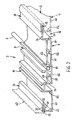
- a room temperature control element 2 consists of a heat transfer profile 4 made of a good heat-conducting material, in particular metal, such as aluminum.
- a heat transport medium for example water, flows through this pipe 6 and, in the example shown, lies directly or via a heat contact surface which is semicircular in cross section thermal contact layer, not shown.
- the heat contact surface is adapted to the diameter of the pipeline 6 by a semicircular in its base region Receiving groove 8 of a partial profile 10 formed integrally with the heat transfer profile 4. In this case, the pipeline 6 is held in its position shown by holding parts, not shown.
- the heat transfer profile 4 now has a laterally open groove 12 and on the opposite long side a matched to the groove 12, extending in the plane of the groove 12 away from this tongue 14. Furthermore, the heat transfer profile 4 has in between the groove 12 and the tongue 14 lying profile area at least one, preferably integrally formed with the heat transfer profile 4 mounting profile 16, in which fasteners 18 which can be fastened to a wall or ceiling surface, not shown, in particular engage in a form-fitting manner.
- the heat transfer profile 4 is formed with a flat, essentially U-shaped cross section from a surface wall 20 parallel to the wall or ceiling to be clad and two side walls 22 and 24 approximately perpendicular to this.
- the groove 12 is preferably formed in that the one side wall 22 into a cross-sectionally C-shaped profile section 26 defining the groove 12 with two spaced apart legs 28 and 30 parallel to the surface wall 20 and one connecting to the surface wall 20 vertical web 32 merges. As shown, the leg 28 is connected to the side wall 22 in the region of its free end.
- the other side wall 24 goes approximately at right angles into a profile web forming the tongue 14, the thickness of which corresponds approximately to the inside width of the groove 12, ie the inside distance between the legs 28, 30 of the profile section 26 34 over.
- the length of the profile web 34 ⁇ measured across the longitudinal axis of the profile is the depth of the groove 12, so that the side walls 24 and 22 can come to rest against each other.
- the profile web 34 measured transversely to the longitudinal axis of the profile, has a greater length than the depth of the groove 12.
- the mounting profile 16 consists of two webs 38 which run parallel in the longitudinal direction of the profile and are arranged approximately perpendicular to the surface wall 20, each of which has an insertion slot 40 between its free ends facing one another and arranged parallel to the surface wall 20 enclosing retaining webs 42 and embracing the fasteners 18.
- fastening elements 18 can be used, each of which has a, for example plate-shaped, holding part 44 adapted to the cross section enclosed by the webs 38 and the holding webs 42.
- Each of these holding parts 44 preferably has a length which corresponds approximately to the clear distance between the webs 38 of the mounting profile 16, and a width which is ⁇ the width of the Insertion slot 40 between the free ends of the holding webs 42 is.
- the holding parts 44 can either be pushed into the receiving groove of the mounting profile 16 in the direction of the arrow 46 in the longitudinal direction of the profile, or can be guided through the insertion slot 40 from a direction perpendicular to the surface wall 20, ie in the direction of the arrow 48.
- the holding part 44 is subsequently rotated by 90 ° in the direction of the double arrow 50.
- the heat transfer profile 4 has, in particular in the area of the surface wall 20, at least one bead-shaped profile section 52 running in the longitudinal direction of the profile , so that here too an open groove 58 is formed in the direction of the room, through which the effective heat transfer surface advantageously increases.
- the mounting profile 16 described above is arranged in the region of the bead-shaped profile section 52, the webs 38 of the mounting profile 16 being formed as extensions of the wall webs 54 of the bead-shaped profile section 52.
- an attachment bracket 60 provided according to the invention and attachable to the wall or ceiling is also shown in dashed lines.
- This mounting bracket 60 serves to hold the side edge of the outermost room temperature control element and for this purpose either engages with a leg in the groove 12 or engages with a receiving groove formed in the region of the leg the tongue 14 of the respective heat transfer profile 4.
- Only the first one is shown in the drawing Alternative shown.
- FIG. 2 shows an advantageous further development of the invention, the same parts being identified with the same reference numerals as in FIG. 1.
- a connecting wall 62 or 64 is arranged between the partial profile 10 and on the one hand the side wall 24 and on the other hand the wall web 54 of the bead-shaped profile section 52.
- These connecting walls 62, 64 preferably run parallel to the surface wall 20 at a distance from them and are formed in one piece with the heat transfer profile 4.
- the partial profile 10 and the side wall 24 are spaced relatively far apart.
- the surface wall 20 is connected to the connecting wall 62 via a web wall 66 arranged perpendicular to the latter.
- a web wall 66 can be arranged analogously to this, as is shown in broken lines in FIG. 2.
- the web wall 66 is also formed in one piece with the heat transfer profile 4.
- Both the connecting walls 62, 64 and the web wall (s) 66 preferably extend over the entire length of the heat transfer profile 4, but it is also within the scope of the invention to have only short portions of these walls 62, 64 and which are spaced apart from one another by gaps in the longitudinal direction of the profile 66 to be provided.
- the heat distribution ie the heat gradient within the room temperature control element 2 according to the invention is significantly improved, since the heat is also provided not only via the surface wall 20 but also via the connecting wall dungs 62, 64 and - if available - also distributed or guided over the web wall (s) 66.
Landscapes
- Engineering & Computer Science (AREA)
- Physics & Mathematics (AREA)
- Thermal Sciences (AREA)
- Chemical & Material Sciences (AREA)
- Combustion & Propulsion (AREA)
- Mechanical Engineering (AREA)
- General Engineering & Computer Science (AREA)
- Building Environments (AREA)
- Heat-Exchange Devices With Radiators And Conduit Assemblies (AREA)
Priority Applications (1)
| Application Number | Priority Date | Filing Date | Title |
|---|---|---|---|
| AT89118303T ATE103385T1 (de) | 1988-10-21 | 1989-10-03 | Raumtemperierungselement zur montage an wandund deckenflaechen. |
Applications Claiming Priority (4)
| Application Number | Priority Date | Filing Date | Title |
|---|---|---|---|
| DE8813230U | 1988-10-21 | ||
| DE8813230U DE8813230U1 (de) | 1988-10-21 | 1988-10-21 | Raumtemperierungselement zur Montage an Wand- und Deckenflächen |
| DE8815347U DE8815347U1 (de) | 1988-10-21 | 1988-12-10 | Raumtemperierungselement zur Montage an Wand- und Deckenflächen |
| DE8815347U | 1988-12-10 |
Publications (2)
| Publication Number | Publication Date |
|---|---|
| EP0364809A1 true EP0364809A1 (fr) | 1990-04-25 |
| EP0364809B1 EP0364809B1 (fr) | 1994-03-23 |
Family
ID=25953665
Family Applications (1)
| Application Number | Title | Priority Date | Filing Date |
|---|---|---|---|
| EP89118303A Expired - Lifetime EP0364809B1 (fr) | 1988-10-21 | 1989-10-03 | Elément pour tempérer des locaux à monter au mur ou au plafond |
Country Status (2)
| Country | Link |
|---|---|
| EP (1) | EP0364809B1 (fr) |
| DE (2) | DE8815347U1 (fr) |
Cited By (3)
| Publication number | Priority date | Publication date | Assignee | Title |
|---|---|---|---|---|
| GB2284661B (en) * | 1993-11-04 | 1997-11-12 | Keymer Michael D | Safety cover |
| US20080264602A1 (en) * | 2007-04-27 | 2008-10-30 | Dean Talbott Newberry | Radiant heating and cooling panel |
| DE102017110811A1 (de) * | 2017-05-18 | 2018-11-22 | Dula-Werke Dustmann & Co. Gmbh | Beleuchtbare Verkleidung für Räume und/oder Möbel |
Families Citing this family (1)
| Publication number | Priority date | Publication date | Assignee | Title |
|---|---|---|---|---|
| US20220042305A1 (en) * | 2018-09-16 | 2022-02-10 | Armin Buehler | Profiled section for temperature-control of a room, and building element assembly comprising said profiled section |
Citations (3)
| Publication number | Priority date | Publication date | Assignee | Title |
|---|---|---|---|---|
| US4424656A (en) * | 1981-06-01 | 1984-01-10 | Airtex Corporation | Assembly clip for ceiling panels |
| GB2152970A (en) * | 1984-01-20 | 1985-08-14 | Frenger Trohgton Ltd | Improvements relating to ceiling panels |
| DE8811136U1 (de) * | 1987-09-04 | 1988-10-20 | Ecophon Ab, Hyllinge | Untergehängte Deckenkonstruktion |
-
1988
- 1988-12-10 DE DE8815347U patent/DE8815347U1/de not_active Expired
-
1989
- 1989-10-03 DE DE89118303T patent/DE58907284D1/de not_active Expired - Fee Related
- 1989-10-03 EP EP89118303A patent/EP0364809B1/fr not_active Expired - Lifetime
Patent Citations (3)
| Publication number | Priority date | Publication date | Assignee | Title |
|---|---|---|---|---|
| US4424656A (en) * | 1981-06-01 | 1984-01-10 | Airtex Corporation | Assembly clip for ceiling panels |
| GB2152970A (en) * | 1984-01-20 | 1985-08-14 | Frenger Trohgton Ltd | Improvements relating to ceiling panels |
| DE8811136U1 (de) * | 1987-09-04 | 1988-10-20 | Ecophon Ab, Hyllinge | Untergehängte Deckenkonstruktion |
Cited By (4)
| Publication number | Priority date | Publication date | Assignee | Title |
|---|---|---|---|---|
| GB2284661B (en) * | 1993-11-04 | 1997-11-12 | Keymer Michael D | Safety cover |
| US20080264602A1 (en) * | 2007-04-27 | 2008-10-30 | Dean Talbott Newberry | Radiant heating and cooling panel |
| US8256690B2 (en) * | 2007-04-27 | 2012-09-04 | Talbott Solar And Radiant Homes, Inc. | Radiant heating and cooling panel |
| DE102017110811A1 (de) * | 2017-05-18 | 2018-11-22 | Dula-Werke Dustmann & Co. Gmbh | Beleuchtbare Verkleidung für Räume und/oder Möbel |
Also Published As
| Publication number | Publication date |
|---|---|
| DE58907284D1 (de) | 1994-04-28 |
| EP0364809B1 (fr) | 1994-03-23 |
| DE8815347U1 (de) | 1989-02-02 |
Similar Documents
| Publication | Publication Date | Title |
|---|---|---|
| DE2546235A1 (de) | Blechriegelschiene zum aufbau von waermeisolierenden bauteilen | |
| DE2634774C2 (de) | Wand- oder Deckenverkleidung aus Lamellen | |
| DE19612275A1 (de) | Montageschiene | |
| DE1559347C3 (fr) | ||
| EP0364809A1 (fr) | Elément pour tempérer des locaux à monter au mur ou au plafond | |
| DE2648272C3 (de) | Bauelementesatz zur Erstellung von Schutzschränken im Baukausten-System | |
| EP0849516A2 (fr) | Elément de montage avec collier de serrage ou élément de fixation similaire | |
| AT264U1 (de) | Vorrichtung zur befestigung einer profilleiste | |
| DE4141288A1 (de) | Abschlussleiste fuer eine wand oder eine decke | |
| DE3513496A1 (de) | U-schiene mit befestigungsmitteln fuer eingesetzte kleingeraete | |
| EP0956405B1 (fr) | Ensemble d'un moyen de suspension universel et un rail profile en c | |
| DE2459247C2 (de) | Bausatz zur Schnellmontage von Schalt- und Steuerungstafeln | |
| DE2006780C3 (de) | Halteelement für die Lamellen einer Wand- oder Deckenbekleidung | |
| DE20100753U1 (de) | Befestigungsanordnung für Lamellenregister | |
| DE8813230U1 (de) | Raumtemperierungselement zur Montage an Wand- und Deckenflächen | |
| DE3219464C2 (de) | Befestigungshalterung für nebeneinander verlegbare soleführende Kunststoffrohre | |
| DE19829127C2 (de) | Befestigungselement zum Anbringen U-förmiger Tragprofile an einem Verankerungsgrund | |
| DE102022125081B3 (de) | Bodenstütze eines Kabeltragsystems | |
| DE2352397A1 (de) | Verkleidung fuer heizleitungen oder dgl | |
| DE4036859C2 (de) | Trennwand | |
| DE3148777A1 (de) | Abhaengbare rasterdecke, insbesondere bandrasterdecke | |
| DE3827371C2 (de) | Unterkonstruktion für die Befestigung von Paneelen an einer Decke, Wand o. dgl. Fläche eines Bauwerks | |
| EP0670450B1 (fr) | Collier de fixation | |
| DE4029913C2 (fr) | ||
| DE29811634U1 (de) | Befestigungselement zum Anbringen U-förmiger Tragprofile an einem Verankerungsgrund |
Legal Events
| Date | Code | Title | Description |
|---|---|---|---|
| PUAI | Public reference made under article 153(3) epc to a published international application that has entered the european phase |
Free format text: ORIGINAL CODE: 0009012 |
|
| AK | Designated contracting states |
Kind code of ref document: A1 Designated state(s): AT CH DE ES FR GB IT LI NL SE |
|
| 17P | Request for examination filed |
Effective date: 19901013 |
|
| 17Q | First examination report despatched |
Effective date: 19910809 |
|
| GRAA | (expected) grant |
Free format text: ORIGINAL CODE: 0009210 |
|
| AK | Designated contracting states |
Kind code of ref document: B1 Designated state(s): AT CH DE ES FR GB IT LI NL SE |
|
| PG25 | Lapsed in a contracting state [announced via postgrant information from national office to epo] |
Ref country code: IT Free format text: LAPSE BECAUSE OF FAILURE TO SUBMIT A TRANSLATION OF THE DESCRIPTION OR TO PAY THE FEE WITHIN THE PRE;WARNING: LAPSES OF ITALIAN PATENTS WITH EFFECTIVE DATE BEFORE 2007 MAY HAVE OCCURRED AT ANY TIME BEFORE 2007. THE CORRECT EFFECTIVE DATE MAY BE DIFFERENT FROM THE ONE RECORDED.SCRIBED TIME-LIMIT Effective date: 19940323 Ref country code: GB Effective date: 19940323 Ref country code: ES Free format text: THE PATENT HAS BEEN ANNULLED BY A DECISION OF A NATIONAL AUTHORITY Effective date: 19940323 Ref country code: SE Free format text: THE PATENT HAS BEEN ANNULLED BY A DECISION OF A NATIONAL AUTHORITY Effective date: 19940323 Ref country code: NL Effective date: 19940323 Ref country code: FR Effective date: 19940323 |
|
| REF | Corresponds to: |
Ref document number: 103385 Country of ref document: AT Date of ref document: 19940415 Kind code of ref document: T |
|
| REF | Corresponds to: |
Ref document number: 58907284 Country of ref document: DE Date of ref document: 19940428 |
|
| EN | Fr: translation not filed | ||
| NLV1 | Nl: lapsed or annulled due to failure to fulfill the requirements of art. 29p and 29m of the patents act | ||
| GBV | Gb: ep patent (uk) treated as always having been void in accordance with gb section 77(7)/1977 [no translation filed] |
Effective date: 19940323 |
|
| PG25 | Lapsed in a contracting state [announced via postgrant information from national office to epo] |
Ref country code: AT Effective date: 19941003 |
|
| PG25 | Lapsed in a contracting state [announced via postgrant information from national office to epo] |
Ref country code: LI Effective date: 19941031 Ref country code: CH Effective date: 19941031 |
|
| PLBE | No opposition filed within time limit |
Free format text: ORIGINAL CODE: 0009261 |
|
| STAA | Information on the status of an ep patent application or granted ep patent |
Free format text: STATUS: NO OPPOSITION FILED WITHIN TIME LIMIT |
|
| 26N | No opposition filed | ||
| REG | Reference to a national code |
Ref country code: CH Ref legal event code: PL |
|
| PGFP | Annual fee paid to national office [announced via postgrant information from national office to epo] |
Ref country code: DE Payment date: 19991220 Year of fee payment: 11 |
|
| PG25 | Lapsed in a contracting state [announced via postgrant information from national office to epo] |
Ref country code: DE Free format text: LAPSE BECAUSE OF NON-PAYMENT OF DUE FEES Effective date: 20010703 |