EP0364809B1 - Elément pour tempérer des locaux à monter au mur ou au plafond - Google Patents
Elément pour tempérer des locaux à monter au mur ou au plafond Download PDFInfo
- Publication number
- EP0364809B1 EP0364809B1 EP89118303A EP89118303A EP0364809B1 EP 0364809 B1 EP0364809 B1 EP 0364809B1 EP 89118303 A EP89118303 A EP 89118303A EP 89118303 A EP89118303 A EP 89118303A EP 0364809 B1 EP0364809 B1 EP 0364809B1
- Authority
- EP
- European Patent Office
- Prior art keywords
- profile
- wall
- heat transfer
- cladding element
- groove
- Prior art date
- Legal status (The legal status is an assumption and is not a legal conclusion. Google has not performed a legal analysis and makes no representation as to the accuracy of the status listed.)
- Expired - Lifetime
Links
- 238000005496 tempering Methods 0.000 title description 2
- 238000005253 cladding Methods 0.000 claims description 24
- 238000003780 insertion Methods 0.000 claims description 4
- 230000037431 insertion Effects 0.000 claims description 4
- 239000006163 transport media Substances 0.000 description 3
- 229910052782 aluminium Inorganic materials 0.000 description 1
- XAGFODPZIPBFFR-UHFFFAOYSA-N aluminium Chemical compound [Al] XAGFODPZIPBFFR-UHFFFAOYSA-N 0.000 description 1
- 230000005540 biological transmission Effects 0.000 description 1
- 230000015572 biosynthetic process Effects 0.000 description 1
- 239000004020 conductor Substances 0.000 description 1
- 238000001816 cooling Methods 0.000 description 1
- 239000002609 medium Substances 0.000 description 1
- 229910052751 metal Inorganic materials 0.000 description 1
- 239000002184 metal Substances 0.000 description 1
- 230000000630 rising effect Effects 0.000 description 1
- XLYOFNOQVPJJNP-UHFFFAOYSA-N water Substances O XLYOFNOQVPJJNP-UHFFFAOYSA-N 0.000 description 1
Images
Classifications
-
- F—MECHANICAL ENGINEERING; LIGHTING; HEATING; WEAPONS; BLASTING
- F24—HEATING; RANGES; VENTILATING
- F24D—DOMESTIC- OR SPACE-HEATING SYSTEMS, e.g. CENTRAL HEATING SYSTEMS; DOMESTIC HOT-WATER SUPPLY SYSTEMS; ELEMENTS OR COMPONENTS THEREFOR
- F24D3/00—Hot-water central heating systems
- F24D3/12—Tube and panel arrangements for ceiling, wall, or underfloor heating
- F24D3/16—Tube and panel arrangements for ceiling, wall, or underfloor heating mounted on, or adjacent to, a ceiling, wall or floor
- F24D3/165—Suspended radiant heating ceiling
-
- Y—GENERAL TAGGING OF NEW TECHNOLOGICAL DEVELOPMENTS; GENERAL TAGGING OF CROSS-SECTIONAL TECHNOLOGIES SPANNING OVER SEVERAL SECTIONS OF THE IPC; TECHNICAL SUBJECTS COVERED BY FORMER USPC CROSS-REFERENCE ART COLLECTIONS [XRACs] AND DIGESTS
- Y02—TECHNOLOGIES OR APPLICATIONS FOR MITIGATION OR ADAPTATION AGAINST CLIMATE CHANGE
- Y02B—CLIMATE CHANGE MITIGATION TECHNOLOGIES RELATED TO BUILDINGS, e.g. HOUSING, HOUSE APPLIANCES OR RELATED END-USER APPLICATIONS
- Y02B30/00—Energy efficient heating, ventilation or air conditioning [HVAC]
Definitions
- the present invention relates to a surface cladding element for surface mounting, in particular on walls and / or ceilings, and for tempering rooms, consisting of a heat transfer profile and at least one pipe running within the heat transfer profile and in heat-conducting contact with it via a one-piece part profile for a heat transfer medium , wherein the heat transfer profile on one long side of a wall parallel to the wall or ceiling has a laterally open groove and on the opposite long side has a groove adapted to the groove and extending in the plane of the groove away from the tongue.
- Such a surface cladding element is known from each of GB-A-2 152 970 and US-A-4 424 656.
- the surface wall which is naturally relatively broad for the purpose of surface cladding has only a small "thickness", so that the heat supplied or to be dissipated via the pipeline and the partial profile receiving it is inadequate should be "transported” over the surface wall.
- the heat transfer between the room to be tempered and the heat transport medium flowing through the pipeline is also not optimal.
- the present invention is therefore based on the object, based on this prior art, to improve a generic surface covering element in such a way that the heat distribution, i. the so-called heat gradient is significantly improved within the heat transfer profile.
- the heat transfer profile has two side walls arranged approximately perpendicular to the surface wall and thus a flat, essentially U-shaped cross section and in the region of the surface wall at least one bead-like profile section running in the longitudinal direction of the profile with two has wall webs perpendicular to the surface wall, and that at least one connecting wall extends at a distance approximately parallel to the surface wall between the partial profile in contact with the pipeline and one of the side walls and / or between the partial profile and one of the wall webs of the bead-like profile section.
- the heat is also distributed or conducted not only over the surface wall but also over the connecting wall (s), which results in a significant improvement in the thermal gradient.
- the cladding element according to the invention is particularly well suited for creating so-called suspended ceilings.
- the cladding element advantageously has between the groove and the Spring profile area of the heat transfer profile at least one support profile, in which fasteners fastened to the wall or the ceiling engage in a non-positive and / or positive manner.
- the invention will be explained in more detail by way of example below with reference to the drawing.
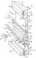
- the single figure shows a perspective view of a section of a surface cladding element according to the invention.
- a surface cladding element 2 consists of a heat transfer profile 4 made of a good heat-conducting material, in particular metal, such as, for example Aluminum.
- a heat transport medium for example water, flows through this pipe 6 and, in the example shown, lies directly or via a heat contact surface which is semicircular in cross section thermal contact layer, not shown.
- the heat contact surface is formed by a receiving groove 8, which is semicircular in its base region and is adapted to the diameter of the pipeline 6, of a partial profile 10 formed in one piece with the heat transfer profile 4. In this case, the pipeline 6 is held in its position shown by holding parts, not shown.
- the heat transfer profile 4 has a laterally open groove 12 and on the opposite long side a matched to the groove 12, extending in the plane of the groove 12 away from this spring 14. Furthermore, the heat transfer profile 4 has in between the groove 12 and the spring 14 lying profile area at least one, preferably integrally formed with the heat transfer profile 4 mounting profile 16, in which fasteners 18 which can be fastened to a wall or ceiling surface (not shown), in particular engage in a form-fitting manner.
- the heat transfer profile 4 is formed with a flat, substantially U-shaped cross-section from a surface wall 20 parallel to the wall or ceiling to be clad and two side walls 22 and 24 approximately perpendicular thereto.
- the groove 12 is preferably formed in that the one side wall 22 into a cross section C-shaped profile section 26 delimiting the groove 12 with two spaced-apart legs 28 and 30 parallel to the surface wall 20 and a web 32 connecting them and perpendicular to the surface wall 20.
- the leg 28 is connected to the side wall 22 in the region of its free end.
- the other side wall 24 merges approximately at right angles into a profile web 34 corresponding to the tongue 14, the thickness of which corresponds approximately to the inside width of the groove 12, ie the inside distance between the legs 28, 30 of the profile section 26.
- the length of the profile web 34 ⁇ measured across the longitudinal axis of the profile is the depth of the groove 12, so that the side walls 24 and 22 can come to rest against each other.
- the profile web 34 measured transversely to the longitudinal axis of the profile, has a greater length than the depth of the groove 12. This results in a distance between the side walls 22 and 24 of two adjacent heat transfer profiles, which leads to the formation of a groove 36 which is delimited by the side walls 22, 24 and the profile web 34 and is open towards the room. Through this groove 36, the effective heat transfer area is advantageously increased. This also results in an attractive appearance.
- the support profile 16 consists of two webs 38 which run parallel in the longitudinal direction of the profile and are arranged approximately perpendicular to the surface wall 20 and which each face one another, parallel to the Surface wall 20 arranged, passing between their free ends including an insertion slot 40 and encompassing the fastening elements 18, pass over retaining webs 42.
- fastening elements 18 can be used, each of which has a, for example plate-shaped, holding part 44 adapted to the cross section enclosed by the webs 38 and the holding webs 42.
- Each of these holding parts 44 preferably has a length which corresponds approximately to the clear distance between the webs 38 of the mounting profile 16, and a width which is ⁇ the width of the insertion slot 40 between the free ends of the holding webs 42.
- the holding parts 44 can either be pushed in the direction of the arrow 46 in the longitudinal direction of the profile into the receiving groove of the support profile 16, or can be guided through the insertion slot 40 from a direction perpendicular to the surface wall 20, ie in the direction of the arrow 48.
- the holding part 44 is subsequently rotated by 90 ° in the direction of the double arrow 50.
- the heat transfer profile 4 has, in particular in the area of the surface wall 20, at least one bead-shaped profile section 52 running in the longitudinal direction of the profile.
- This profile section 52 is formed from two wall webs 54 perpendicular to the surface wall 20 and a wall web 56 connecting them and parallel to the surface wall 20, so that here too an open groove 58 is formed in the direction of the room, through which the effective heat transfer surface advantageously increases.
- the mounting profile 16 described above is arranged in the region of the bead-shaped profile section 52, the webs 38 of the mounting profile 16 being extensions the wall webs 54 of the bead-shaped profile section 52 are formed.
- an attachment bracket 60 provided according to the invention and attachable to the wall or ceiling is also shown in dashed lines.
- This mounting bracket 60 serves to hold the side edge of the outermost room temperature control element and either engages with a leg in the groove 12 or engages with a receiving groove formed in the region of the leg the spring 14 of the respective heat transfer profile 4.
- Only the first one is shown in the drawing Alternative shown.
- a connecting wall 62 or 64 is arranged between the partial profile 10 and on the one hand the side wall 24 and on the other hand the wall web 54 of the bead-shaped profile section 52.
- These connecting walls 62, 64 preferably run parallel to the surface wall 20 at a distance from them and are formed in one piece with the heat transfer profile 4.
- the partial profile 10 and the side wall 24 are spaced relatively far apart.
- it is particularly expedient if, in the central area between the partial profile 10 and the side wall 24, the surface wall 20 is connected to the connecting wall 62 via a web wall 66 arranged perpendicular to the latter.
- a web wall 66 can be arranged analogously to this, as is shown in broken lines.
- the web wall 66 is also formed in one piece with the heat transfer profile 4.
- Both the connecting walls 62, 64 and the web wall (s) 66 preferably extend over the entire length of the heat transfer profile 4, but it is also within the scope of the invention to provide only short portions of these walls 62, 64 and 66 spaced apart from one another by gaps in the longitudinal direction of the profile.
- the heat distribution i.e. the heat gradient within the cladding element 2 according to the invention is significantly improved since, in addition to the surface wall 20, the heat is also distributed or conducted via the connecting walls 62, 64 and, if present, also via the web wall (s) 66.
Landscapes
- Engineering & Computer Science (AREA)
- Physics & Mathematics (AREA)
- Thermal Sciences (AREA)
- Chemical & Material Sciences (AREA)
- Combustion & Propulsion (AREA)
- Mechanical Engineering (AREA)
- General Engineering & Computer Science (AREA)
- Building Environments (AREA)
- Heat-Exchange Devices With Radiators And Conduit Assemblies (AREA)
Claims (12)
- Elément de revêtement de surfaces (2) pouvant être monté, pour couvrir des surfaces, en particulier sur des parois et/ou plafonds, ainsi que pour tempérer des locaux, comportant un profilé de transfert de la chaleur (4) et au moins une conduite tubulaire (6) d'un agent caloporteur s'étendant dans le profilé de transfert de la chaleur (4) et étant en contact de conduction thermique avec celui-ci par une portion profilée (10) réalisée d'une seule pièce, le profilé de transfert de la chaleur (4) présentant sur un côté longitudinal d'une paroi plane (20) parallèle à la paroi ou au plafond, une rainure (12) ouverte latéralement et, sur le côté longitudinal en regard, un ressort (14) adapté à la rainure (12) et s'étendant dans le plan de la rainure (12) vers l'extérieur dans la direction opposée à celle-ci,
caractérisé par le fait que le profilé de transfert de la chaleur (4) comporte deux parois latérales (22, 24) disposées sensiblement perpendiculairement à la paroi plane (20) et ainsi une portion plate sensiblement en forme de U, ainsi que, dans la région de la paroi plane (20), au moins une portion profilée (52) en forme de moulure s'étendant dans la direction longitudinale du profilé, comportant deux parois d'entretoise (54) perpendiculaires à la paroi plane (20), et par le fait qu'entre la portion profilée (10) en contact avec la conduite tubulaire (6) et l'une des parois latérales (22, 24) et/ou entre la portion profilée (10) et l'une des paroi d'entretoise (54) de la portion profilée (52) en forme de moulure s'étend au moins une paroi de liaison (62, 64) sensiblement parallèlement à la paroi plane (20) et à une certaine distance de celle-ci. - Element de revêtement de surfaces selon la revendication 1,
caractérisé par le fait que la ou chaque paroi de liaison (62, 64) s'étend sur toute la longueur du profilé de transfert de la chaleur (4). - Elément de revêtement de surfaces selon la revendication 1 ou 2,
caractérisé par au moins une paroi d'entretoise (66) s'étendant entre la paroi de liaison (62, 64) et la paroi plane (20), sensiblement perpendiculairement à celle-ci et de préférence sur toute la longueur du profilé de transfert de la chaleur (4). - Elément de revêtement de surfaces selon l'une ou plusieurs des revendications 1 à 3,
caractérisé par le fait que le profilé de transfert de la chaleur (4) comporte, dans sa région profilé située entre la rainure (12) et le ressort (14), au moins un profilé de fixation (16) dans lequel s'insèrent par force ou mécaniquement et de manière amovible des éléments de fixation (18) fixés sur la paroi ou au plafond. - Elément de revêtement de surfaces selon l'une ou plusieurs des revendications 1 à 4,
caractérisé par le fait que l'une des parois latérales (22) du profilé de transfert de la chaleur (4) est suivi par une portion profilée (26) qui a une coupe transversale en C, qui délimite la rainure (12) et qui comporte deux branches (28, 30) séparées par une certaine distance et parallèles à la paroi plane (20) et une entretoise (32) qui les relie et qui est perpendiculaire à la paroi plane (20). - Elément de revêtement de surfaces selon l'une ou plusieurs des revendications 1 à 5,
caractérisé par le fait que l'autre paroi latérale (24) du profilé de transfert de la chaleur (4) est suivie, sensiblement à angle droit, d'une entretoise profilée (34) qui forme le ressort (14) et dont l'épaisseur correspond sensiblement à la largeur intérieure de la rainure (12). - Elément de revêtement de surfaces selon la revendication 6,
caractérisé par le fait que la longueur de l'entretoise profilée (34) qui forme le ressort (14), mesurée transversalement à l'axe longitudinal du profilé, est plus grande que la profondeur de la rainure (12). - Elément de revêtement de surfaces selon l'une ou plusieurs des revendications 4 à 7,
caractérisé par la fait que le profilé de fixation (16) consiste en deux entretoises (38) parallèles, disposées sensiblement perpendiculairement à la paroi plane (20) qui sont respectivement suivies par des entretoises de fixation (42) en regard, disposées parallèlement à la paroi plane (20) dont les extrémités libres délimitent une fente d'introduction (40) et qui entourent les éléments de fixation (18). - Eléments de revêtement de surfaces selon l'une ou plusieurs des revendications 4 à 8,
caractérisé par le fait que le profilé de fixation (16) est disposé dans la région de la portion profilée (52) en forme de moulure. - Elément de revêtement de surfaces selon l'une ou plusieurs des revendications 1 à 9,
caractérisé par un équerre de fixation (60) pouvant être fixé sur la paroi ou le plafond, s'engageant dans la rainure (12) ou entourant le ressort (14). - Elément de revêtement de surfaces selon l'une ou plusieurs des revendications 1 à 10,
caractérisé par le fait que, dans la région de la paroi plane (20), la portion profilée (10) qui est en contact de conduction thermique avec la conduite tubulaire (6) est venue d'une pièce avec le profilé de transfert de la chaleur (4). - Elément de revêtement de surfaces selon l'une ou plusieurs des revendications 1 à 11,
caractérisé par le fait que la portion profilée (10) a sensiblement la forme d'un U et comporte une rainure d'accueil (8) de la conduite tubulaire (6), la rainure d'accueil (8) présentant de préférence dans la région de son fond une surface de contact thermique en demi-cercle, adaptée au diamètre de la conduite tubulaire (6).
Priority Applications (1)
| Application Number | Priority Date | Filing Date | Title |
|---|---|---|---|
| AT89118303T ATE103385T1 (de) | 1988-10-21 | 1989-10-03 | Raumtemperierungselement zur montage an wandund deckenflaechen. |
Applications Claiming Priority (4)
| Application Number | Priority Date | Filing Date | Title |
|---|---|---|---|
| DE8813230U | 1988-10-21 | ||
| DE8813230U DE8813230U1 (de) | 1988-10-21 | 1988-10-21 | Raumtemperierungselement zur Montage an Wand- und Deckenflächen |
| DE8815347U DE8815347U1 (de) | 1988-10-21 | 1988-12-10 | Raumtemperierungselement zur Montage an Wand- und Deckenflächen |
| DE8815347U | 1988-12-10 |
Publications (2)
| Publication Number | Publication Date |
|---|---|
| EP0364809A1 EP0364809A1 (fr) | 1990-04-25 |
| EP0364809B1 true EP0364809B1 (fr) | 1994-03-23 |
Family
ID=25953665
Family Applications (1)
| Application Number | Title | Priority Date | Filing Date |
|---|---|---|---|
| EP89118303A Expired - Lifetime EP0364809B1 (fr) | 1988-10-21 | 1989-10-03 | Elément pour tempérer des locaux à monter au mur ou au plafond |
Country Status (2)
| Country | Link |
|---|---|
| EP (1) | EP0364809B1 (fr) |
| DE (2) | DE8815347U1 (fr) |
Families Citing this family (4)
| Publication number | Priority date | Publication date | Assignee | Title |
|---|---|---|---|---|
| GB9322739D0 (en) * | 1993-11-04 | 1993-12-22 | Keymer Michael D | Safety cover |
| US8256690B2 (en) * | 2007-04-27 | 2012-09-04 | Talbott Solar And Radiant Homes, Inc. | Radiant heating and cooling panel |
| DE102017110811A1 (de) * | 2017-05-18 | 2018-11-22 | Dula-Werke Dustmann & Co. Gmbh | Beleuchtbare Verkleidung für Räume und/oder Möbel |
| US20220042305A1 (en) * | 2018-09-16 | 2022-02-10 | Armin Buehler | Profiled section for temperature-control of a room, and building element assembly comprising said profiled section |
Family Cites Families (3)
| Publication number | Priority date | Publication date | Assignee | Title |
|---|---|---|---|---|
| US4424656A (en) * | 1981-06-01 | 1984-01-10 | Airtex Corporation | Assembly clip for ceiling panels |
| GB8401490D0 (en) * | 1984-01-20 | 1984-02-22 | Frenger Troughton Ltd | Ceiling panels |
| SE463977B (sv) * | 1987-09-04 | 1991-02-18 | Ecophon Ab | Undertakskonstruktion |
-
1988
- 1988-12-10 DE DE8815347U patent/DE8815347U1/de not_active Expired
-
1989
- 1989-10-03 DE DE89118303T patent/DE58907284D1/de not_active Expired - Fee Related
- 1989-10-03 EP EP89118303A patent/EP0364809B1/fr not_active Expired - Lifetime
Also Published As
| Publication number | Publication date |
|---|---|
| DE58907284D1 (de) | 1994-04-28 |
| EP0364809A1 (fr) | 1990-04-25 |
| DE8815347U1 (de) | 1989-02-02 |
Similar Documents
| Publication | Publication Date | Title |
|---|---|---|
| EP0364809B1 (fr) | Elément pour tempérer des locaux à monter au mur ou au plafond | |
| DE69409783T2 (de) | Universelle Halterung, insbesondere für die Befestigung einer elektrischen Ausrüstung | |
| DE1559347C3 (fr) | ||
| DE2309664A1 (de) | Befestigungsschelle fuer rohrleitungen | |
| EP0849516A2 (fr) | Elément de montage avec collier de serrage ou élément de fixation similaire | |
| EP0956405B1 (fr) | Ensemble d'un moyen de suspension universel et un rail profile en c | |
| EP0854312A1 (fr) | Dispositif de fixation d'un tuyau | |
| DE102008056423A1 (de) | Halterungselement, Halterungsanordnung und Werkzeug zur Bearbeitung des Halterungselements | |
| DE8813230U1 (de) | Raumtemperierungselement zur Montage an Wand- und Deckenflächen | |
| DE3219464C2 (de) | Befestigungshalterung für nebeneinander verlegbare soleführende Kunststoffrohre | |
| CH658092A5 (de) | Bausatz zum erstellen einer abhaengbaren rasterdecke. | |
| DE19829127C2 (de) | Befestigungselement zum Anbringen U-förmiger Tragprofile an einem Verankerungsgrund | |
| DE8605402U1 (de) | Tragvorrichtung fuer kabelrinnen od. dgl. | |
| DE3827371C2 (de) | Unterkonstruktion für die Befestigung von Paneelen an einer Decke, Wand o. dgl. Fläche eines Bauwerks | |
| DE10034991C1 (de) | Werkzeug zur Betätigung einer auf einem Gewindeschaft eines pilzförmigen Befestigungselementes angeordneten Nutmutter zwecks mechanischer Befestigung bzw. Lösung eines Sitzbeines eines Fluggastsitzes auf einer Sitzschiene | |
| DE2405388C3 (de) | Querprofilschelle für Unterdecken | |
| DE69201518T2 (de) | Biegsames Organ für Kraftübertragung. | |
| EP0670450B1 (fr) | Collier de fixation | |
| DE4029913C2 (fr) | ||
| DE202019104735U1 (de) | Handtuchhalter | |
| DE29811634U1 (de) | Befestigungselement zum Anbringen U-förmiger Tragprofile an einem Verankerungsgrund | |
| EP2017522B1 (fr) | Fixation pour tuyaux | |
| DE2018398C3 (de) | Abstützung mittels einer an einer Stütze befestigten Konsole für Bauteile u.dgl | |
| DE1490844C (fr) | ||
| DE7604400U1 (de) | Aufhaengevorrichtung fuer rohre oder dergleichen |
Legal Events
| Date | Code | Title | Description |
|---|---|---|---|
| PUAI | Public reference made under article 153(3) epc to a published international application that has entered the european phase |
Free format text: ORIGINAL CODE: 0009012 |
|
| AK | Designated contracting states |
Kind code of ref document: A1 Designated state(s): AT CH DE ES FR GB IT LI NL SE |
|
| 17P | Request for examination filed |
Effective date: 19901013 |
|
| 17Q | First examination report despatched |
Effective date: 19910809 |
|
| GRAA | (expected) grant |
Free format text: ORIGINAL CODE: 0009210 |
|
| AK | Designated contracting states |
Kind code of ref document: B1 Designated state(s): AT CH DE ES FR GB IT LI NL SE |
|
| PG25 | Lapsed in a contracting state [announced via postgrant information from national office to epo] |
Ref country code: IT Free format text: LAPSE BECAUSE OF FAILURE TO SUBMIT A TRANSLATION OF THE DESCRIPTION OR TO PAY THE FEE WITHIN THE PRE;WARNING: LAPSES OF ITALIAN PATENTS WITH EFFECTIVE DATE BEFORE 2007 MAY HAVE OCCURRED AT ANY TIME BEFORE 2007. THE CORRECT EFFECTIVE DATE MAY BE DIFFERENT FROM THE ONE RECORDED.SCRIBED TIME-LIMIT Effective date: 19940323 Ref country code: GB Effective date: 19940323 Ref country code: ES Free format text: THE PATENT HAS BEEN ANNULLED BY A DECISION OF A NATIONAL AUTHORITY Effective date: 19940323 Ref country code: SE Free format text: THE PATENT HAS BEEN ANNULLED BY A DECISION OF A NATIONAL AUTHORITY Effective date: 19940323 Ref country code: NL Effective date: 19940323 Ref country code: FR Effective date: 19940323 |
|
| REF | Corresponds to: |
Ref document number: 103385 Country of ref document: AT Date of ref document: 19940415 Kind code of ref document: T |
|
| REF | Corresponds to: |
Ref document number: 58907284 Country of ref document: DE Date of ref document: 19940428 |
|
| EN | Fr: translation not filed | ||
| NLV1 | Nl: lapsed or annulled due to failure to fulfill the requirements of art. 29p and 29m of the patents act | ||
| GBV | Gb: ep patent (uk) treated as always having been void in accordance with gb section 77(7)/1977 [no translation filed] |
Effective date: 19940323 |
|
| PG25 | Lapsed in a contracting state [announced via postgrant information from national office to epo] |
Ref country code: AT Effective date: 19941003 |
|
| PG25 | Lapsed in a contracting state [announced via postgrant information from national office to epo] |
Ref country code: LI Effective date: 19941031 Ref country code: CH Effective date: 19941031 |
|
| PLBE | No opposition filed within time limit |
Free format text: ORIGINAL CODE: 0009261 |
|
| STAA | Information on the status of an ep patent application or granted ep patent |
Free format text: STATUS: NO OPPOSITION FILED WITHIN TIME LIMIT |
|
| 26N | No opposition filed | ||
| REG | Reference to a national code |
Ref country code: CH Ref legal event code: PL |
|
| PGFP | Annual fee paid to national office [announced via postgrant information from national office to epo] |
Ref country code: DE Payment date: 19991220 Year of fee payment: 11 |
|
| PG25 | Lapsed in a contracting state [announced via postgrant information from national office to epo] |
Ref country code: DE Free format text: LAPSE BECAUSE OF NON-PAYMENT OF DUE FEES Effective date: 20010703 |