EP0364901B1 - Reinigungssystem für Bogenoffsetdruckmaschinen - Google Patents
Reinigungssystem für Bogenoffsetdruckmaschinen Download PDFInfo
- Publication number
- EP0364901B1 EP0364901B1 EP89119079A EP89119079A EP0364901B1 EP 0364901 B1 EP0364901 B1 EP 0364901B1 EP 89119079 A EP89119079 A EP 89119079A EP 89119079 A EP89119079 A EP 89119079A EP 0364901 B1 EP0364901 B1 EP 0364901B1
- Authority
- EP
- European Patent Office
- Prior art keywords
- impression cylinder
- cleaning
- blade
- cleaning cloth
- contact
- Prior art date
- Legal status (The legal status is an assumption and is not a legal conclusion. Google has not performed a legal analysis and makes no representation as to the accuracy of the status listed.)
- Expired - Lifetime
Links
- 238000004140 cleaning Methods 0.000 title claims description 252
- 238000007639 printing Methods 0.000 title claims description 29
- 239000004744 fabric Substances 0.000 claims description 122
- 239000007788 liquid Substances 0.000 claims description 38
- 238000003825 pressing Methods 0.000 claims description 37
- 230000007246 mechanism Effects 0.000 claims description 18
- 230000004323 axial length Effects 0.000 claims description 7
- 230000033001 locomotion Effects 0.000 claims description 4
- XLYOFNOQVPJJNP-UHFFFAOYSA-N water Substances O XLYOFNOQVPJJNP-UHFFFAOYSA-N 0.000 description 8
- 230000000694 effects Effects 0.000 description 5
- 239000000463 material Substances 0.000 description 5
- 238000000034 method Methods 0.000 description 4
- 239000002904 solvent Substances 0.000 description 4
- 230000005856 abnormality Effects 0.000 description 3
- 239000007921 spray Substances 0.000 description 3
- 238000012546 transfer Methods 0.000 description 3
- 229910052782 aluminium Inorganic materials 0.000 description 2
- XAGFODPZIPBFFR-UHFFFAOYSA-N aluminium Chemical compound [Al] XAGFODPZIPBFFR-UHFFFAOYSA-N 0.000 description 2
- 238000012423 maintenance Methods 0.000 description 2
- 238000004519 manufacturing process Methods 0.000 description 2
- 238000012544 monitoring process Methods 0.000 description 2
- 230000008439 repair process Effects 0.000 description 2
- 229910001369 Brass Inorganic materials 0.000 description 1
- VYZAMTAEIAYCRO-UHFFFAOYSA-N Chromium Chemical compound [Cr] VYZAMTAEIAYCRO-UHFFFAOYSA-N 0.000 description 1
- 230000009471 action Effects 0.000 description 1
- 239000000853 adhesive Substances 0.000 description 1
- 230000001070 adhesive effect Effects 0.000 description 1
- 239000010951 brass Substances 0.000 description 1
- 229910052804 chromium Inorganic materials 0.000 description 1
- 239000011651 chromium Substances 0.000 description 1
- 239000012459 cleaning agent Substances 0.000 description 1
- 230000002301 combined effect Effects 0.000 description 1
- 230000008602 contraction Effects 0.000 description 1
- 238000001514 detection method Methods 0.000 description 1
- 238000011161 development Methods 0.000 description 1
- 230000018109 developmental process Effects 0.000 description 1
- 238000010586 diagram Methods 0.000 description 1
- 238000001035 drying Methods 0.000 description 1
- 239000000428 dust Substances 0.000 description 1
- 229910052751 metal Inorganic materials 0.000 description 1
- 239000002184 metal Substances 0.000 description 1
- 238000007645 offset printing Methods 0.000 description 1
- 230000003287 optical effect Effects 0.000 description 1
- 239000000843 powder Substances 0.000 description 1
- 230000008569 process Effects 0.000 description 1
- 238000012545 processing Methods 0.000 description 1
- 238000000926 separation method Methods 0.000 description 1
Images


Classifications
-
- B—PERFORMING OPERATIONS; TRANSPORTING
- B41—PRINTING; LINING MACHINES; TYPEWRITERS; STAMPS
- B41F—PRINTING MACHINES OR PRESSES
- B41F35/00—Cleaning arrangements or devices
- B41F35/006—Cleaning arrangements or devices for impression cylinders
-
- B—PERFORMING OPERATIONS; TRANSPORTING
- B41—PRINTING; LINING MACHINES; TYPEWRITERS; STAMPS
- B41P—INDEXING SCHEME RELATING TO PRINTING, LINING MACHINES, TYPEWRITERS, AND TO STAMPS
- B41P2235/00—Cleaning
- B41P2235/10—Cleaning characterised by the methods or devices
- B41P2235/20—Wiping devices
- B41P2235/24—Wiping devices using rolls of cleaning cloth
- B41P2235/242—Unwinding the cleaning cloth
-
- B—PERFORMING OPERATIONS; TRANSPORTING
- B41—PRINTING; LINING MACHINES; TYPEWRITERS; STAMPS
- B41P—INDEXING SCHEME RELATING TO PRINTING, LINING MACHINES, TYPEWRITERS, AND TO STAMPS
- B41P2235/00—Cleaning
- B41P2235/10—Cleaning characterised by the methods or devices
- B41P2235/20—Wiping devices
- B41P2235/24—Wiping devices using rolls of cleaning cloth
- B41P2235/246—Pressing the cleaning cloth against the cylinder
-
- B—PERFORMING OPERATIONS; TRANSPORTING
- B41—PRINTING; LINING MACHINES; TYPEWRITERS; STAMPS
- B41P—INDEXING SCHEME RELATING TO PRINTING, LINING MACHINES, TYPEWRITERS, AND TO STAMPS
- B41P2235/00—Cleaning
- B41P2235/30—Recovering used solvents or residues
- B41P2235/31—Recovering used solvents or residues by filtering
Definitions
- This invention relates to a cleaning system for the impression cylinder of offset sheet-fed printing presses.
- the cleaning cloth 4 fed out from the magazine roll 5 is pressed by this plate in a line against the impression cylinder 1, and the other end of the support plate 7 forms a guide portion 9 provided on the side of the take-up roll 6 to form a configuration whereby the cleaning cloth 4 pressed by the blade 8 to form a line against the impression cylinder 1, is guided and pressed by along arcuate circumferential surface of the impression cylinder 1 so that there is an area of contact in the form of an arcuate circumferential surface, and is then taken-up by the take-up roll 6.
- the cleaning system is provided with an air cylinder as a movement system for the purposes of advancing and retreating the cleaning system to and from the impression cylinder so that the contact with the impression cylinder is prevented when the impression cylinder is rotating at a high speed, and a one-way clutch and air cylinder for progressively moving the cleaning cloth and taking it up. Movement of the blade 8 to move the cleaning cloth 4 with respect to the impression cylinder 1 is performed by a suitable means.
- the numeral 15 indicates a rotating support shaft 15 for bringing the frame 13 into and out of contact with respect to the impression cylinder 1.
- a mechanism that uses the action of a cam or the like to rotate the frame 13 around the center of a rotating support shaft 15 can be provided instead of an escape cam so that the cleaning cloth 4 does not come into contact with the finger 3.
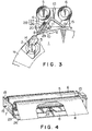
- FIG. 4 is a perspective view of the cleaning system shown in FIG. 3.
- Impression cylinder cleaning system where the blade advances with respect to the impression cylinder
- this embodiment of the present invention in a conventional cleaning system (refer to FIG. 10), has been provided with a pressing mechanism 28 that outwardly urges a blade 8 inside a guide groove 20 of a guide plate 26 that is U-shaped in section, and which is provided on the surface of the inverted-V shaped support plate 7 of the blade 8.
- a guide plate 26 that is U-shaped in section is provided at one end of the inverted-V shaped support plate 7, and houses a blade 8 so as to be movable inside a guide groove 20 by a coil spring 27.
- This blade 8 is arranged so as to uniformly strike the surface of the impression cylinder due to the expansion and contraction of the coil spring 27, and the cleaning cloth 4 is uniformly pressed in a line against the surface of the impression cylinder 1 by the blade 8.
- the guide portion 9 at the other end of the inverted-V shaped support plate 7 is disposed so that the cleaning cloth 4 is brougnt into contact with the arcuate circumferential surface of the surface of the impression cylinder 1.
- the blade 8 and the guide portion 9 can be independently provided to the frame 13 without the use of the inverted-V shaped support plate 7.
- the line-contact blade 36 and the surface pressure pad 37 to simultaneously press the cleaning cloth 4 against the surface of the impression cylinder 1, it is necessary for the surface of the sponge to be soft to that it can form an angle of about 5° to 10°, and for the material to be resistant to both solvents and water (P.P., P.E., PVC, etc.).
- the solvent cleaning, water cleaning drying an other operations can be performed by the impression cylinder cleaning system of the present invention, as a predetermined sequence incorporated into a control device and that is started by an operator pressing the cleaning start button.
Landscapes
- Inking, Control Or Cleaning Of Printing Machines (AREA)
Claims (10)
- Reinigungssystem für Bogenoffsetdruckmaschinen, umfassend:
eine Zubringerwalze (5) zum Ausgeben eines Reinigungstuches (4) zur Durchführung der Reinigung eines Druckzylinders (1),
eine Aufnahmewalze (6) zum Aufnehmen des Reinigungstuches (4),
ein Blatt (36), das zwischen der Zubringerwalze (5) und der Aufnahmewalze (6) vorgesehen ist und sich von der Rückseite des Reinigungstuches (4) in Kontakt mit dem Druckzylinder (1) befindet,
ein Führungselement (33, 34, 35) zum In-Kontakte-Bringen des von dem Blatt (36) niedergepreßten Reinigungstuches mit einer bogenförmigen Umfangsfläche des Druckzylinders und zum In-Kontakt-Bringen entlang der Axiallänge des Druckzylinders, gekennzeichnet durch
zahlreiche Luftzylinder (38) in Richtung der Wellenachse des Druckzylinders, so daß das Blatt und der Führungsteil gegen die Oberfläche des Druckzylinders gepreßt werden, und
einen Rahmen (39) zur Aufnahme des Blattes, der Führung und der Luftzylinder, wobei der Rahmen auf Schienen (41) parallel zu der Oberfläche des Druckzylinders frei bewegbar ist. - Reinigungssystem für Bogenoffsetdruckmaschinen nach Anspruch 1, welches zusätzlich eine Nachweisvorrichtung für den Nachweis einer Position eines Fingers des Druckzylinders umfaßt, wobei Signale von dieser Nachweisvorrichtung zum Antreiben eines Luftzylinders verwendet werden, um das Blatt und die Führung zu dem Druckzylinder vorzuschieben und zurückzuziehen.
- Reinigungssystem für Bogenoffsetdruckmaschinen nach Anspruch 1 oder Anspruch 2, welches zusätzlich eine Vorrichtung zum Aufbringen verschiedener Reinigungsflüssigkeitsarten auf eine Oberfläche des Druckzylinders umfaßt.
- Reinigungssystem für Bogenoffsetdruckmaschinen, umfassend:
eine Zubringerwalze (5) zum Ausgeben eines Reinigungstuches (4) zur Durchführung der Reinigung eines Druckzylinders (1),
eine Aufnahmewalze (6) zum Aufnehmen des Reinigungstuches,
ein Blatt (8), das zwischen der Zubringerwalze und der Aufnahmewalze vorgesehen ist und sich von der Rückseite des Reinigungstuches in Kontakt mit dem Druckzylinder befindet,
ein Führungselement (9) zum In-Kontakt-Bringen des von dem Blatt niedergepreßten Reinigungstuches mit der bogenförmigen Umfangsfläche des Druckzylinders und zum In-Kontakt-Bringen entlang der Axiallänge des Druckzylinders,
ein Reinigungsflüssigkeitszuleitungsrohr (11), das an der Rückseite des Reinigungstuches vorgesehen ist, so daß Reinigungsflüssigkeit zu dem Reinigungstuch geleitet wird, gekennzeichnet durch
ein Druckelement (16), das zwischen dem Blatt und dem Führungsteil vorgesehen ist, so daß der bogenförmige Teil des Reinigungstuches gegen den Zylinder gepreßt wird. - Reinigungssystem für Bogenoffsetdruckmaschinen nach Anspruch 4, wobei das Druckelement stromabwärts angrenzend an das Blatt vorgesehen ist.
- Reinigungssystem für Bogenoffsetdruckmaschinen nach Anspruch 4, wobei das Druckelement an einem stromabwärtigen Ende eines Kontaktbereichs zwischen dem Reinigungstuch und dem Druckzylinder vorgesehen ist.
- Reinigungssystem für Bogenoffsetdruckmaschinen, umfassend:
eine Zubringerwalze (5) zum Ausgeben eines Reinigungstuches (4) zur Durchführung der Reinigung eines Druckzylinders (1),
eine Aufnahmewalze (6) zum Aufnehmen des Reinigungstuches,
ein Blatt (8), das zwischen der Zubringerwalze und der Aufnahmewalze vorgesehen ist und sich von der Rückseite des Reinigungstuches in Kontakt mit dem Druckzylinder befindet,
ein Führungselement (9) zum In-Kontakt-Bringen des von dem Blatt niedergepreßten Reinigungstuches mit der bogenförmigen Umfangsfläche des Druckzylinders und zum In-Kontakt-Bringen entlang der Axiallänge des Druckzylinders,
ein Reinigungsflüssigkeitszuleitungsrohr (11), das an der Rückseite des Reinigungstuches vorgesehen ist, so daß Reinigungsflüssigkeit zu dem Reinigungstuch geleitet wird, dadurch gekennzeichnet, daß
das Blatt (8) derart angeordnet ist, daß es durch einen Druckmechanismus (28) frei in bezug auf den Druckzylinder vorgeschoben und zurückgezogen werden kann. - Reinigungssystem für Bogenoffsetdruckmaschinen nach Anspruch 7, wobei eine Führungsplatte, die eine Führungsrille bildet, an einem Träger befestigt ist, so daß das Blatt innerhalb der Führungsrille frei bewegbar ist und das Blatt durch ein flexibles Element zu der Oberfläche des Druckzylinders vorgeschoben und von dieser zurückgezogen wird.
- Reinigungssystem für Bogenoffsetdruckmaschinen nach Anspruch 8, wobei die Führungsplatte eine lange Rille aufweist, die in die Bewegungsrichtung des Blattes ausgebildet ist, und das Blatt einen Führungsstift aufweist, der für den Eingriff mit der Innenseite der langen Rille montiert ist.
- Reinigungssystem für Bogenoffsetdruckmaschinen nach Anspruch 7, wobei der Druckmechanismus für die Druckausübung von der Rückseite des Reinigungstuches an einem stromabwärtigen Ende eines Kontaktbereichs zwischen dem Reinigungstuch und dem Druckzylinder vorgesehen ist.
Applications Claiming Priority (6)
| Application Number | Priority Date | Filing Date | Title |
|---|---|---|---|
| JP261395/88 | 1988-10-19 | ||
| JP26139588A JP2796721B2 (ja) | 1988-10-19 | 1988-10-19 | オフセット枚葉印刷機圧胴洗浄装置 |
| JP26621/89 | 1989-02-07 | ||
| JP1026621A JP2900265B2 (ja) | 1989-02-07 | 1989-02-07 | 清掃用硬質ブレードの先端あたり精度調整方法 |
| JP1112434A JP2796729B2 (ja) | 1989-05-01 | 1989-05-01 | オフセット枚葉印刷機圧胴洗浄装置 |
| JP112434/89 | 1989-05-01 |
Publications (3)
| Publication Number | Publication Date |
|---|---|
| EP0364901A2 EP0364901A2 (de) | 1990-04-25 |
| EP0364901A3 EP0364901A3 (de) | 1991-02-27 |
| EP0364901B1 true EP0364901B1 (de) | 1994-04-27 |
Family
ID=27285479
Family Applications (1)
| Application Number | Title | Priority Date | Filing Date |
|---|---|---|---|
| EP89119079A Expired - Lifetime EP0364901B1 (de) | 1988-10-19 | 1989-10-13 | Reinigungssystem für Bogenoffsetdruckmaschinen |
Country Status (4)
| Country | Link |
|---|---|
| US (1) | US4991507A (de) |
| EP (1) | EP0364901B1 (de) |
| DD (2) | DD299284A5 (de) |
| DE (1) | DE68914934T2 (de) |
Families Citing this family (19)
| Publication number | Priority date | Publication date | Assignee | Title |
|---|---|---|---|---|
| CA2024054A1 (en) * | 1989-09-01 | 1991-03-02 | Yoshichika Murakami | Cleaner for rotary bodies such as blanket cylinder, impression cylinder, ink supply rollers and the like |
| JP2900272B2 (ja) * | 1989-12-27 | 1999-06-02 | 大日本印刷株式会社 | オフセット枚葉印刷機圧胴洗浄装置 |
| JP2564517Y2 (ja) * | 1991-05-24 | 1998-03-09 | 株式会社小森コーポレーション | 輪転印刷機のインキ洗浄装置 |
| US5450792A (en) * | 1992-10-02 | 1995-09-19 | Baldwin Graphic Systems, Inc. | Automatic cleaning system for press rollers and cylinders |
| DE4233953A1 (de) * | 1992-10-08 | 1994-04-14 | Baldwin Gegenheimer Gmbh | Druckmaschinenzylinder-Waschvorrichtung |
| US5323217A (en) * | 1993-03-22 | 1994-06-21 | Moore Business Forms, Inc. | Ion deposition printer cleaning apparatus and related method |
| DE4319258C2 (de) * | 1993-06-09 | 2003-10-09 | Heidelberger Druckmasch Ag | Reinigungsvorrichtung für Druckmaschinen |
| JP3006820B2 (ja) * | 1994-06-08 | 2000-02-07 | 清水製作株式会社 | 印刷機のドラム洗浄装置 |
| DE19506640C2 (de) * | 1995-02-25 | 1998-09-10 | Roland Man Druckmasch | Einrichtung zum Reinigen von Zylindern in Druckmaschinen |
| DE19527249C2 (de) * | 1995-07-26 | 1999-11-11 | Grafotec Gmbh | Vorrichtung zum Reinigen von Arbeitsflächen einer Druckmaschine |
| JP3604785B2 (ja) * | 1995-07-26 | 2004-12-22 | 株式会社小森コーポレーション | 印刷機のシリンダ洗浄装置 |
| DE19611125C2 (de) * | 1996-03-21 | 1999-09-02 | Heidelberger Druckmasch Ag | Reinigungseinrichtung an Rotationsdruckmaschinen |
| DE69714119T2 (de) * | 1996-04-09 | 2003-03-27 | Baldwin-Japan Ltd., Tokio/Tokyo | Zylinderreinigungsvorrichtung und Vorrichtung zur Ablage des Reinigungstuches |
| US5918544A (en) * | 1996-04-16 | 1999-07-06 | Mpm Corporation | Cleaner for printing devices having means to disengage web from fluid source |
| JP3023421B2 (ja) * | 1997-02-19 | 2000-03-21 | 日本ボールドウィン株式会社 | シリンダ洗浄装置および洗浄方法 |
| DE10000549A1 (de) * | 2000-01-08 | 2001-07-12 | Baldwin Grafotec Gmbh | Waschbalken für Druckmaschinenzylinder |
| CN101870197B (zh) | 2009-04-23 | 2014-06-04 | 海德堡印刷机械股份公司 | 洗涤装置 |
| US9302465B2 (en) * | 2013-09-28 | 2016-04-05 | Xds Holdings Inc. | Apparatus, assembly and method for dry cleaning a flexographic printing plate carried on a plate cylinder that includes optimized cleaning functionalities |
| CN111647413B (zh) * | 2020-06-23 | 2023-07-14 | 大连华锐重工焦炉车辆设备有限公司 | 一种焦炉机械通用的淌焦刀清扫装置及其使用方法 |
Family Cites Families (5)
| Publication number | Priority date | Publication date | Assignee | Title |
|---|---|---|---|---|
| CA476011A (en) * | 1951-08-14 | Addressograph-Multigraph Corporation | Apparatus for cleaning printing surfaces in offset printing machines | |
| CA227927A (en) * | 1923-01-16 | ?Rthur Edmund Brown | Compressed air jack | |
| US4638733A (en) * | 1984-01-20 | 1987-01-27 | Horst Rebhan | Squeegee head for printing of bodies by the screen printing method |
| JPS61857A (ja) * | 1984-06-14 | 1986-01-06 | Meidensha Electric Mfg Co Ltd | 平面及び立体的に環状なシステム結合方式 |
| DE3789975T2 (de) * | 1986-08-02 | 1994-09-08 | Dainippon Printing Co Ltd | Reinigungssystem für eine Druckmaschine. |
-
1989
- 1989-10-13 EP EP89119079A patent/EP0364901B1/de not_active Expired - Lifetime
- 1989-10-13 DE DE68914934T patent/DE68914934T2/de not_active Expired - Fee Related
- 1989-10-17 DD DD89333651A patent/DD299284A5/de unknown
- 1989-10-17 DD DD34442589A patent/DD302015A7/de not_active IP Right Cessation
- 1989-10-19 US US07/424,179 patent/US4991507A/en not_active Expired - Lifetime
Also Published As
| Publication number | Publication date |
|---|---|
| US4991507A (en) | 1991-02-12 |
| EP0364901A2 (de) | 1990-04-25 |
| DD299284A5 (de) | 1992-04-09 |
| DE68914934D1 (de) | 1994-06-01 |
| EP0364901A3 (de) | 1991-02-27 |
| DD302015A7 (de) | 1994-11-03 |
| DE68914934T2 (de) | 1994-10-13 |
Similar Documents
| Publication | Publication Date | Title |
|---|---|---|
| EP0364901B1 (de) | Reinigungssystem für Bogenoffsetdruckmaschinen | |
| US4986182A (en) | Cleaning apparatus and cleaning method of blanket of printing press | |
| US5150650A (en) | Cleaner for rotary bodies such as blanket cylinder, impression cylinder, ink supply rollers and the like | |
| US5117754A (en) | Cleaning apparatus for impression cylinder of offset sheet-fed press | |
| US4781116A (en) | Washing method and apparatus for guide rollers of rotary press | |
| US4555989A (en) | Apparatus for washing a rubber blanket cylinder of a printing machine | |
| US4982469A (en) | Apparatus for cleaning surface of sheet | |
| JP3604785B2 (ja) | 印刷機のシリンダ洗浄装置 | |
| JP2001270087A (ja) | 印刷機の胴、特に版胴及びゴム胴用の消去兼クリーニング装置 | |
| US3952654A (en) | Automatic blanket wash-up system | |
| US5438923A (en) | Method and apparatus for the prevention of aerosol deposits in a rotary printing press | |
| US5537924A (en) | Shifting of washing device within its housing | |
| CA2481457C (en) | Erasing and cleaning apparatus for cylinders, in particular printing form and blanket cylinders of a printing press | |
| US3693547A (en) | Cleaning unit for printing press blanket | |
| EP0224930B1 (de) | Druckvorrichtung für Pastillen | |
| US5887524A (en) | Washing device in the printing unit of rotary printing presses | |
| IL36853A (en) | Apparatus and method for cleaning rotating cylindrical surfaces | |
| JP2796729B2 (ja) | オフセット枚葉印刷機圧胴洗浄装置 | |
| JPH02182459A (ja) | 印刷機 | |
| EP0423093B1 (de) | Verfahren und Anordnung zum Reinigen von Führungsrollen | |
| JPH10329299A (ja) | 印刷機 | |
| JPH07115468B2 (ja) | 円筒体外周面の洗浄装置 | |
| US6272988B1 (en) | Device for cleaning bearer surfaces on rotating cylinders | |
| US10065410B2 (en) | Apparatus for cleaning surfaces | |
| JPS63268649A (ja) | 輪転印刷機のガイドロ−ラ拭浄方法 |
Legal Events
| Date | Code | Title | Description |
|---|---|---|---|
| PUAI | Public reference made under article 153(3) epc to a published international application that has entered the european phase |
Free format text: ORIGINAL CODE: 0009012 |
|
| AK | Designated contracting states |
Kind code of ref document: A2 Designated state(s): CH DE FR GB IT LI SE |
|
| PUAL | Search report despatched |
Free format text: ORIGINAL CODE: 0009013 |
|
| AK | Designated contracting states |
Kind code of ref document: A3 Designated state(s): CH DE FR GB IT LI SE |
|
| 17P | Request for examination filed |
Effective date: 19910809 |
|
| 17Q | First examination report despatched |
Effective date: 19930726 |
|
| GRAA | (expected) grant |
Free format text: ORIGINAL CODE: 0009210 |
|
| AK | Designated contracting states |
Kind code of ref document: B1 Designated state(s): CH DE FR GB IT LI SE |
|
| REF | Corresponds to: |
Ref document number: 68914934 Country of ref document: DE Date of ref document: 19940601 |
|
| ITF | It: translation for a ep patent filed | ||
| ET | Fr: translation filed | ||
| ITTA | It: last paid annual fee | ||
| EAL | Se: european patent in force in sweden |
Ref document number: 89119079.5 |
|
| PLBE | No opposition filed within time limit |
Free format text: ORIGINAL CODE: 0009261 |
|
| STAA | Information on the status of an ep patent application or granted ep patent |
Free format text: STATUS: NO OPPOSITION FILED WITHIN TIME LIMIT |
|
| 26N | No opposition filed | ||
| REG | Reference to a national code |
Ref country code: GB Ref legal event code: IF02 |
|
| REG | Reference to a national code |
Ref country code: CH Ref legal event code: PFA Owner name: DAI NIPPON INSATSU KABUSHIKI KAISHA Free format text: DAI NIPPON INSATSU KABUSHIKI KAISHA#1-1, KAGA-CHO 1-CHOME ICHIGAYA#SHINJUKU-KU/TOKYO (JP) -TRANSFER TO- DAI NIPPON INSATSU KABUSHIKI KAISHA#1-1, KAGA-CHO 1-CHOME ICHIGAYA#SHINJUKU-KU/TOKYO (JP) |
|
| PGFP | Annual fee paid to national office [announced via postgrant information from national office to epo] |
Ref country code: SE Payment date: 20070921 Year of fee payment: 19 |
|
| PGFP | Annual fee paid to national office [announced via postgrant information from national office to epo] |
Ref country code: IT Payment date: 20071030 Year of fee payment: 19 Ref country code: CH Payment date: 20071003 Year of fee payment: 19 |
|
| PGFP | Annual fee paid to national office [announced via postgrant information from national office to epo] |
Ref country code: FR Payment date: 20071026 Year of fee payment: 19 Ref country code: GB Payment date: 20071031 Year of fee payment: 19 |
|
| PGFP | Annual fee paid to national office [announced via postgrant information from national office to epo] |
Ref country code: DE Payment date: 20071206 Year of fee payment: 19 |
|
| REG | Reference to a national code |
Ref country code: CH Ref legal event code: PL |
|
| EUG | Se: european patent has lapsed | ||
| GBPC | Gb: european patent ceased through non-payment of renewal fee |
Effective date: 20081013 |
|
| REG | Reference to a national code |
Ref country code: FR Ref legal event code: ST Effective date: 20090630 |
|
| PG25 | Lapsed in a contracting state [announced via postgrant information from national office to epo] |
Ref country code: IT Free format text: LAPSE BECAUSE OF NON-PAYMENT OF DUE FEES Effective date: 20081013 Ref country code: DE Free format text: LAPSE BECAUSE OF NON-PAYMENT OF DUE FEES Effective date: 20090501 |
|
| PG25 | Lapsed in a contracting state [announced via postgrant information from national office to epo] |
Ref country code: CH Free format text: LAPSE BECAUSE OF NON-PAYMENT OF DUE FEES Effective date: 20081031 Ref country code: LI Free format text: LAPSE BECAUSE OF NON-PAYMENT OF DUE FEES Effective date: 20081031 Ref country code: FR Free format text: LAPSE BECAUSE OF NON-PAYMENT OF DUE FEES Effective date: 20081031 |
|
| PG25 | Lapsed in a contracting state [announced via postgrant information from national office to epo] |
Ref country code: GB Free format text: LAPSE BECAUSE OF NON-PAYMENT OF DUE FEES Effective date: 20081013 |
|
| PG25 | Lapsed in a contracting state [announced via postgrant information from national office to epo] |
Ref country code: SE Free format text: LAPSE BECAUSE OF NON-PAYMENT OF DUE FEES Effective date: 20081014 |