EP0364988A2 - Procédé pour revêtir des plaques métalliques - Google Patents
Procédé pour revêtir des plaques métalliques Download PDFInfo
- Publication number
- EP0364988A2 EP0364988A2 EP89119350A EP89119350A EP0364988A2 EP 0364988 A2 EP0364988 A2 EP 0364988A2 EP 89119350 A EP89119350 A EP 89119350A EP 89119350 A EP89119350 A EP 89119350A EP 0364988 A2 EP0364988 A2 EP 0364988A2
- Authority
- EP
- European Patent Office
- Prior art keywords
- metal
- plating
- plating metal
- nozzle
- molten
- Prior art date
- Legal status (The legal status is an assumption and is not a legal conclusion. Google has not performed a legal analysis and makes no representation as to the accuracy of the status listed.)
- Withdrawn
Links
Images




Classifications
-
- C—CHEMISTRY; METALLURGY
- C23—COATING METALLIC MATERIAL; COATING MATERIAL WITH METALLIC MATERIAL; CHEMICAL SURFACE TREATMENT; DIFFUSION TREATMENT OF METALLIC MATERIAL; COATING BY VACUUM EVAPORATION, BY SPUTTERING, BY ION IMPLANTATION OR BY CHEMICAL VAPOUR DEPOSITION, IN GENERAL; INHIBITING CORROSION OF METALLIC MATERIAL OR INCRUSTATION IN GENERAL
- C23C—COATING METALLIC MATERIAL; COATING MATERIAL WITH METALLIC MATERIAL; SURFACE TREATMENT OF METALLIC MATERIAL BY DIFFUSION INTO THE SURFACE, BY CHEMICAL CONVERSION OR SUBSTITUTION; COATING BY VACUUM EVAPORATION, BY SPUTTERING, BY ION IMPLANTATION OR BY CHEMICAL VAPOUR DEPOSITION, IN GENERAL
- C23C6/00—Coating by casting molten material on the substrate
-
- C—CHEMISTRY; METALLURGY
- C23—COATING METALLIC MATERIAL; COATING MATERIAL WITH METALLIC MATERIAL; CHEMICAL SURFACE TREATMENT; DIFFUSION TREATMENT OF METALLIC MATERIAL; COATING BY VACUUM EVAPORATION, BY SPUTTERING, BY ION IMPLANTATION OR BY CHEMICAL VAPOUR DEPOSITION, IN GENERAL; INHIBITING CORROSION OF METALLIC MATERIAL OR INCRUSTATION IN GENERAL
- C23C—COATING METALLIC MATERIAL; COATING MATERIAL WITH METALLIC MATERIAL; SURFACE TREATMENT OF METALLIC MATERIAL BY DIFFUSION INTO THE SURFACE, BY CHEMICAL CONVERSION OR SUBSTITUTION; COATING BY VACUUM EVAPORATION, BY SPUTTERING, BY ION IMPLANTATION OR BY CHEMICAL VAPOUR DEPOSITION, IN GENERAL
- C23C26/00—Coating not provided for in groups C23C2/00 - C23C24/00
- C23C26/02—Coating not provided for in groups C23C2/00 - C23C24/00 applying molten material to the substrate
-
- C—CHEMISTRY; METALLURGY
- C23—COATING METALLIC MATERIAL; COATING MATERIAL WITH METALLIC MATERIAL; CHEMICAL SURFACE TREATMENT; DIFFUSION TREATMENT OF METALLIC MATERIAL; COATING BY VACUUM EVAPORATION, BY SPUTTERING, BY ION IMPLANTATION OR BY CHEMICAL VAPOUR DEPOSITION, IN GENERAL; INHIBITING CORROSION OF METALLIC MATERIAL OR INCRUSTATION IN GENERAL
- C23C—COATING METALLIC MATERIAL; COATING MATERIAL WITH METALLIC MATERIAL; SURFACE TREATMENT OF METALLIC MATERIAL BY DIFFUSION INTO THE SURFACE, BY CHEMICAL CONVERSION OR SUBSTITUTION; COATING BY VACUUM EVAPORATION, BY SPUTTERING, BY ION IMPLANTATION OR BY CHEMICAL VAPOUR DEPOSITION, IN GENERAL
- C23C2/00—Hot-dipping or immersion processes for applying the coating material in the molten state without affecting the shape; Apparatus therefor
- C23C2/04—Hot-dipping or immersion processes for applying the coating material in the molten state without affecting the shape; Apparatus therefor characterised by the coating material
Definitions
- the present invention relates to a method of continuously plating metal sheets on surfaces without employing a molten metal bath.
- a widely known method of forming a plating film on a steel strip surface may include a hot dip method of immersing a steel strip into a molten plating metal.
- a steel strip is carried out with a thermal treatment in a pre-heating furnace and a surface cleansing treatment, subsequently immersed into a molten zinc bath so as to form a plating film thereon, drawn out of the bath, adjusted in an amount of plating adhesion by squeezing gases, and performed with a surface treatment by means of a galvannel or the like.
- molten metal plated steel sheets have more beauty and are excellent in an anti-corrosive property, and hence such steel sheets are widely used.
- This method makes use of a technique of coating a paint having a high viscosity.
- the method feeds the molten metal from the tank to the nozzle, in which an amount of plating adhesion is controlled in accordance with head pressure of the molten metal tank.
- variations in bath level within the tank appear as scattering in amount of plating adhesion. This makes bad accuracy relative to the amount of plating adhesion.
- a molten metal tank similar to the dipping plating bath is required, so that the above mentioned various problems appear.
- the present invention provides a plating method of metal sheets by use of a plating metal supplying device having an upward nozzle, comprising the steps of passing upwards a metal sheet to be plated in close proximity to one side edge of an upwardly-directed nozzle; successively melting a solidus plating metal from the top end of or just before a port of the nozzle by a heat melting means while successively feeding the solidus plat ing metal toward the nozzle port within the device; discharging the molten plating metal from the nozzle port so as to form a pool of the molten plating metal at a corner defined by a metal plate surface and a tip of the nozzle; adhering the plating metal of the metal pool to the surface of the passing metal sheet, thereby forming a plating film thereon.
- the greatest feature of the invention is that the solidus plating metal is molten by an amount of estimated plating just before plating, and the thus molten material is plated. This manner extremely facilitates handling of the plating metal and also controls the amount of adhesion in comparison with the above mentioned method in Japanese Patent Specification Laid-Open No. 61-207555.
- Another feature of the invention is not that the molten plating metal is supplied directly to the metal sheet surface but that the metal pool is temporarily formed at the corner between the nozzle tip and the metal sheet by the balance between a surface expansion and a pressure, and the plating is formed while the plating metal of the pool is upheaved by an upwardly passing metal sheet.
- the metal supplying amount (onto the metal sheet surface) from the nozzle is determined depending upon a clearance formed between the nozzle tip and the sheet surface. It is therefore required that the clearance be extremely small to be substantially equivalent to the thickness of the plating film.
- the metal sheet is, however, inevitably somewhat vibrated during passing, and it is not easy to maintain constant the fine clearance in relation with the nozzle due to the bad shapes of the sheet, and this causes non-uniformity in the plating thickness and troubles due to impingement of the nozzle upon the sheet.
- the metal supplying amount does not depend upon the clearance between the nozzle and the sheet surface, thereby obtaining a uniform thickness with stability, irrespective of the above mentioned clearance.
- the clearance may be diminished within a range enough to form a metal pool. As a result, it is possible to provide a wide clearance enough to prevent the impingement of the nozzle upon the sheet.
- the features of the above mentioned methods (ii) to (v) are present in that a high temperature gas is blown on the plating metal fed from the nozzle in the direction of the metal sheet from the side of the nozzle.
- a melting condition of the plating metal becomes uniform crosswise, and the molten plating metal can be supplied in the width of the metal sheet at a constant velocity of flow. Namely, uneveness in melting the plating metal is more or less inevitable. If the molten plating metal is made to flow naturally towards the steel sheet without blowing the high temperature gas as in the invention, the melting condition becomes non-uniform, and the velocity of metal flow is not thereby constant.
- the plating is formed with uneveness in the length (in the direction of the sheet line), which in turn brings about non-uniformity in amount of adhesion.
- the metal melting is made uniform crosswise by a gas blow and is controlled at a constant velocity of flow whereby uniform plating can be performed.
- the high temperature gas acts to melt the plating metal in addition to the above mentioned functions.
- the plating metal can be molten more uniformly than ever before particularly in the system of melting the plating metal with the high temperature gas alone.
- the feature of the method (vi) lies in that a gas staying under the liquid metal pool is sucked and exhausted outside, thereby properly preventing the gas from invading into the plating film.
- the feature of the method (vii) lies in that a rotary body is contacted with the underside of the steel strip of a plating treatment unit, and a plating process can thereby be practised by preventing the vibrations of the metal plate.
- Figs.1 and 2 illustrate embodiments in which a plating method is applied to a continuously plating process of a steel strip.
- the reference numeral 1 designates a plating metal supplying device; 2 is a plating metal; and 3 is a steel strip to be plated.
- the plating metal supplying device 1 includes a guide member 4 for guiding upwards the metal material 2 of a solidus condition (sheet shape in this embodiment).
- the guide member 4 has an upwardly-directed discharge nozzle 5 at its top end (upper end) for discharging the molten plating metal.
- the guide member 4 is composed of a cylindrical body oblong in section in this embodiment.
- the top end of the guide member 4 is provided with a heat melting means comprising a heating member 6 (a heater or the like) for melting a plating metal.
- the plating metal supplying device 1 has a feed mechanism (not illustrated) comprising a feed roller or a cylinder unit for feeding the solidus plating metal 2 to the discharging nozzle.
- the steel strip 3 passes upwards in close proximity to one side edge 51 of the upwardly-directed discharge nozzle 5 with respect to the plating metal supply device 1.
- the solidus plating metal 2 is successively fed towards the discharge nozzle within the supply device 1. Subsequently, the materials 2 are molten in due order from the top ends thereof just before a port of the discharge nozzle, and discharged from the discharge nozzle 5.
- the discharged molten plating metal (A) forms a pool of a liquid metal 8 at a corner 7 defined by a tip of the discharge nozzle and a surface of the steel strip.
- the molten plating metal (A) of the pool 8 is adhered so as to be upheaved by the steel strip 3 moving upwardly, thus forming a plating film 9.
- a gap between the side edge 51 of the discharge nozzle and the steel strip 3 is to be narrowed down to the strip so that the molten metal (A) of the pool 8 does not drop down from the gap. If the gap is excessively small, however, the nozzle will impinge upon the steel strip. For this reason, a gap (W) is set preferivelyably within a range of 0.5 - 5 mm.
- Fig.3 illustrates an example where the discharge nozzle 5 is inclined, while the angle ⁇ of the corner 7 is diminished.
- the direction in which the steel strip 3 passes is not necessarily vertical.
- the steel strip 3 can pass obliquely upwards within such a range adequately forming the molten metal pool 8.
- Inner diameters of the guide member 4 and of the discharge nozzle 5 are not necessarily equal to each other.
- the nozzle may be formed smaller in diameter than the guide member 4 as shown in Fig.4.
- Fig.5 illustrates one example where the plating method of the invention is applied to production of a multi-layered plating steel plate.
- a plurality of guide members 4a - 4c to which plating metals 2a - 2c are fed, and these plating metals are molten and discharged from discharge nozzles 5a - 5c, respectively.
- the pools are formed in that the plating metals A1 - A3 are layered.
- Laminated plating films of the plating metals or plating metal components are distributed obliquely in the thickness, whereby so-called oblique component plating films are obtained.
- Some structural devices are, as the cases may be, made by providing, for example, a weir plate on the way to the metal pool 8. It is possible to acquire plating films having uniform components where three kinds of components are mixed substantially uniformly.
- Figs.6 to 16 show various kinds of embodiments of the invention.
- Figs.6 and 7 show the embodiments where a high temperature gas is blown from the side of the nozzle 5.
- a gas supply port 10 is formed in a position opposite to the side on which a steel strip passes, with the discharge nozzle interposed therebetween, facing to a nozzle port from which a molten plating metal (A) is discharged and undergoes a blow of a high temperature gas in the direction of the steel strip.
- the slit width of the supply port 10 is set generally to 2 - 50 mm.
- a gas having a temperature higher than the melting point of the plating metal is blown from a gas supply port 10 on the molten plating metal (A).
- the molten plating metal (A) With blow of the high temperature gas, the molten plating metal (A) is forcibly carried away towards the steel strip 3 at a constant velocity of flow without being solidified, thus forming a metal pool 8 at a corner 7 defined by the tip of the discharge nozzle and the steel strip surface.
- the molten plating metal (A) of the pool 8 is adhered so as to be upheaved by the upwardly moving steel strip 3, thus forming a palting film 9.
- the steel strip 3 and the nozzle tip define the corner 7, an angle ⁇ of which can be properly selected.
- the discharge nozzle 5 is inclined, while the angle ⁇ of the corner 7 can be decreased.
- a direction of blowing of the high temperature gas from the gas supply port 10 is not limited to the one parallel with a face of the nozzle port. If a large angle to the nozzle port face is made in the blowing direction, large splushes are caused in the molten plating metal. This causes deterioration in surface condition of the plating film.
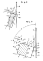
- Figs.8 and 9 show that the high temperature gas for controlling a velocity of flow of the molten palting metal, while Fig.6 shows that the plating metal 2 is molten just before the nozzle port by the heat melting means.
- a plating metal supply device 1′ includes a supply nozzle 5′ for supplying the plating metal as it remains solidus at a top end of the guide member 4.
- the top end of the guide member 4 is mounted with a preheat mechanism, composed of a heating body 6 (a heater or the like), for preheating the plating metal.
- a ags supply port facing to a nozzle port from which the plating metal is supplied and undergoes a blow of a high temperature gas in the direction of the steel strip.
- the steel strip 3 passes upwards in close proximity to one side edge 51 of the upwardly-directed supply nozzle 5′ with respect to the plating metal supply device 1′.
- the solidus plating metal is successively fed towards the supply nozzle port within the supply device 1′ and preheated by the preheat mechanism. Therefore, the plating metal 2 is supplied from a port of the supply nozzle 5′.
- the gas having a temperature higher than the melting point of the plating metal is blown on the plating metal 2 from the gas supply port 10.
- the gas for use generally has a temperature higher than the melting point by a range of 50 to 150 °C but lower than the boiling point of the plating metal.
- the plating metal is, e.g., Zn
- normally a gas of 500°C or above is employed.
- the plating metal is molten by this high temperature gas, and a resultant molten metal (A) is forced to be carried away toward the steel strip 3 at a constant velocity of flow by undergoing a further gas blow, thus forming the liquid metal pool 8 at the corner 7 defined by the discharge nozzle tip and the steel strip surface.
- the molten plating metal (A) of the liquid metal pool 8 is adhered so as to be upheaved by the upwardly moving steel strip 3, thus forming the plating film 9.
- the high temperature gas is blown both for melting of the plating metal and for controlling the velocity of flow of the molten plating metal.
- a hot dip zinc plating is carried out on the steel strip by the above mentioned method under, for example, the following conditions. Thickness of Zn-plate (plating metal): 5 mm Preheat temperature of Zn-plate: 410°C Temperature of gas: 550°C Flow velocity of gas: 5 m/s Slit width of gas supply port: 5 mm
- a heat melting device 11 is disposed outside of and opposite to a supply nozzle 5′, by which the placing metal 2 fed from the supply nozzle 5′ is molten.
- a high temperature gas is, as seen in Fig.6, blown on the molten plating metal (A), and then carried away towards the steel strip.
- the melting of the plating metal 2 may be performed by heating of the heat melting device 11 in combination with the high temperature gas.
- a structure relative to this case is the same as that shown in Figs.10 and 11.
- Figs.12 and 13 show the embodiments which suck and exhaust the gas staying under the molten metal pool.
- the plating metal supply device 1 includes a degassing passageway 12 formed, at its one end, with an opening 120 to a lower part of a side edge 51 of the discharge nozzle. A gas staying under a plating treatment unit is sucked and exhausted by a sucking device (not shown).
- the gas is drawn away from a space (S) below the liquid metal pool 8 via the degassing passageway 12.
- the air bubbles are involved into the plating film by a static pressure within the space (S) increasing due to a concomitant gas flow with the steel strip 3.
- the pressure is reduced by removing the gas to prevent from involving into the plating film.
- the pressure in the space (S) is preferably kept substantially constant, generally around a pressure equivalent to the atmospheric pressure plus the pressure of the height h of the pool.
- Figs.14 and 15 show the embodiments where the rear side of the steel strip is contactd with a rotary body (roll body).
- a side edge 51 of the discharge nozzle 5 is disposed in opposite to a side of the roll member 13.
- the steel strip 3 passes while being coiled on the roll member 13. Then, the steel strip 3 passes upwards such that its underside touches the roll member 10 in close proximity to the side edge 51 of the discharge nozzle.
- the molten plating metal (A) discharged from the nozzle forms a liquid metal pool 8 at a corner 7 defined by a tip of the discharge nozzle and a surface of the steel strip.
- the molten plating metal (A) of the pool 8 is so adhered as to be upheaved by the upwardly moving steel strip 3, thus forming a plating film 9.
- Fig.16 shows an example where an endless belt 13′ is used as a rotary body.
- One side of the steel strip 3 is brought into contact with an upwardly-directed travelling surface of the endless belt 13′, and the steel strip 3 passes in synchronism therewith.
- the liquid metal pool 8 is forced between the nozzle tip and the other side of the steel strip 3 whose one side is in contact with the belt. Then, plating is formed on the sheet surface.
- the plating process can be performed in arbitrary positions of the rotary body and is not limited to those shown in the respective embodiments given above.
- a direction in which the steel strip is pulled out of the rotary body after practising the plating process can be arbitrarily selected.
- the steel strip 3 may undergo the plating process at a normal temperature. In this case, however, non-uniform thermal expansion takes place in the sheet due to a sharp increase in the sheet temperature when being in contact with the molten metal, and the sheet will be deformed unpreferably. Prevention of this may be effected by preheating the steel strip 3 at a predetermined temperature (preferably, around the melting point of the plating metal) and practising a plating process on this steel strip.
- a slight scatter in amount of adhesion is somewhat caused due to vibrations of the steel strip.
- a uniform treatment is carried out by a surface treatment device.
- the surface treatment device as an ultrasonic vibrating type (so-called ultrasonic trowel) including, e.g., an ultrasonic vibrator, may be used.
- the surface treatment device is retained by a cylinder unit having a buffer mechanism, and a vibrating sheet thereof is forced to lightly touch the steel strip surface on which a plating film is formed.
- the ultrasonic vibrations are imparted to the plating film, whereby the film thickness of the plating metal can be uniform.
- Figs.14 and 16 show examples where a surface treatment device 14 of such an ultrasonic vibrator is provided, and the number 15 designates the vibrating plate.
- the plating treatment based on the method of the invention is carried out preferably in a non-oxidizing atmosphere (e.g., a mixed gas of H2 of 20 - 25% and N2 of 80 - 75%) in order to secure plating wetness and adhesion as well.
- a non-oxidizing atmosphere e.g., a mixed gas of H2 of 20 - 25% and N2 of 80 - 75%) in order to secure plating wetness and adhesion as well.
- the steel strip surfce is cleansed as much as possible before plating is executed also in the inventive method.
- the plating method of the invention can be applied to platings of various kinds of metals and alloy metals.
- the steel strip can be subjected to, for instance, Zn plating, Al-Zn alloy plating, Co-Cr-Zn alloy plating (e.g., l%Co-l%Cr-Zn alloy plating), Al-Mg-Zn alloy plating (e.g., 5%Al-0.6%Mg-Zn alloy plating), Al-Si-Zn alloy plating, (e.g., 55%Al-1.6%Si-Zn alloy plating), Si-Al alloy plating (e.g., 10%Si-Al alloy plating) and Sn-Pb alloy plating (e.g., 10%Sn-Pb alloy plating).
- Zn plating Al-Zn alloy plating
- Co-Cr-Zn alloy plating e.g., l%Co-l%Cr-Zn alloy plating
- the metal material 2 is supplied to only one side of the steel strip 3.
- the devices 1, 1′ and the rotary member are disposed on both sides of the steel strip to perform plating on each surface thereof. In this case, plating on both surfaces is not necessarily formed in the same position in the line direction.
- plating metals 2 each having a different composition are set on both sides of the steel strip, and double-side heterogeneous plating can be thereby performed with facility.
- an external plate of a house electric appliance or the like it is possible to acquire a steel strip having one side (a coating surface) formed with an Fe-Zn alloy plating film and the other side (a naked surface) formed with a Zn plating film.
- the plating metal 2 assuming a sheet shape is employed. Instead, for example a powdery plating metal may be used. In this case, the plating metal 2 is likewise charged in the guide member 4 and fed by a proper feeding means in the direction of the nozzle.
- a surface heating device 16 as shown may be disposed to prevent a drop in temperature of the steel strip.
- the plating films of the molten metal can be formed consecutively on the metal sheet without employing any molten metal bath.
- the plating method of the invention exhibits the following advantages as compared with the conventional methods using the plating metal bath.
- the plating metal can be handled in an extremely easy manner, and the amount of plating adhesion can be controlled on the basis of a velocity at which the solidus plating metal is fed, thereby attaining a high accuracy associated with the adhesion quantity by virtue of a system of feeding the solidus plating metal, melting only an estimated amount of plating metal just before the nozzle and adhering the molten plating metal to the metal sheet.
- the system of the invention is based not on that the molten plating metal is supplied directly to the metal sheet surface but on that the molten plating metal discharged from the nozzle is temporarily stagnated in the metal pool formed at the corner defined by the nozzle and the metal sheet, and the plating metal of the pool is so adhered as to be upheaved by the upwardly passing metal sheet.
- the plating film having a constant thickness can be obtained regardless of a gap between the sheet surface and the nozzle. It is not required that the gap between the nozzle and the metal sheet is made minute in terms of a plating thickness order. Hence, even when some vibrations and deterioration in configuration are caused in the metal sheet, impingement upon the nozzle can be prevented to the greatest possible degree.
- the underside of the steel strip of the plating treatment unit is brought into contact with the rotary body, and it is therefore possible to carry out the plating process while preventing flaps of the steel strip. In consequence, the distribution of the amount of plating adhesion appears uniform, and collision of the nozzle against the sheet is also prevented. It is possible to manufacture a molten plating steel sheet with the uniform amount of adhesion and no defect on the surface.
Landscapes
- Chemical & Material Sciences (AREA)
- Chemical Kinetics & Catalysis (AREA)
- Engineering & Computer Science (AREA)
- Materials Engineering (AREA)
- Mechanical Engineering (AREA)
- Metallurgy (AREA)
- Organic Chemistry (AREA)
- Coating With Molten Metal (AREA)
Applications Claiming Priority (8)
| Application Number | Priority Date | Filing Date | Title |
|---|---|---|---|
| JP63261639A JPH02111855A (ja) | 1988-10-19 | 1988-10-19 | 金属板の溶融めっき方法 |
| JP261639/88 | 1988-10-19 | ||
| JP63261641A JPH02111857A (ja) | 1988-10-19 | 1988-10-19 | 溶融めつき金属板の製造方法 |
| JP261641/88 | 1988-10-19 | ||
| JP262947/88 | 1988-10-20 | ||
| JP63262947A JPH02111858A (ja) | 1988-10-20 | 1988-10-20 | 金属板の溶融めつき方法 |
| JP63264086A JPH02111861A (ja) | 1988-10-21 | 1988-10-21 | 金属板の溶融めっき方法 |
| JP264086/88 | 1988-10-21 |
Publications (2)
| Publication Number | Publication Date |
|---|---|
| EP0364988A2 true EP0364988A2 (fr) | 1990-04-25 |
| EP0364988A3 EP0364988A3 (fr) | 1991-07-10 |
Family
ID=27478589
Family Applications (1)
| Application Number | Title | Priority Date | Filing Date |
|---|---|---|---|
| EP19890119350 Withdrawn EP0364988A3 (fr) | 1988-10-19 | 1989-10-18 | Procédé pour revêtir des plaques métalliques |
Country Status (4)
| Country | Link |
|---|---|
| US (1) | US4973500A (fr) |
| EP (1) | EP0364988A3 (fr) |
| KR (1) | KR930003029B1 (fr) |
| CA (1) | CA2000941A1 (fr) |
Families Citing this family (4)
| Publication number | Priority date | Publication date | Assignee | Title |
|---|---|---|---|---|
| TW199911B (fr) * | 1991-12-04 | 1993-02-11 | Armco Steel Co Lp | |
| US5339329A (en) * | 1993-01-25 | 1994-08-16 | Armco Steel Company, L.P. | Induction heated meniscus coating vessel |
| JP5669610B2 (ja) * | 2011-02-15 | 2015-02-12 | 株式会社アステア | 直接通電加熱方法 |
| KR20160029151A (ko) | 2011-05-27 | 2016-03-14 | 에이케이 스틸 프로퍼티즈 인코포레이티드 | 메니스커스 코팅 장치 및 방법 |
Family Cites Families (11)
| Publication number | Priority date | Publication date | Assignee | Title |
|---|---|---|---|---|
| US1496309A (en) * | 1921-12-31 | 1924-06-03 | Harvey F Girvin | Process and apparatus for coating metal articles |
| US3081535A (en) * | 1958-08-26 | 1963-03-19 | Sylvania Electric Prod | Flux application |
| US3066041A (en) * | 1959-07-29 | 1962-11-27 | Stahl & Walzwerke Rasselstein | Method of hot-dip metallising metal strips |
| US3062181A (en) * | 1960-09-02 | 1962-11-06 | Eastman Kodak Co | Apparatus for applying magnetic sound track |
| US3916043A (en) * | 1971-11-15 | 1975-10-28 | Eastman Kodak Co | Method of coating a spliced web |
| US3776297A (en) * | 1972-03-16 | 1973-12-04 | Battelle Development Corp | Method for producing continuous lengths of metal matrix fiber reinforced composites |
| FR2299893A1 (fr) * | 1975-02-07 | 1976-09-03 | Labo Electronique Physique | Procede de fabrication en continu de silicium |
| US4283443A (en) * | 1977-01-27 | 1981-08-11 | Polaroid Corporation | Method and apparatus for coating webs |
| CH648601A5 (fr) * | 1979-07-31 | 1985-03-29 | Battelle Memorial Institute | Procede de revetement en continu d'un substrat metallique sur une partie au moins de sa surface par un autre metal et dispositif pour la mise en oeuvre de ce procede. |
| US4445458A (en) * | 1982-07-21 | 1984-05-01 | E. I. Du Pont De Nemours And Company | Beveled edge metered bead extrusion coating apparatus |
| US4566624A (en) * | 1983-12-16 | 1986-01-28 | Hollis Automation, Inc. | Mass wave soldering system |
-
1989
- 1989-10-13 US US07/421,517 patent/US4973500A/en not_active Expired - Fee Related
- 1989-10-17 KR KR1019890014924A patent/KR930003029B1/ko not_active Expired - Lifetime
- 1989-10-18 EP EP19890119350 patent/EP0364988A3/fr not_active Withdrawn
- 1989-10-18 CA CA002000941A patent/CA2000941A1/fr not_active Abandoned
Also Published As
| Publication number | Publication date |
|---|---|
| KR930003029B1 (ko) | 1993-04-16 |
| KR900006553A (ko) | 1990-05-08 |
| EP0364988A3 (fr) | 1991-07-10 |
| CA2000941A1 (fr) | 1990-04-19 |
| US4973500A (en) | 1990-11-27 |
Similar Documents
| Publication | Publication Date | Title |
|---|---|---|
| GB2041009A (en) | Coating one side only of steel strip with molten coating metal | |
| US4973500A (en) | Method of plating metal sheets by passing the sheet upwards in close proximity to an upwardly directed nozzle | |
| EP0245862A1 (fr) | Procédé pour revêtir d'un film liquide des matériaux à base de fer | |
| US5073415A (en) | Apparatus for coating an iron based metal with a liquid protective metal and method | |
| JP2650248B2 (ja) | 鋼板の連続金属めっき装置 | |
| EP0450069A1 (fr) | Procede de placage en continu de plaques metalliques | |
| JPH07113154A (ja) | 溶融金属めっき方法及び装置 | |
| JPH05311388A (ja) | 金属板の連続溶融金属めっき方法及びその装置 | |
| JPH02111858A (ja) | 金属板の溶融めつき方法 | |
| JPH02111855A (ja) | 金属板の溶融めっき方法 | |
| JPH10226864A (ja) | 溶融亜鉛めっき鋼板の製造方法 | |
| JPH02111859A (ja) | 溶融めつき金属板の製造方法 | |
| JPH02298246A (ja) | 金属ストリップの連続溶融めっき方法 | |
| JPH02111861A (ja) | 金属板の溶融めっき方法 | |
| JP2850539B2 (ja) | 高圧溶融金属供給装置 | |
| JPH02111860A (ja) | 溶融めつき金属板の製造方法 | |
| JPH02111857A (ja) | 溶融めつき金属板の製造方法 | |
| JP3508538B2 (ja) | 溶融金属めっき鋼板の製造装置 | |
| JP2981412B2 (ja) | 溶融金属めっき鋼板の製造方法及び製造装置 | |
| JPH02111864A (ja) | 溶融めつき金属板の製造方法 | |
| JPS63109148A (ja) | 溶融金属メツキ方法 | |
| CA2028295A1 (fr) | Methode de metallisation continue de feuilles de tole | |
| JPH02111856A (ja) | 溶融めつき金属板の製造方法 | |
| JPH01272772A (ja) | 金属板の連続めっき方法 | |
| JP2001200353A (ja) | 溶融金属めっき鋼板の製造方法 |
Legal Events
| Date | Code | Title | Description |
|---|---|---|---|
| PUAI | Public reference made under article 153(3) epc to a published international application that has entered the european phase |
Free format text: ORIGINAL CODE: 0009012 |
|
| AK | Designated contracting states |
Kind code of ref document: A2 Designated state(s): DE FR GB |
|
| 17P | Request for examination filed |
Effective date: 19900514 |
|
| PUAL | Search report despatched |
Free format text: ORIGINAL CODE: 0009013 |
|
| AK | Designated contracting states |
Kind code of ref document: A3 Designated state(s): DE FR GB |
|
| 17Q | First examination report despatched |
Effective date: 19920922 |
|
| STAA | Information on the status of an ep patent application or granted ep patent |
Free format text: STATUS: THE APPLICATION IS DEEMED TO BE WITHDRAWN |
|
| 18D | Application deemed to be withdrawn |
Effective date: 19930203 |