EP0365146A2 - Sperrvorrichtung - Google Patents
Sperrvorrichtung Download PDFInfo
- Publication number
- EP0365146A2 EP0365146A2 EP89309557A EP89309557A EP0365146A2 EP 0365146 A2 EP0365146 A2 EP 0365146A2 EP 89309557 A EP89309557 A EP 89309557A EP 89309557 A EP89309557 A EP 89309557A EP 0365146 A2 EP0365146 A2 EP 0365146A2
- Authority
- EP
- European Patent Office
- Prior art keywords
- locking member
- solenoid valve
- receptacle
- valve assembly
- blocking
- Prior art date
- Legal status (The legal status is an assumption and is not a legal conclusion. Google has not performed a legal analysis and makes no representation as to the accuracy of the status listed.)
- Granted
Links
Images


Classifications
-
- F—MECHANICAL ENGINEERING; LIGHTING; HEATING; WEAPONS; BLASTING
- F16—ENGINEERING ELEMENTS AND UNITS; GENERAL MEASURES FOR PRODUCING AND MAINTAINING EFFECTIVE FUNCTIONING OF MACHINES OR INSTALLATIONS; THERMAL INSULATION IN GENERAL
- F16L—PIPES; JOINTS OR FITTINGS FOR PIPES; SUPPORTS FOR PIPES, CABLES OR PROTECTIVE TUBING; MEANS FOR THERMAL INSULATION IN GENERAL
- F16L37/00—Couplings of the quick-acting type
- F16L37/008—Couplings of the quick-acting type for branching pipes; for joining pipes to walls
-
- F—MECHANICAL ENGINEERING; LIGHTING; HEATING; WEAPONS; BLASTING
- F16—ENGINEERING ELEMENTS AND UNITS; GENERAL MEASURES FOR PRODUCING AND MAINTAINING EFFECTIVE FUNCTIONING OF MACHINES OR INSTALLATIONS; THERMAL INSULATION IN GENERAL
- F16H—GEARING
- F16H61/00—Control functions within control units of change-speed- or reversing-gearings for conveying rotary motion ; Control of exclusively fluid gearing, friction gearing, gearings with endless flexible members or other particular types of gearing
- F16H61/0003—Arrangement or mounting of elements of the control apparatus, e.g. valve assemblies or snapfittings of valves; Arrangements of the control unit on or in the transmission gearbox
- F16H61/0009—Hydraulic control units for transmission control, e.g. assembly of valve plates or valve units
-
- F—MECHANICAL ENGINEERING; LIGHTING; HEATING; WEAPONS; BLASTING
- F16—ENGINEERING ELEMENTS AND UNITS; GENERAL MEASURES FOR PRODUCING AND MAINTAINING EFFECTIVE FUNCTIONING OF MACHINES OR INSTALLATIONS; THERMAL INSULATION IN GENERAL
- F16H—GEARING
- F16H61/00—Control functions within control units of change-speed- or reversing-gearings for conveying rotary motion ; Control of exclusively fluid gearing, friction gearing, gearings with endless flexible members or other particular types of gearing
- F16H61/02—Control functions within control units of change-speed- or reversing-gearings for conveying rotary motion ; Control of exclusively fluid gearing, friction gearing, gearings with endless flexible members or other particular types of gearing characterised by the signals used
- F16H61/0202—Control functions within control units of change-speed- or reversing-gearings for conveying rotary motion ; Control of exclusively fluid gearing, friction gearing, gearings with endless flexible members or other particular types of gearing characterised by the signals used the signals being electric
- F16H61/0251—Elements specially adapted for electric control units, e.g. valves for converting electrical signals to fluid signals
-
- Y—GENERAL TAGGING OF NEW TECHNOLOGICAL DEVELOPMENTS; GENERAL TAGGING OF CROSS-SECTIONAL TECHNOLOGIES SPANNING OVER SEVERAL SECTIONS OF THE IPC; TECHNICAL SUBJECTS COVERED BY FORMER USPC CROSS-REFERENCE ART COLLECTIONS [XRACs] AND DIGESTS
- Y10—TECHNICAL SUBJECTS COVERED BY FORMER USPC
- Y10T—TECHNICAL SUBJECTS COVERED BY FORMER US CLASSIFICATION
- Y10T137/00—Fluid handling
- Y10T137/6851—With casing, support, protector or static constructional installations
-
- Y—GENERAL TAGGING OF NEW TECHNOLOGICAL DEVELOPMENTS; GENERAL TAGGING OF CROSS-SECTIONAL TECHNOLOGIES SPANNING OVER SEVERAL SECTIONS OF THE IPC; TECHNICAL SUBJECTS COVERED BY FORMER USPC CROSS-REFERENCE ART COLLECTIONS [XRACs] AND DIGESTS
- Y10—TECHNICAL SUBJECTS COVERED BY FORMER USPC
- Y10T—TECHNICAL SUBJECTS COVERED BY FORMER US CLASSIFICATION
- Y10T74/00—Machine element or mechanism
- Y10T74/21—Elements
- Y10T74/2186—Gear casings
Definitions
- the present invention relates generally to locking mechanisms for demountably attaching one article to another. More particularly, the present invention relates to a secure locking mechanism that can demountably attach one article to another without the use of screws or other similarly essential, but separate, mounting means as specified in the preamble of claim 1, for example as disclosed in US-A-2,077,584. Specifically, the present invention relates to a locking mechanism that is particularly adapted for demountably securing a solenoid valve assembly to the housing of an electronically-controlled automotive transmission.
- the solenoid valve assemblies have been secured to the transmission housing by a plurality of individual fastening means.
- the transmission housing may include a separate control housing to which the solenoids are secured.
- the solenoid valve assemblies have been secured by snap-rings, machine screws, or the like.
- Such mounting devices either secure a mounting flange presented from the solenoid frame to the transmission housing or secure a separate cap member which performs the functions of enclosing the solenoid to protect it from potentially deleterious exposure to the environment while simultaneously capturing and securing it in operative position on the transmission housing.
- a locking mechanism for demountably securing a solenoid valve assembly within a receptacle in the wall of a transmission housing according to the present invention is characterised by the features specified in the characterising portion of claim 1.
- a locking mechanism embodying the concepts of the present invention is adapted demountably to secure a solenoid valve assembly within a receptacle in the wall of a transmission housing.
- a retention means is relatively permanently secured to the solenoid valve assembly, and a stop means is presented from the retention means.
- a first blocking face is presented from the transmission housing to be engaged by the stop means and thereby to limit the angular range through which the solenoid valve assembly may be rotated within the receptacle.
- the retention means also presents an engaging surface, and a second blocking face is presented from the transmission housing.
- the engaging surface is disposed in opposition to the second blocking face in order to preclude withdrawal of the solenoid valve assembly from the receptacle when the stop means engages the first blocking face.
- a latching means is presented from the retention means, and a third blocking face is presented from the transmission housing. Engagement, or opposition, of the latching means with the third blocking face normally precludes retro-rotation of the solenoid valve assembly within the receptacle when the stop means engages the first blocking face.
- a biasing means permits selective displacement of at least the latching means out of operative engagement with all blocking surfaces: (1) to permit that rotation of the solenoid valve assembly within the receptacle which transports the engaging surface presented from the retention means into opposition with the second blocking face in order to preclude withdrawal of the solenoid valve assembly from the receptacle, and conversely (2) to permit retro-rotation of the retention means within the receptacle which transports the engaging surface out of opposition with the second blocking surface in order to permit withdrawal of the solenoid valve assembly from the receptacle.
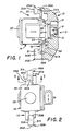
- FIG. 10 One representative form of a locking mechanism embodying the concepts of the present invention is depicted in Figures 1-4 of the accompanying drawings and is designated generally by the numeral 10 thereon.
- the locking mechanism 10 may be adapted for use in other environments, the locking mechanism 10 has particular suitability for demountably securing solenoid valve assemblies to the walls of electrically-controlled transmission housings.
- a wall 11 of a transmission housing 12 is provided with a stepped receptacle 13 adapted operatively to receive a solenoid valve assembly 14.
- the stepped receptacle 13 presents a central aperture 15 within which a valve mechanism -- indicated generally by the numeral 16, and forming a part of the solenoid valve assembly 14 -- is operatively received.
- the details of the valve mechanism 16 and its co-operative interaction with the various passages within the wall 11, a typical example of which is designated at 18, form no part of the present invention and are, in fact, so well-known to the art that they are not described herein.
- a recess 20 concentrically circumscribes the central aperture 15 to receive a neck portion 21 on a valve housing 22 of the solenoid assembly 14.
- Solenoid 23 itself is secured to the valve housing 22 by means well-known to the art and will not, therefore, be described herein.
- One or more pillars 25 are presented from the transmission housing 11, and the pillars 25 comprise a principal portion of the locking mechanism.
- a particular structural member, component or arrangement may be employed at more than one location.
- a common numerical designation shall be employed.
- one of the structural members, components or arrangements so identified is to be individually identified, or referenced, it shall be designated by virtue of a letter suffix employed in combination with the numerical designation employed for general identification of that structural member, component or arrangement.
- each pillar 25 has a pedestal portion 26 which is integrally formed with, and extends outwardly from, the wall 11 of the transmission housing 12 to terminate in an integral head portion 30 that is disposed in spaced relation outwardly from the wall 11 of the transmission housing 12.
- the head portions 30A and 30B of the respective pillars 25A and 25B preferably extend toward each other from their respective supporting pedestal portions 26A and 26B.
- Each head portion 30 presents three blocking faces.
- the first blocking face 31 comprises one lateral wall of the head portion 30.
- the second blocking face 32 on each head portion 30 comprises the obverse wall thereof, and as such the second blocking face 32 opposingly faces the wall 11 of the transmission housing 12.
- the third blocking face 33 also comprises one lateral wall of the head portion 30.
- the third blocking face 33 is thus laterally spaced with respect to the first blocking face 31, and the first and third blocking faces 31 and 33, respectively, are thus disposed substantially perpendicularly with respect to the second blocking face 32.
- a retention means 35 which also comprises a principal portion of the locking mechanism 10, is preferably secured within the solenoid valve assembly 14 in a relatively permanent manner.
- the retention means 35 comprises a plate-like locating member 36 and a separate latching member 38.
- the locating member 36 has a hub portion 39 which is notched, as at 40, to permit assembly within the solenoid valve assembly 14.
- the notch 40 can be replaced with a simple aperture. Bores 41 which penetrate the hub portion 39 of the locating member 36 are used to assure accurate radial location within the solenoid valve assembly 14.
- diametrically-opposed arms 42A and 42B on the locating member 36 extend radially outwards relative to the solenoid frame 22 to present engaging surfaces 43A and 43B in proximity to the radially outer extremity of each arm 42A and 42B, respectively.
- the engaging surfaces 43A and 43B can, by selective rotation of the solenoid valve assembly 14 with the locating member 36 secured thereto, be selectively disposed in opposing juxtaposition with respect to the corresponding second blocking faces 32A and 32B on the head portions 30A and 30B of the pillar means 25A and 25B, respectively.
- a stop lug 45 extends perpendicularly outwardly from one lateral edge of each engaging surface 43A and 43B on the locating member 36. Engagement of the stop lug 45A with the first blocking face 31A on the head portion 30A of pillar means 25A simultaneously with engagement of the stop lug 45B with the first blocking face 31B on the head portion 30B of pillar means 25B determines the extent to which the locating member 36 can be rotated, in one direction, when the solenoid valve assembly 14 is received within the receptacle 13.
- the stop lugs 45A and 45B are located on the diagonally opposite edges of the engaging surfaces 43A and 43B, respectively, and when disposed as depicted the lugs 45 determine the extent to which the solenoid valve assembly 14 can be rotated (in a clockwise direction as viewed).
- the latching member 38 is likewise disposed transversely relatively to the valve housing 22, and the latching member 38 is also preferably secured within the solenoid valve assembly 14 in a relatively permanent manner.
- the latching member 38 as best depicted in Figure 4, has a hub portion 46 which has a suitable aperture 48 therein to accommodate assembly. Bores 49 which penetrate the hub portion 46 of the latching member 38 are used to assure accurate radial location within the solenoid valve assembly 14.
- diametrically-opposed fingers 50A and 50B on the latching member 38 extend radially outwards relative to the valve housing 22.
- Each finger 50 comprises a cantilevered spring which terminates in a latching dog 55 which extends perpendicularly outwards from the radially outermost extremity of each finger 50 selectively, and operably, to interact with the third blocking face 33 on the head portion 30 of each pillar 25 to prevent retro-rotation of the solenoid assembly 14 when the latching dog 55 has operably engaged the third blocking face 33.
- the latching dogs 55 In order to effect automatic locking and to facilitate unlocking, the latching dogs 55 must be capable of being displaced out of operative engagement with each blocking face 32, 32 and 33 on the head portion 30 of the appropriate pillar 25.
- the biasing action of at least one spring finger 50 not only urges the latching dog 55 carried thereon into operative, locking interaction with the third blocking face 33 on the head portion 30 of the appropriate pillar but also permits the required selective displacement of the latching dog 55 necessary to move the latching dog 55 out of operative engagement with the first and third blocking faces 31 and 33, respectively, on the head portion 30 of each such pillar 25.
- a camming ramp 56 is incorporated as the leading edge on each latching dog 55.
- the camming ramps 56 are disposed so that rotation (clockwise as viewed in Figure 2) of the solenoid frame 22 drives the camming ramp 56 against a striker edge 58 which defines the intersection between the first and second blocking faces 31 and 32, respectively, on the head portion 30 of each pillar 25.
- a striker edge 58 which defines the intersection between the first and second blocking faces 31 and 32, respectively, on the head portion 30 of each pillar 25.
- the biasing action of the fingers 50A and 50B urges the latching dogs 55A and 55B to move so that blocking surfaces incorporated as trailing edges 60A and 60B on the latching dogs 55A and 55B opposingly interact with the respective third blocking faces 33A and 33B.
- the trailing edge 60A of the latching dog 55A is angularly inclined. Were both the trailing edges 60 disposed perpendicularly with respect to the fingers 50, the trailing edges 60 would engage the third blocking face 33 on each pillar 25 to preclude retro-rotation of the solenoid valve assembly 14.
- trailing edges 60 when the trailing edges 60 are each inclined, as depicted by the trailing edge 60A in Figure 3, they will each engage the third blocking face 33 at its intersection with the second blocking face 32. As such, the inclination of the trailing edge 60 must be such that it cannot serve as a cam. This is imperative inasmuch as the purpose of the latching dog 55 is to preclude retro-rotation of the solenoid valve assembly 14 when the latching dog 55 operatively interacts with any part of the third blocking face 33, including just that portion of the third blocking face 33 which intersects the second blocking face 32 and to maintain contact between stop lugs 45 and blocking faces 31.
- one of the trailing edges; i.e., 60A can be disposed perpendicular with respect to the fingers 50 and thereby provide a positive retention structure.
- each latching dog 55 is capable of being selectively displaced operatively to disengage from the appropriate third blocking face 33.
- each latching dog 55 By mounting each latching dog 55 on the outboard end of cantilevered spring finger 50 one may selectively displace the latching dogs 55 out of operative interaction with the third blocking faces 33 so that the solenoid valve assembly 14 may be retro-rotated.
- locking mechanism 110 an alternative embodiment of the locking mechanism of the invention, shown as locking mechanism 110, is depicted.
- a wall 111 of a transmission housing 112 is provided with a stepped receptacle 113 adapted operatively to receive a solenoid valve assembly 114.
- the stepped receptacle 113 presents a central aperture 115 within which a valve mechanism -- indicated generally by the numeral 116, and forming a part of the solenoid valve assembly 114 -- is operatively received.
- valve mechanism 116 As with the first embodiment described herein, the details of the valve mechanism 116 and its co-operative interaction with the interior of the transmission housing 112 as well as with various passages (not shown) situated within the wall 111 form no part of the present invention and, in fact, are so well-known to the art that they are not described herein.
- a recess 120 concentrically circumscribes the central aperture 115 to receive a neck portion 121 on valve housing 122 of the solenoid assembly 114.
- the solenoid 123 itself is secured within the housing 122 by means well-known to the art and will not, therefore, be described herein.
- one or more pillars 125 are presented from the wall 111 of the transmission housing 112, and the pillars 125 also comprise a principal portion of the locking mechanism 110.
- pillars 125A and 125B are disposed in diametric opposition to one another relative to the receptacle 113.
- Each pillar 125A and 125B has a pedestal portion 126 which extends outwardly from the wall 111 of the transmission housing 112 to terminate in a head portion 130 that is disposed in spaced relation outwardly from the wall 111 of the transmission housing 112.
- the head portions 130A and 130B of the respective pillars 125A and 125B preferably extend towards each other from their respective supporting pedestal portions 126A and 126B.
- Each head portion 130 presents three blocking faces.
- the first blocking face 131 comprises one lateral wall of the head portion 130.
- the second blocking face 132 on each head portion 130 comprises the obverse wall thereof, and as such the second blocking face 132 opposingly faces the wall 111 of the transmission housing 112.
- the third blocking face 133 also comprises one lateral wall of the head portion 130.
- the third blocking face 133 is thus laterally spaced with respect to the first blocking face 131 and the first and third blocking faces 131 and 133, respectively, are thus disposed substantially perpendicularly with respect to the second blocking face 132.
- the retention means 135 comprises a single locking member 137 and a spring 157.
- the locking member 137 has a hub portion 139 which is provided with a suitable opening (not shown) to permit assembly within the solenoid valve assembly 114.
- diametrically-opposed arms 142A and 142B on the locking member 137 extend radially outwards relative to the valve housing 122 to present engaging surfaces 143A and 143B in proximity to the radially outer extremity of each arm 142A and 142B, respectively.
- the engaging surfaces 143A and 143B can, by selective rotation of the solenoid valve assembly 114 with the locking member 137 secured thereto, be selectively disposed in opposing juxtaposition with respect to the second blocking faces 132A and 132B on the head portions 130A and 130B of the respective pillar means 125A and 125B.
- Stop lugs 145A and 145B extend perpendicularly outwardly from one lateral edge of the respective engaging surfaces 143A and 143B on the locking member 137 to engage the first blocking faces 131A and 131B on the head portion 130 of each pillar means 125A and 125B and thereby determine the extent to which the solenoid valve assembly 114 can be rotated, in one direction.
- the stop lugs 145A and 145B are located on the diagonally opposite edges of the engaging surfaces 143A and 143B, respectively, and when disposed as depicted the lugs 145 determine the extent which the solenoid assembly 114 can be rotated in a clockwise direction.
- Latching dogs 155A and 155B extend perpendicularly outwards from the opposite lateral edges of the respective engaging surfaces 143A and 143B on locking member 137.
- the latching dogs 155 are located in laterally-spaced relation with respect to the stop lugs 145 and thus on the opposite side of the engaging surfaces 143.
- Each latching dog 155 is adapted, and located, selectively to engage the third blocking face 133 on the head portion 130 of each pillar 125 to prevent retro-rotation of the solenoid assembly 114 when the latching dog 155 is disposed in opposition to the third blocking face 133.
- the latching dogs 155 In order to effect selective locking and unlocking of the locking mechanism 110, the latching dogs 155 must be permitted to be displaced against the biasing action of the spring 157 to allow the latching dogs 155 to pass unrestricted past the pillar means 125.
- the spring 157 is received within a space 158 which circumscribes the recess 120 and is interposed between the locking member 137 and a surface 159 of the space 158 biasingly to urge the solenoid valve assembly 114 axially outwards of the receptacle 113.
- the opposed juxtaposition of the engaging surfaces 143 with the second blocking face 132 on the head portion 130 of each pillar 125 secures the solenoid valve assembly 114 within the receptacle 113.
- the latching dogs 155 be capable of being selectively displaced operatively to clear the first blocking face 131 on each pillar 125 and permit the solenoid valve assembly 114 to be rotated until the stop lug 145 engages the first blocking face 131.
- the latching dogs 155 be capable of being selectively displaced operatively to disengage from the third blocking face 33 so the solenoid valve assembly 114 may be retro-rotated sufficiently for the engaging surfaces 143 and the latching dogs 155 to clear the pillars 125.
- the entire solenoid valve assembly 114 may be displaced axially inwardly a sufficient distance to displace the latching lugs 155 out of operative engagement with the head portion 130 of each pillar 125 so that the solenoid valve assembly 14 may be rotated to secure it in operative position in the receptacle or retro-rotated to effect withdrawal thereof.
- a locking mechanism embodying the concepts of the present invention not only provides a novel and unique means which can be readily and easily employed demountably to secure a solenoid valve assembly to the housing of a transmission but also accomplishes the other objects of the invention.
Landscapes
- Engineering & Computer Science (AREA)
- General Engineering & Computer Science (AREA)
- Mechanical Engineering (AREA)
- Magnetically Actuated Valves (AREA)
- Connection Of Plates (AREA)
- General Details Of Gearings (AREA)
- Preventing Unauthorised Actuation Of Valves (AREA)
Applications Claiming Priority (2)
| Application Number | Priority Date | Filing Date | Title |
|---|---|---|---|
| US07/258,951 US4842010A (en) | 1988-10-18 | 1988-10-18 | Locking mechanism |
| US258951 | 1988-10-18 |
Publications (3)
| Publication Number | Publication Date |
|---|---|
| EP0365146A2 true EP0365146A2 (de) | 1990-04-25 |
| EP0365146A3 EP0365146A3 (de) | 1992-12-09 |
| EP0365146B1 EP0365146B1 (de) | 1994-07-06 |
Family
ID=22982822
Family Applications (1)
| Application Number | Title | Priority Date | Filing Date |
|---|---|---|---|
| EP89309557A Expired - Lifetime EP0365146B1 (de) | 1988-10-18 | 1989-09-20 | Sperrvorrichtung |
Country Status (4)
| Country | Link |
|---|---|
| US (1) | US4842010A (de) |
| EP (1) | EP0365146B1 (de) |
| JP (1) | JP2703072B2 (de) |
| DE (1) | DE68916611T2 (de) |
Cited By (5)
| Publication number | Priority date | Publication date | Assignee | Title |
|---|---|---|---|---|
| WO2001007810A1 (de) * | 1999-07-23 | 2001-02-01 | Zf Friedrichshafen Ag | Proportionalventil |
| EP1052490A3 (de) * | 1999-05-12 | 2001-09-05 | Siemens Canada limited | Schnappbefestigungsvorrichtung |
| EP1284380A3 (de) * | 2001-08-17 | 2003-07-02 | Eaton Corporation | Verfahren und Vorrichtung zum Montieren von Elektromagnetventilen |
| EP1508734A1 (de) * | 2003-08-19 | 2005-02-23 | MAC Valves, Inc. | Elektromagnetisch betätigtes Pneumatikventil mit einem integrierten Durchgang und einem schnellen Einfassungskörper |
| CN109424762A (zh) * | 2017-08-31 | 2019-03-05 | 株式会社开滋Sct | 促动器用电磁阀的安装构造和带有促动器的阀门 |
Families Citing this family (20)
| Publication number | Priority date | Publication date | Assignee | Title |
|---|---|---|---|---|
| US4960153A (en) * | 1989-11-03 | 1990-10-02 | G. T. Products, Inc. | Fuel tank vapor vent valve |
| US5083583A (en) * | 1990-09-04 | 1992-01-28 | G.T. Products, Inc. | Fuel tank vapor vent valve and seal |
| DE4201570C2 (de) * | 1992-01-22 | 1995-04-13 | Danfoss As | Stellvorrichtung |
| US5449227A (en) * | 1994-07-08 | 1995-09-12 | Ford Motor Company | Solenoid attachment for antilock brake system |
| US6085615A (en) * | 1997-02-12 | 2000-07-11 | Rostra Precision Controls, Inc. | Bracket for solenoids on vehicle transmissions |
| JP3553307B2 (ja) * | 1997-02-17 | 2004-08-11 | ジヤトコ株式会社 | 自動変速機のコントロールバルブ装置 |
| US6230585B1 (en) | 1998-03-27 | 2001-05-15 | Rostra Precision Controls, Inc. | Slip over bracket for transmission solenoids |
| JP3749026B2 (ja) * | 1998-11-27 | 2006-02-22 | 三菱電機株式会社 | ソレノイドバルブの固定装置 |
| US6050384A (en) * | 1998-12-18 | 2000-04-18 | Hammond; Edmund | Method and apparatus for rapid transmission brake release |
| US6766991B1 (en) | 2002-05-10 | 2004-07-27 | Derek Nance | Dry sump pump bracket |
| US6955337B2 (en) * | 2003-04-03 | 2005-10-18 | Delphi Technologies, Inc. | Pneumatic module |
| JP4403932B2 (ja) * | 2004-09-14 | 2010-01-27 | 株式会社デンソー | 電磁弁一体型圧力センサの取付構造 |
| DE102005020278B4 (de) * | 2005-04-28 | 2007-02-15 | Bosch Rexroth Ag | Elektropneumatisches Patronenventil, insbesondere zum Einsatz als Vorsteuerventil bei einem schmalbauenden Pneumatikventil für eine kompakte Ventileinheit |
| DE102006009690B4 (de) * | 2006-03-02 | 2009-05-07 | Robert Bosch Gmbh | Elektropneumatisches Sitzventil, insbesondere zum Einsatz als patronenartiges Vorsteuerventil |
| CN101956854B (zh) * | 2009-07-15 | 2012-10-24 | 浙江三花股份有限公司 | 一种电控阀及其阀体装置 |
| DE102015005754A1 (de) * | 2015-05-05 | 2016-11-10 | Audi Ag | Magnetventileinrichtung für ein Kraftfahrzeug |
| US10024281B2 (en) * | 2015-09-01 | 2018-07-17 | Ford Global Technologies, Llc | Intake manifold integrated vacuum solenoid |
| US10792408B2 (en) * | 2016-10-27 | 2020-10-06 | Baxter International Inc. | Medical fluid therapy machine including readily accessible pneumatic manifold and valves therefore |
| US10288190B2 (en) | 2017-06-26 | 2019-05-14 | Schaeffler Technologies AG & Co. KG | Interlocking solenoid valve assembly and method |
| CN112648437A (zh) * | 2020-11-30 | 2021-04-13 | 江苏同济分析仪器有限公司 | 一种液相色谱用高压恒流泵管固定件 |
Family Cites Families (10)
| Publication number | Priority date | Publication date | Assignee | Title |
|---|---|---|---|---|
| US2077584A (en) * | 1933-05-29 | 1937-04-20 | American Tap Bush Company | Composite bushing |
| US3065885A (en) * | 1960-02-18 | 1962-11-27 | Anheuser Busch | Beer barrel tapping device |
| US3645562A (en) * | 1970-03-10 | 1972-02-29 | Matthew R Fandetti | Coupling device |
| GB1446130A (en) * | 1974-06-12 | 1976-08-18 | Parker Hannifin Corp | Couplings for fluid lines |
| CA1121321A (en) * | 1977-09-28 | 1982-04-06 | Leo J. Fallon | Valve assembly and coupler therefor and locking mechanism for coupler and valve assembly |
| US4159102A (en) * | 1977-09-28 | 1979-06-26 | Draft Systems, Inc. | Locking mechanism for coupler and valve assembly |
| GB2119046B (en) * | 1982-04-21 | 1985-07-31 | Hoover Plc | Hose connector for a floor care appliance |
| JPS6152474A (ja) * | 1984-08-21 | 1986-03-15 | Toyota Motor Corp | 油圧制御用電磁バルブ |
| US4711265A (en) * | 1987-03-16 | 1987-12-08 | General Motors Corporation | Spring and washer device |
| US4756558A (en) * | 1987-06-25 | 1988-07-12 | General Motors Corporation | Quick connect tube coupling |
-
1988
- 1988-10-18 US US07/258,951 patent/US4842010A/en not_active Expired - Fee Related
-
1989
- 1989-09-20 DE DE68916611T patent/DE68916611T2/de not_active Expired - Fee Related
- 1989-09-20 EP EP89309557A patent/EP0365146B1/de not_active Expired - Lifetime
- 1989-10-18 JP JP1271420A patent/JP2703072B2/ja not_active Expired - Lifetime
Cited By (9)
| Publication number | Priority date | Publication date | Assignee | Title |
|---|---|---|---|---|
| EP1052490A3 (de) * | 1999-05-12 | 2001-09-05 | Siemens Canada limited | Schnappbefestigungsvorrichtung |
| US6539786B1 (en) | 1999-05-12 | 2003-04-01 | Siemens Canada Limited | Sensor attachment arrangement having extending members |
| WO2001007810A1 (de) * | 1999-07-23 | 2001-02-01 | Zf Friedrichshafen Ag | Proportionalventil |
| US6666430B1 (en) | 1999-07-23 | 2003-12-23 | Zf Friedrichshafen Ag | Proportional valve |
| EP1284380A3 (de) * | 2001-08-17 | 2003-07-02 | Eaton Corporation | Verfahren und Vorrichtung zum Montieren von Elektromagnetventilen |
| EP1508734A1 (de) * | 2003-08-19 | 2005-02-23 | MAC Valves, Inc. | Elektromagnetisch betätigtes Pneumatikventil mit einem integrierten Durchgang und einem schnellen Einfassungskörper |
| US7036522B2 (en) | 2003-08-19 | 2006-05-02 | Mac Valves, Inc. | Solenoid actuated pneumatic valve with an integrated pass-through and a quick mount body |
| CN109424762A (zh) * | 2017-08-31 | 2019-03-05 | 株式会社开滋Sct | 促动器用电磁阀的安装构造和带有促动器的阀门 |
| CN109424762B (zh) * | 2017-08-31 | 2022-05-03 | 株式会社开滋Sct | 促动器用电磁阀的安装构造和带有促动器的阀门 |
Also Published As
| Publication number | Publication date |
|---|---|
| US4842010A (en) | 1989-06-27 |
| EP0365146B1 (de) | 1994-07-06 |
| JPH02163555A (ja) | 1990-06-22 |
| DE68916611D1 (de) | 1994-08-11 |
| DE68916611T2 (de) | 1994-10-27 |
| JP2703072B2 (ja) | 1998-01-26 |
| EP0365146A3 (de) | 1992-12-09 |
Similar Documents
| Publication | Publication Date | Title |
|---|---|---|
| EP0365146B1 (de) | Sperrvorrichtung | |
| US4902238A (en) | Electrical connector receptacle cover | |
| KR930000565B1 (ko) | 어댑터 플레이트 어셈블리 | |
| EP0887543B1 (de) | Federklemme zum Befestigen von einem Brennstoffeinspritzventil in einem Anschlusstutzen eines Brennstoffverteilers | |
| US5103538A (en) | Non-corrosive snap fastener system | |
| US5507585A (en) | Windshield wiper pivot mounting | |
| US5573311A (en) | Anti-rotation device for wheel spindle nut | |
| US5114203A (en) | Retainer device and keyhole attaching arrangement | |
| GB1579608A (en) | Fastener assembly | |
| US4852923A (en) | Vertical access adjustable latching mechanism externally accessible adjustable keeper mechanism | |
| US20020026817A1 (en) | Quick lock mount | |
| US4926900A (en) | Valve assembly and locking means therefor | |
| US5118234A (en) | Nut plate retainer | |
| US5411303A (en) | Guide ring for a door knob assembly | |
| EP0780535A1 (de) | Einstellbarer Anschlag | |
| JPS63308209A (ja) | ナットー保持器組立体 | |
| US4577479A (en) | Cylinder lock arrangement for preventing picking | |
| US4420953A (en) | Combination locks | |
| JP5528821B2 (ja) | 弁体の取付構造 | |
| US4312199A (en) | Combination lock tumbler wheel construction | |
| CA1135521A (en) | Plate tumbler for a cylinder lock mechanism | |
| CA1107528A (en) | Closure cap device for a fuel tank of a motorcycle | |
| JPH07133861A (ja) | 軸取付部材の回転規制構造 | |
| US12000407B1 (en) | Ceiling fan blade assembly structure | |
| EP0408536A1 (de) | Ventilflanschhaltesystem |
Legal Events
| Date | Code | Title | Description |
|---|---|---|---|
| PUAI | Public reference made under article 153(3) epc to a published international application that has entered the european phase |
Free format text: ORIGINAL CODE: 0009012 |
|
| AK | Designated contracting states |
Kind code of ref document: A2 Designated state(s): DE FR GB IT |
|
| PUAL | Search report despatched |
Free format text: ORIGINAL CODE: 0009013 |
|
| AK | Designated contracting states |
Kind code of ref document: A3 Designated state(s): DE FR GB IT |
|
| 17P | Request for examination filed |
Effective date: 19930208 |
|
| 17Q | First examination report despatched |
Effective date: 19930917 |
|
| GRAA | (expected) grant |
Free format text: ORIGINAL CODE: 0009210 |
|
| ITF | It: translation for a ep patent filed | ||
| AK | Designated contracting states |
Kind code of ref document: B1 Designated state(s): DE FR GB IT |
|
| REF | Corresponds to: |
Ref document number: 68916611 Country of ref document: DE Date of ref document: 19940811 |
|
| ET | Fr: translation filed | ||
| PLBE | No opposition filed within time limit |
Free format text: ORIGINAL CODE: 0009261 |
|
| STAA | Information on the status of an ep patent application or granted ep patent |
Free format text: STATUS: NO OPPOSITION FILED WITHIN TIME LIMIT |
|
| 26N | No opposition filed | ||
| PGFP | Annual fee paid to national office [announced via postgrant information from national office to epo] |
Ref country code: GB Payment date: 20000904 Year of fee payment: 12 |
|
| PGFP | Annual fee paid to national office [announced via postgrant information from national office to epo] |
Ref country code: FR Payment date: 20000915 Year of fee payment: 12 |
|
| PGFP | Annual fee paid to national office [announced via postgrant information from national office to epo] |
Ref country code: DE Payment date: 20001110 Year of fee payment: 12 |
|
| PG25 | Lapsed in a contracting state [announced via postgrant information from national office to epo] |
Ref country code: GB Free format text: LAPSE BECAUSE OF NON-PAYMENT OF DUE FEES Effective date: 20010920 |
|
| REG | Reference to a national code |
Ref country code: GB Ref legal event code: IF02 |
|
| PG25 | Lapsed in a contracting state [announced via postgrant information from national office to epo] |
Ref country code: DE Free format text: LAPSE BECAUSE OF NON-PAYMENT OF DUE FEES Effective date: 20020501 |
|
| GBPC | Gb: european patent ceased through non-payment of renewal fee |
Effective date: 20010920 |
|
| PG25 | Lapsed in a contracting state [announced via postgrant information from national office to epo] |
Ref country code: FR Free format text: LAPSE BECAUSE OF NON-PAYMENT OF DUE FEES Effective date: 20020531 |
|
| REG | Reference to a national code |
Ref country code: FR Ref legal event code: ST |
|
| PG25 | Lapsed in a contracting state [announced via postgrant information from national office to epo] |
Ref country code: IT Free format text: LAPSE BECAUSE OF NON-PAYMENT OF DUE FEES;WARNING: LAPSES OF ITALIAN PATENTS WITH EFFECTIVE DATE BEFORE 2007 MAY HAVE OCCURRED AT ANY TIME BEFORE 2007. THE CORRECT EFFECTIVE DATE MAY BE DIFFERENT FROM THE ONE RECORDED. Effective date: 20050920 |