EP0365323B1 - Vorrichtung - Google Patents
Vorrichtung Download PDFInfo
- Publication number
- EP0365323B1 EP0365323B1 EP89310761A EP89310761A EP0365323B1 EP 0365323 B1 EP0365323 B1 EP 0365323B1 EP 89310761 A EP89310761 A EP 89310761A EP 89310761 A EP89310761 A EP 89310761A EP 0365323 B1 EP0365323 B1 EP 0365323B1
- Authority
- EP
- European Patent Office
- Prior art keywords
- piston
- container
- face
- valve device
- inlet
- Prior art date
- Legal status (The legal status is an assumption and is not a legal conclusion. Google has not performed a legal analysis and makes no representation as to the accuracy of the status listed.)
- Expired - Lifetime
Links
- 239000000463 material Substances 0.000 claims description 14
- 239000000843 powder Substances 0.000 description 4
- 239000012530 fluid Substances 0.000 description 2
- 229910000831 Steel Inorganic materials 0.000 description 1
- 239000003814 drug Substances 0.000 description 1
- 239000007788 liquid Substances 0.000 description 1
- 238000004519 manufacturing process Methods 0.000 description 1
- 239000000203 mixture Substances 0.000 description 1
- 230000004048 modification Effects 0.000 description 1
- 238000012986 modification Methods 0.000 description 1
- 239000004810 polytetrafluoroethylene Substances 0.000 description 1
- 229920001343 polytetrafluoroethylene Polymers 0.000 description 1
- 229910001220 stainless steel Inorganic materials 0.000 description 1
- 239000010935 stainless steel Substances 0.000 description 1
- 239000010959 steel Substances 0.000 description 1
Images


Classifications
-
- B—PERFORMING OPERATIONS; TRANSPORTING
- B01—PHYSICAL OR CHEMICAL PROCESSES OR APPARATUS IN GENERAL
- B01F—MIXING, e.g. DISSOLVING, EMULSIFYING OR DISPERSING
- B01F35/00—Accessories for mixers; Auxiliary operations or auxiliary devices; Parts or details of general application
- B01F35/45—Closures or doors specially adapted for mixing receptacles; Operating mechanisms therefor
Definitions
- the present invention relates to a container comprising a valve device for controlling access to an inclined wall thereof.
- the mixer granulator comprises a generally cylindrical bowl with a lid which has the same diameter as the bowl and is fitted with air filters.
- GB-A-2091625 A known mixing or granulating apparatus having a disc valve is disclosed in GB-A-2091625. Also, GB-A-2100610 shows a known mixer-granulator drier having a slide valve.
- One aim of the present invention is to provide a container with a valve device which can be used to open and shut a laterally arranged inlet in an inclined wall of a mixer granulator and which can be used in an automatic operation.
- the invention can also be used in many other situations.
- a container having an inlet in an inclined wall thereof, a substantially vertical inlet chute communicating with the inlet of the container, and a valve device for opening and closing the said inlet of the container
- the valve device comprises a piston which is movable between a retracted position and an advanced position, the piston having a face at its forward end which is inclined to the direction of movement of the piston, wherein the valve device further comprises means to rotate the piston as it advances and retracts and wherein the piston is arranged in a substantially horizontal position, whereby the inclined face of the piston, in its advanced position, closes the inlet of the container and, in its retracted position, adopts a different orientation and is capable of deflecting material flowing down the inlet chute sideways into the container.
- the container of the invention allows automatic and continuous feeding of materials in a sealed system. Other advantages will be apparent from the detailed description.
- FIG. 1 The schematic view of Fig. 1 shows a mixer granulator A mounted on a tabel B. Material can be fed to the mixer granulator A from a hopper C via a chute D. Mixed material is taken from the mixer granulator A to a fluid bed frier E via chute F. Valve device G is mounted at the base of chute D.
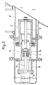
- the valve device G illustrated in Figs. 2 and 3 comprises a main body generally designated by the reference numeral 1 and a piston designated by the reference numeral 2.
- the piston 2 is movable between a retracted position shown in Fig. 2 and an advanced postion shown in Fig 3.
- the piston 2 has at its forward end a face 3 which is inclined to the direction of movement of the piston.
- the valve device includes means 4 to rotate the piston as it moves between its retracted and advanced positions.
- the advancement and rotation of the piston 2 allows the face 3 to adopt a forward position in which it can close an opening 5 in a wall 6 which itself is inclined to the direction of movement of the piston, here inclined through approximately 60°.
- the inclined wall 6 is the upper part of the side wall of a mixer granulator bowl 7.
- the valve device is arranged in a generally horizontal orientation at the base of a vertical chimney 8 which feeds the bowl 7.
- the main body 1 of the valve device comprises a cylindrical piston support 9 and a bearing housing 10.
- Mounted behind the housing 10 is an air cylinder 11, surrounded by an end cover 12.
- a PTFE-coated steel bearing 13 is located within housing 10, and a reciprocating thrust rod 14 extends rearwardly from the bearing 13 to the air cylinder 11, by which it is controlled.
- the air cylinder 11 contains a piston (not shown) which is driven by air pressure in a conventional manner.
- the piston 2 comprises a pair of concentric cylinders 15, 15′ fixedly connected together, the above mentioned face 3 closing the forward end of the outer cylinder 15′ at an angle of 60°.
- the face 3 is thus oval-shaped.
- the inner cylinder 15 is movably mounted on the piston support 9 and is closed at its forward end by an end plate 16.
- Thrust rod 17 is connected to the end plate 16 by a locking nut 18 and extends rearwardly within the piston support 9 to the bearing housing 10 where it is fixed to the bearing 13 and thus to the thrust rod 14.
- Rollers 19 are fixed at the rear end of the inner cylinder 15, on opposite sides thereof, and these rollers locate in spiral grooves 24 in the piston support 9, these grooves and rollers forming the above mentioned rotating means 4.
- the valve device is housed within a cylindrical member 20 which is fitted to the base of the chimney 8 via clamps 21.
- the member 20 is also connected to the end cover 12 by clamps 22. These clamps can be easily undone to allow easy access to the valve device if necessary.
- the face 3 is advantageously made from sintered stainless steel which allows the passage of air therethrough.
- compressed air is fed to the chamber forming between cylinders 15 and 15′ via the hollow thrust rod 17 and via air lines (not shown), the air can fluidise the powder to assist the flow into the bowl.
- the valve device is mounted at the base of the chimney 8 so that the leading edge of the piston, in its retracted position, is at the bottom and almost enters the opening 5.
- the trailing edge of the face 3 is at the top and is flush with the wall of the chimney 8.
- the inclination of the face 3 is chosen to be the same as that of the wall 6 of the bowl, but on the opposite side of the vertical, and the spiral grooves 24 extend around 180. and to a length equal to a horizontal distance between the top and bottom edges of the opening 5. Accordingly, by its forward movement, the piston rotates from a position completely free of the opening to a position completely closing that opening.
- the piston is reversed to the position in Fig. 2 by means of the air cylinder.
- the end face which is inclined to the vertical serves to direct any material coming down the chimney into the bowl, and for this purpose the angle of inclination should be at least 60°
- the valve device of the invention is well adapted to an automatic system in which the operation of the mixer granulator is linked to the feed of material to the bowl, the valve device intermittently freeing the opening in the bowl to coincide with the mixer granulator being emptied and fresh material being fed in.
- the feeding of the mixer granulator can thus be achieved in an entirely sealed and sterile manner which is important when pharmaceuticals are being handled.
- the inclined face of the piston can provide a flush internal finish to the inside wall of the bowl. This ensures that no unmixed material is left in the entry port between filling cycles.
- the side-fitting valve also allows the main lid at the top of the bowl to be opened in emergencies without having to remove any feed pipes.
- the bowl could be fitted with two or more valve devices if different materials are fed separately to the mixer granulator, rather than a predetermined blend of materials.
- the valve can be used to control the flow of powders under pressure or liquid under pressure. If pressurized powders or fluids are being fed, the valve would need little modification other than the provision of seals for the piston. It should be noted, however, that in such circumstances the angle of inclination of the end face of the valve may be much less than the 60° mentioned above in connection with powders.
Landscapes
- Chemical & Material Sciences (AREA)
- Chemical Kinetics & Catalysis (AREA)
- Processing And Handling Of Plastics And Other Materials For Molding In General (AREA)
- Accessories For Mixers (AREA)
- Bipolar Transistors (AREA)
- Mechanically-Actuated Valves (AREA)
- Taps Or Cocks (AREA)
- Valve Device For Special Equipments (AREA)
Claims (7)
- Behälter (A), mit einem Einlaß (5) in einer Schrägwand desselben, einer mit dem Einlaß (5) des Behälters (A) in Verbindung stehenden im wesentlichen vertikalen Einlaßrutsche (D), und einer Ventilvorrichtung (G) zum Öffnen und Schließen des Einlasses (5) des Behälters (A), wobei die Ventilvorrichtung (G) einen Kolben (2) aufweist, der zwischen einer zurückgezogenen Position und einer vorgeschobenen Position bewegbar ist, wobei der Kolben (2) an seinem vorderen Ende eine Fläche (3) aufweist, die in Bewegungsrichtung des Kolbens schräg ist, wobei die Ventilvorrichtung (G) ferner eine Einrichtung (4) zum Drehen des Kolbens bei dessen Vorschub- und Rückzugbewegung aufweist, und wobei der Kolben (2) in einer im wesentlichen horizontalen Position angeordnet ist, wodurch die Schrägfläche (3) des Kolbens in dessen vorgeschobener Position den Einlaß (5) des Behälters (A) schließt und in dessen zurückgezogener Position eine abweichende Ausrichtung einnimmt und imstande ist, längs der Einlaßrutsche (D) herabströmendes Material seitwärts in den Behälter (A) abzulenken.
- Behälter nach Anspruch 1, bei dem der Kolben (2) im wesentlichen zylindrisch und an einem zylindrischen Teil (9) angebracht ist, wobei die Dreheinrichtung Spiralnuten (24) in dem zylindrischen Teil (9) und an dem Kolben (2) befestigte Mitnahmeteile (19) oder Spiralnuten (24) in dem Kolben (2) und an dem zylindrischen Teil (9) befestigte Mitnahmeteile (19) aufweist.
- Behälter nach Anspruch 2, bei dem die Spiralnuten (24) sich über 180° erstrecken.
- Behälter nach einem der vorhergehenden Ansprüche, bei dem der Neigungswinkel der Fläche (3) des Kolbens (2) im wesentlichen 60° beträgt.
- Behälter nach einem der vorhergehenden Ansprüche, bei dem die Fläche (3) des Kolbens (2) porös ist.
- Vorrichtung nach einem der vorhergehenden Ansprüche, bei dem der Kolben (2) durch Luftdruck vorgeschoben und zurückgezogen wird.
- Misch-/Granuliermaschine mit einem Behälter nach einem der vorhergehenden Ansprüche.
Priority Applications (1)
| Application Number | Priority Date | Filing Date | Title |
|---|---|---|---|
| AT89310761T ATE101542T1 (de) | 1988-10-20 | 1989-10-19 | Vorrichtung. |
Applications Claiming Priority (2)
| Application Number | Priority Date | Filing Date | Title |
|---|---|---|---|
| GB888824596A GB8824596D0 (en) | 1988-10-20 | 1988-10-20 | Device |
| GB8824596 | 1988-10-20 |
Publications (3)
| Publication Number | Publication Date |
|---|---|
| EP0365323A2 EP0365323A2 (de) | 1990-04-25 |
| EP0365323A3 EP0365323A3 (de) | 1991-05-15 |
| EP0365323B1 true EP0365323B1 (de) | 1994-02-16 |
Family
ID=10645514
Family Applications (1)
| Application Number | Title | Priority Date | Filing Date |
|---|---|---|---|
| EP89310761A Expired - Lifetime EP0365323B1 (de) | 1988-10-20 | 1989-10-19 | Vorrichtung |
Country Status (7)
| Country | Link |
|---|---|
| US (1) | US5074523A (de) |
| EP (1) | EP0365323B1 (de) |
| JP (1) | JPH02154872A (de) |
| AT (1) | ATE101542T1 (de) |
| CA (1) | CA2001033A1 (de) |
| DE (1) | DE68913129D1 (de) |
| GB (1) | GB8824596D0 (de) |
Families Citing this family (2)
| Publication number | Priority date | Publication date | Assignee | Title |
|---|---|---|---|---|
| JP2005214268A (ja) * | 2004-01-28 | 2005-08-11 | Toyooki Kogyo Co Ltd | ガスタンク用止め弁 |
| RU2328647C1 (ru) * | 2006-12-25 | 2008-07-10 | Открытое акционерное общество "Машиностроительное конструкторское бюро "Искра" имени Ивана Ивановича Картукова" | Пневмопривод для управления регулирующим органом |
Family Cites Families (16)
| Publication number | Priority date | Publication date | Assignee | Title |
|---|---|---|---|---|
| CA602350A (en) * | 1960-07-26 | John W. Bolton And Sons | Adjustable port valve | |
| US2028815A (en) * | 1934-06-01 | 1936-01-28 | Franklin Process Company | Valve |
| US2301378A (en) * | 1940-01-30 | 1942-11-10 | Joe A Crista | Tank car |
| US2703584A (en) * | 1949-11-08 | 1955-03-08 | Paul O Mix | Replacement valve |
| DE916807C (de) * | 1951-12-20 | 1954-08-19 | Neue Molkereitechnik G M B H | Absperrventil fuer Rohrleitungen |
| US2838290A (en) * | 1954-06-11 | 1958-06-10 | George N Simpson | Material conditioner |
| GB806485A (en) * | 1956-02-10 | 1958-12-23 | Horace Fritz Beken | Improvements in and relating to valves for tanks, pans and the like |
| US3367365A (en) * | 1966-05-25 | 1968-02-06 | Orbit Valve Co | Valve |
| NL137090C (de) * | 1969-12-30 | |||
| US4120479A (en) * | 1977-04-15 | 1978-10-17 | Bettis Corporation | Rising stem valve actuator |
| JPS5943216B2 (ja) * | 1981-06-23 | 1984-10-20 | 株式会社奈良機械製作所 | 混合・造粒・乾燥機 |
| JPS5999176A (ja) * | 1982-08-11 | 1984-06-07 | Asuka Kogyo Kk | 切換弁 |
| US4436280A (en) * | 1982-09-30 | 1984-03-13 | Daniel Industries, Inc. | Valve actuator mechanism for lift-turn type valves |
| US4504038A (en) * | 1983-04-25 | 1985-03-12 | King Ottis W | Valve actuator |
| DE3438130A1 (de) * | 1984-10-18 | 1986-04-24 | Lars Mölnlycke Johansson | Vorrichtung zur volumetrischen Dosierung und Zugabe von mindestens zwei Mischstoffen |
| DE3717239C1 (de) * | 1987-05-22 | 1988-08-25 | Hans-Joachim Titus | Absperrventil |
-
1988
- 1988-10-20 GB GB888824596A patent/GB8824596D0/en active Pending
-
1989
- 1989-10-19 EP EP89310761A patent/EP0365323B1/de not_active Expired - Lifetime
- 1989-10-19 US US07/423,874 patent/US5074523A/en not_active Expired - Fee Related
- 1989-10-19 JP JP1272768A patent/JPH02154872A/ja active Pending
- 1989-10-19 CA CA002001033A patent/CA2001033A1/en not_active Abandoned
- 1989-10-19 DE DE89310761T patent/DE68913129D1/de not_active Expired - Lifetime
- 1989-10-19 AT AT89310761T patent/ATE101542T1/de not_active IP Right Cessation
Also Published As
| Publication number | Publication date |
|---|---|
| US5074523A (en) | 1991-12-24 |
| CA2001033A1 (en) | 1990-04-20 |
| ATE101542T1 (de) | 1994-03-15 |
| JPH02154872A (ja) | 1990-06-14 |
| DE68913129D1 (de) | 1994-03-24 |
| EP0365323A3 (de) | 1991-05-15 |
| GB8824596D0 (en) | 1988-11-23 |
| EP0365323A2 (de) | 1990-04-25 |
Similar Documents
| Publication | Publication Date | Title |
|---|---|---|
| JP2688676B2 (ja) | 容器を充填及び空にする移送閉鎖弁 | |
| US7128107B2 (en) | Device for dispensing flowable material components | |
| EP0365323B1 (de) | Vorrichtung | |
| KR101999212B1 (ko) | 정량 공급 장치 | |
| US5385058A (en) | Method and apparatus for sampling particulate material falling from a belt conveyor | |
| US3669318A (en) | Feeder for high pressure autoclave | |
| US3780991A (en) | Proportioning hopper for granular materials | |
| CN217263360U (zh) | 下料机构及配料装置 | |
| US5217173A (en) | Waste processing system | |
| US4572274A (en) | Device for compacting granular molding materials | |
| US5192188A (en) | Lock for the loading and/or discharging of bulk materials | |
| US3874560A (en) | Pneumatic conveyors | |
| KR910700186A (ko) | 미립 재료용 피더 | |
| US5819992A (en) | Multi chamber transfer device | |
| CN116767890A (zh) | 一种化工原料仓储式料仓 | |
| US4557403A (en) | Dry feeder for finely divided solids into high pressure atmosphere | |
| JPS6087121A (ja) | 粉粒体の投入供給装置 | |
| KR100310202B1 (ko) | 액상물 자동 포장장치 | |
| JPS62102826A (ja) | 乾式供給機 | |
| GB2347666A (en) | A dosing device and a method for dosed feeding of grained, pelletized or granulated mass material out from a container | |
| SU1188053A1 (ru) | Устройство дл растаривани мешков с сыпучим материалом | |
| KR950011243B1 (ko) | 드럼관 내용물의 배출장치 | |
| US5984671A (en) | Sealing device useful for providing air-seal self-controlled discharge of product from a process equipment such as a vertical shaft kiln | |
| US3941426A (en) | Apparatus for handling flowable material | |
| JPH0718636Y2 (ja) | 容器排出口の自動開閉装置 |
Legal Events
| Date | Code | Title | Description |
|---|---|---|---|
| PUAI | Public reference made under article 153(3) epc to a published international application that has entered the european phase |
Free format text: ORIGINAL CODE: 0009012 |
|
| AK | Designated contracting states |
Kind code of ref document: A2 Designated state(s): AT BE CH DE FR GB IT LI NL SE |
|
| PUAL | Search report despatched |
Free format text: ORIGINAL CODE: 0009013 |
|
| AK | Designated contracting states |
Kind code of ref document: A3 Designated state(s): AT BE CH DE FR GB IT LI NL SE |
|
| 17P | Request for examination filed |
Effective date: 19911108 |
|
| 17Q | First examination report despatched |
Effective date: 19920720 |
|
| GRAA | (expected) grant |
Free format text: ORIGINAL CODE: 0009210 |
|
| AK | Designated contracting states |
Kind code of ref document: B1 Designated state(s): AT BE CH DE FR GB IT LI NL SE |
|
| PG25 | Lapsed in a contracting state [announced via postgrant information from national office to epo] |
Ref country code: FR Free format text: THE PATENT HAS BEEN ANNULLED BY A DECISION OF A NATIONAL AUTHORITY Effective date: 19940216 Ref country code: IT Free format text: LAPSE BECAUSE OF FAILURE TO SUBMIT A TRANSLATION OF THE DESCRIPTION OR TO PAY THE FEE WITHIN THE PRE;WARNING: LAPSES OF ITALIAN PATENTS WITH EFFECTIVE DATE BEFORE 2007 MAY HAVE OCCURRED AT ANY TIME BEFORE 2007. THE CORRECT EFFECTIVE DATE MAY BE DIFFERENT FROM THE ONE RECORDED.SCRIBED TIME-LIMIT Effective date: 19940216 Ref country code: CH Effective date: 19940216 Ref country code: DE Effective date: 19940216 Ref country code: BE Effective date: 19940216 Ref country code: LI Effective date: 19940216 Ref country code: AT Effective date: 19940216 Ref country code: SE Effective date: 19940216 Ref country code: NL Effective date: 19940216 |
|
| REF | Corresponds to: |
Ref document number: 101542 Country of ref document: AT Date of ref document: 19940315 Kind code of ref document: T |
|
| REF | Corresponds to: |
Ref document number: 68913129 Country of ref document: DE Date of ref document: 19940324 |
|
| REG | Reference to a national code |
Ref country code: CH Ref legal event code: PL |
|
| EN | Fr: translation not filed | ||
| NLV1 | Nl: lapsed or annulled due to failure to fulfill the requirements of art. 29p and 29m of the patents act | ||
| PLBE | No opposition filed within time limit |
Free format text: ORIGINAL CODE: 0009261 |
|
| STAA | Information on the status of an ep patent application or granted ep patent |
Free format text: STATUS: NO OPPOSITION FILED WITHIN TIME LIMIT |
|
| 26N | No opposition filed | ||
| REG | Reference to a national code |
Ref country code: GB Ref legal event code: IF02 |
|
| PGFP | Annual fee paid to national office [announced via postgrant information from national office to epo] |
Ref country code: GB Payment date: 20080915 Year of fee payment: 20 |
|
| REG | Reference to a national code |
Ref country code: GB Ref legal event code: PE20 Expiry date: 20091018 |
|
| PG25 | Lapsed in a contracting state [announced via postgrant information from national office to epo] |
Ref country code: GB Free format text: LAPSE BECAUSE OF EXPIRATION OF PROTECTION Effective date: 20091018 |