EP0365497A2 - Appareil auto-centrant pour l'affûtage des inserts en métal dur des trépans - Google Patents
Appareil auto-centrant pour l'affûtage des inserts en métal dur des trépans Download PDFInfo
- Publication number
- EP0365497A2 EP0365497A2 EP89850273A EP89850273A EP0365497A2 EP 0365497 A2 EP0365497 A2 EP 0365497A2 EP 89850273 A EP89850273 A EP 89850273A EP 89850273 A EP89850273 A EP 89850273A EP 0365497 A2 EP0365497 A2 EP 0365497A2
- Authority
- EP
- European Patent Office
- Prior art keywords
- grinding
- arrangement
- grinding machine
- terised
- charac
- Prior art date
- Legal status (The legal status is an assumption and is not a legal conclusion. Google has not performed a legal analysis and makes no representation as to the accuracy of the status listed.)
- Granted
Links
Images


Classifications
-
- B—PERFORMING OPERATIONS; TRANSPORTING
- B24—GRINDING; POLISHING
- B24B—MACHINES, DEVICES, OR PROCESSES FOR GRINDING OR POLISHING; DRESSING OR CONDITIONING OF ABRADING SURFACES; FEEDING OF GRINDING, POLISHING, OR LAPPING AGENTS
- B24B47/00—Drives or gearings; Equipment therefor
- B24B47/22—Equipment for exact control of the position of the grinding tool or work at the start of the grinding operation
-
- B—PERFORMING OPERATIONS; TRANSPORTING
- B24—GRINDING; POLISHING
- B24B—MACHINES, DEVICES, OR PROCESSES FOR GRINDING OR POLISHING; DRESSING OR CONDITIONING OF ABRADING SURFACES; FEEDING OF GRINDING, POLISHING, OR LAPPING AGENTS
- B24B3/00—Sharpening cutting edges, e.g. of tools; Accessories therefor, e.g. for holding the tools
- B24B3/24—Sharpening cutting edges, e.g. of tools; Accessories therefor, e.g. for holding the tools of drills
- B24B3/33—Sharpening cutting edges, e.g. of tools; Accessories therefor, e.g. for holding the tools of drills of drills for stone
-
- B—PERFORMING OPERATIONS; TRANSPORTING
- B24—GRINDING; POLISHING
- B24B—MACHINES, DEVICES, OR PROCESSES FOR GRINDING OR POLISHING; DRESSING OR CONDITIONING OF ABRADING SURFACES; FEEDING OF GRINDING, POLISHING, OR LAPPING AGENTS
- B24B27/00—Other grinding machines or devices
- B24B27/033—Other grinding machines or devices for grinding a surface for cleaning purposes, e.g. for descaling or for grinding off flaws in the surface
- B24B27/04—Grinding machines or devices in which the grinding tool is supported on a swinging arm
-
- Y—GENERAL TAGGING OF NEW TECHNOLOGICAL DEVELOPMENTS; GENERAL TAGGING OF CROSS-SECTIONAL TECHNOLOGIES SPANNING OVER SEVERAL SECTIONS OF THE IPC; TECHNICAL SUBJECTS COVERED BY FORMER USPC CROSS-REFERENCE ART COLLECTIONS [XRACs] AND DIGESTS
- Y10—TECHNICAL SUBJECTS COVERED BY FORMER USPC
- Y10T—TECHNICAL SUBJECTS COVERED BY FORMER US CLASSIFICATION
- Y10T409/00—Gear cutting, milling, or planing
- Y10T409/30—Milling
- Y10T409/306664—Milling including means to infeed rotary cutter toward work
- Y10T409/30756—Machining arcuate surface
- Y10T409/307616—Machining arcuate surface with means to move cutter eccentrically
Definitions
- the present invention relates to a self-centering grinding arrangement for grinding the hardmetal pins or working tips of drill bits and more specifically, but not exclusively, for grinding the tungsten carbide buttons of button bits of the kind used, e.g., for drilling wells or like down-the-hole drilling operations in the mining industry.
- the arrangement includes a stationary holder arrangement in which the drill bits are clamped and which accommodates a liquid -coolant collecting vessel.
- the arrangement also includes a grinding machine equipped with a grinding pin which rotates about its longitudinal axis, and a grinding machine journalling device which extends at an angle to the longitudinal axis of said pin. The journalling device functions to impart rotary motion to the grinder, with the center of rotation lying in the center of the grinding pin.
- the bit to be ground is clamped in a fixture or jig which can be moved freely on an electromagnetic table, when the table is not magnetic.
- the fixture in which the bit is clamped is brought into approximate alignment with the grinding machine, whereafter the jib arm is lowered, so as to bring the grinding pin into engagement with the carbide button of the bit to be ground. Since, at this stage, the fixture is able to move freely on the table, it is said that the carbide button will center itself in relation to the grinding pin.
- the table is brought to its magnetic state, such as to lock the fixture in position on the table.
- This known grinding arrangement thus includes a holder arrangement which can be moved in the horizontal plane.
- a similar grinding arrangement is described and illustrated in Swedish Patent Application No. 8702950-0, in which the bit holder arrangement includes a carriage which runs on a platform and which can be raised and lowered relative to the grinding machine.
- the grinding machine is attached to the top of a stand or frame and is mounted for limited vertical movement therein.
- the grinding machine journalling device is moveable both horizontally and vertically in relation to the bit holder, which is stationarily mounted.
- the grinding machine journalling device is carried on pairs of mutually parallel arms which are journalled for rotation on a vertically extending stand or frame structure and which co-act with pneumatic piston-cylinder devices.
- the cylinder infeed pressure can be switched to a grinding pressure mode, in which grinding pressure acts vertically during a grinding operation, and a compensating, auxiliary pressure mode for facilitating manual movement of the grinding machine.
- the inventive grinding arrangement enables the grinding pin setting to be readily adjusted manually, due to the fact that the weight of the grinding machine is counteracted by the compensating functions of the piston-cylinder devices, i.e. the aforesaid auxiliary pressure mode.
- a self-centering effect, or fine adjustment of the grinding pin setting is achieved automatically, by switching the cylinder input pressure to the grinding pressure mode. Due to the full freedom of movement of the inventive grinding machine journalling device in all space planes, it is possible to grind a multiple of drill bits in a rational manner.
- the stationary bit holder arrangement can be provided with two bit holders for a corresponding number of bits.
- the grinding machine journalling device can be swung to a position in which it is located above respective holders, or above a drill bit which, because of its dimensions, has been located outside the holder arrangement, and the cylinder input pressure then switched to its grinding pressure mode.
- the holders provided in the holder arrangement preferivelyably have the form of recesses located in at least one tiltable table which is capable of being stopped and locked in desired angular positions and which has mounted beneath its upper surface,i.e. the table top, a pneumatically operated piston rod for each holder.
- a well-defined location of the drill bit in respective holders can be achieved by providing each recess with a corner piece and by directing piston movement towards said corner piece, the stem of the bit being inserted into the recess and clamped against the corner piece by means of the activated piston rod.
- the tiltable table is provided with a bottom plate which can be displaced positionally beneath the recess, such as to allow smaller drill bits having relatively short stems to rest against the plate.
- each table is provided with an individual journalling device and therewith with an individual grinding machine.
- This embodiment greatly rationalises the handling of drill bits to be ground, since two bits can be ground simultaneously, while the operator is able to remove a ground bit from one table and insert in the adjacent holder a fresh bit to be ground, in respective tables.
- the holder arrangement and associated collecting vessel are constructed so as to function as a transport container for transportation of the grinding arrangement in its dismantled state, the grinding arrangement components being accommodated in the transport container.
- FIG 1 illustrates the principle construction of a grinding arrangement according to the present invention.
- the grinding arrangement comprises a bit holding arrangement for those bits whose tungsten carbide buttons 31 are to be ground.
- the arrangement also includes a jour nalling device 4 which is intended to carry a grinding machine 3.
- the grinding machine 3 includes a drive motor which rotates a grinding pin 15 at high speed about its longitudinal axis.
- the journalling device also includes a further drive motor which has a shaft 24 on which the grinding machine 3 can be adjustably mounted, by means of an attachment means 25.
- the drive motor of the journalling device 4 is operative to impart circuitous or orbital movement to the grinding machine 3 and its grinding pin 15, with the center of rotation in the grinding center 30 of the grinding pin 15 (Fig. 2).
- the journalling device is carried by parallel arm pairs 5, 7 which are journalled on a post or column 6 for rotation through an angle of 360°.
- the post 6 is mounted on a floor frame 17.
- Each of the parallel arm pairs 5, 7 includes an inner and an outer arm pair 9 and 10 respectively, such that the journalling device 4 and the grinding machine carried thereby can be moved freely, both vertically and horizontally, within the span of the parallel arm pairs 5, 7.
- the grinding pin 15 is brought manually into alignment with the tungsten carbide button to be ground, by gripping a handle 8 and moving the grinding pin 15 to a position immediately above the button 31. This manual movement is facilitated by a double-acting, pneumatic compensating piston-cylinder device 11, 12 provided between the pivotal arms within respective arm pairs 9, 10.
- the supply circuits of the piston-cylinder-devices also include a switch 14 which is operative to switch the direction of air supply, such as to cause the parallel arm pairs 5, 7 to exert a vertical downward force on the journalling device 4 and the grinding machine 3. This facility is utilised for the automatic, continuous grinding operation described herebelow.
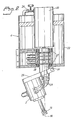
- FIG. 2 illustrates the principle construction of the journalling device 4.
- the main components of this device include a housing 22, which houses the further drive motor 23 and its output shaft 24.
- the drive motor is supplied with air under pressure from the same conduit as that used to supply air under pressure to the grinding machine 3.
- a throttle valve 26 Arranged in the branch leading to the drive motor 23 is a throttle valve 26, by means of which the operator can regulate the flow of air to the further drive motor 23 and control the speed of said motor from zero to maximum values.
- the output shaft 24 is journalled in the housing 22 on two ball bearings 27 and has provided therein three passageways which are supplied with air to and from the grinding machine 3 and with cooling water to said machine, via a swivel switch 28.
- the passageways are connected to the grinding machine 3 by hoses 29.
- the grinding machine attachment 25 is attached to the lower end of the output shaft 24 at a given angle which is so adapted that the grinding center 30 of the grinding pin 15 will coincide with the rotational axis of the output shaft 24, despite the fact that the grinding machine is angularly positioned.
- the drive motor 23 will drive the grinding machine 3 in a circuit path during a grinding operation, therewith providing a highly satisfactory grinding result.
- the attachment 25 can be adjusted to mutually different angular positions for adaptation to the angular position of the drill bit to be ground.
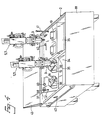
- Figures 3a and 3b illustrate a preferred embodiment of the inventive grinding arrangement.
- the arrangement is shown in side view in Figure 3a and in front view in Figure 3b.
- the majority of the reference numerals used in Figures 3a and 3b are found in Figure 1 and identify mutually corresponding components of the two embodiments.
- the journalling device 4 suspended from the parallel arm pairs 5, 7 includes supply devices for air supply A, B and cooling water supply C, each said supply device being connected, via the swivel switch or coupling, to the grinding machine by a respective pivotal pipe A′, B′, C′, these pipes corresponding to the hoses 29 of the Figure 1 embodiment.
- the conduit A incorporates the throttle valve 26 referred to with reference to Figure 2.
- FIGS 3a and 3b illustrate more clearly the preferred embodiment of the adjustable attachment means 25.
- This attachment means includes a casing which has formed therein two arcuate grooves or channels for coaction with locking pins and locking devices 33 associated therewith, thereby enabling the position of the grinding machine to be fixated relative to the journalling device 4.
- the angle subtended between the longitudinal axis of the grinding pin 15 and the longitudinal axis of the drive shaft 24 can therefore be controlled, which is desirable for effective control of the amplitude of the orbital or circuitous movement before mentioned.
- FIG 4 illustrates a preferred embodiment of a drill-bit holder arrangement 2 intended for holding the drill bits whose tungsten carbide buttons 31 are to be ground.
- the holder arrangement comprises a box 18 having an upwardly facing opening 34 in which one or more tables 35 are pivotably mounted, as indicated by the axle 20 and the arrow 21 in Figure 1.
- Each table 35 includes two or more holders 19 in the form of substantially rectangular recesses, into which the stem of the drill bit 1 is inserted.
- the holder 19 also includes a pneumatic piston-cylinder device whose piston 36 functions to hold the drill bit 1 locked effectively against the walls of said recesses.
- the piston-cylinder device of respective holders 19 is preferably arranged such that the piston of each said device will operate in the direction of one diagonal of the recesses, therewith to lock the drill bit 1 effectively against one corner of the recesses, as will be seen from the table 35 shown to the left in Figure 4.
- the piston-cylinder devices of the holders 19 are operated by means of a valve 37, which is housed in a casing 38 in order to shield the valve against unintentional activation. Consequently, the operator can only activate the valve 37 from the mutually opposite open sides. When activated from one side, the valve 37 will operate to impart locking movement to the piston cyl inder-device, and when activated from the other side will impart a release movement to said device.
- the holder 19 is provided with a displaceable floor 39, which enables the holder to accommodate drills of small dimensions in a ready manner.
- the floor 39 is displaced with the aid of a lever 40.
- the floor 39 of the left-hand table 35 is shown to be displaced to a position in which it will support drill bits 1 of small dimensions.
- the floor 39 of the right-hand table of the illustration has been moved away, so as to enable drill bits 1 of large dimensions to be fitted, the head diameters of these bits being so large as to allow the heads to rest on the surface of the floor 39, when the drill stem is inserted into one of the holder recessess of the table.
- each table can be adjusted to a desired angular position. This adjustment is facilitated by means of a lever 41, which can be pulled or drawn up in the manner shown at the right-hand table in Figure 4.
- the table can be locked in its selected position, by means of a locking device 42.
- the box 18 serves as a collecting vessel for the liquid coolant delivered to the grinding location from the grinding machine during a grinding process.
- Detachable splash guards 43 can be fitted to all side walls of the box 18.
- the box 18 is connected to a circulation pump and filter arrangement, for recycling the liquid coolant to the grinding machine 3.
- a further advantage afforded by the box 18 is that the box is adapted to accommodate the whole of the grinding arrangement. Subsequent to being dismantled to a given extent, the grinding arrangement can be packed into the box 18, which then serves as a transportation crate.
- the illustrated preferred embodiment of the holder arrangement 2 comprising two tables 35 which can be manouvered independently of one another, can be assigned two grinding machines 3, each journalled in parallel arm pairs 5, 7. This enables drill bits of mutually different dimensions to be ground separately at one and the same time.
- the possibility is afforded of switching bits in one of the holders while grinding a bit in the other.
- the drill bits 1 whose tungsten carbide buttons 31 are to be ground are clamped in respective holders 19 on the tables 35.
- the tables are then inclined to positions for grinding the buttons located on the crown or periphery of respective bits.
- the grinding pin 15 of the grinding machine 3 is then moved forwards to the first button 31 to be ground.
- compressed air is supplied to the compensating piston-cylinder devices 11, 12 of the parallel arm pairs 5, 7, so as to enable the operator to bring the grinding pin 15 manually into position, centrally above the button 31, in a ready and easy fashion.
- the operator manipulates the switch 14, so as to switch the supply of compressed air from the compensating piston-cylinder devices 11, 12 to the grinding pressure facility, while starting the drive motors 3 and 23 at the same time.
- the grinding pin 15 will automatically find its correct grinding position on the tungsten carbide button 31, through a self-centering action, and grinding is commenced.
- the operator is able to exchange ground bits for fresh, worn bits in a holder located adjacent the holder containing the bit being ground. Subsequent hereto, there remains nothing else for the operator to do, other than to switch off the grinding arrangement when grinding of said bit is completed.
- the switch 14 is turned to its compensating position and the grinding pin 15 is moved manually to a fresh button to be ground. The aforesaid automatic self-centering action and subsequent grinding procedure are then repeated.
- the parallel arm pairs can be rotated on the post 6 to a position externally of the box 18.
- the drill bits of excessively large dimensions can be clamped in this position with the aid of suitable means and the tungsten carbide buttons thereof ground with the aid of the same machine used to grind the drill bits of smaller dimensions.
- the drill bit holder can be configured in a manner which will tailor the holder to a drill bit of particular manufacture.
- the arrangement may include a pump system operative to pump liquid coolant from the collecting vessel 18 back to the grinding machine 3.
Landscapes
- Engineering & Computer Science (AREA)
- Mechanical Engineering (AREA)
- Finish Polishing, Edge Sharpening, And Grinding By Specific Grinding Devices (AREA)
- Earth Drilling (AREA)
- Drilling And Boring (AREA)
- Pharmaceuticals Containing Other Organic And Inorganic Compounds (AREA)
- Professional, Industrial, Or Sporting Protective Garments (AREA)
- Perforating, Stamping-Out Or Severing By Means Other Than Cutting (AREA)
- Grinding And Polishing Of Tertiary Curved Surfaces And Surfaces With Complex Shapes (AREA)
Priority Applications (1)
| Application Number | Priority Date | Filing Date | Title |
|---|---|---|---|
| AT89850273T ATE86907T1 (de) | 1988-10-17 | 1989-08-25 | Selbstzentrierende einrichtung zum schaerfen der hartmetalleinsaetze von bohrkronen. |
Applications Claiming Priority (2)
| Application Number | Priority Date | Filing Date | Title |
|---|---|---|---|
| SE8803684 | 1988-10-17 | ||
| SE8803684A SE462901B (sv) | 1988-10-17 | 1988-10-17 | Anordning foer slipning av stiften paa borrkronor |
Publications (3)
| Publication Number | Publication Date |
|---|---|
| EP0365497A2 true EP0365497A2 (fr) | 1990-04-25 |
| EP0365497A3 EP0365497A3 (en) | 1990-09-19 |
| EP0365497B1 EP0365497B1 (fr) | 1993-03-17 |
Family
ID=20373643
Family Applications (1)
| Application Number | Title | Priority Date | Filing Date |
|---|---|---|---|
| EP89850273A Expired - Lifetime EP0365497B1 (fr) | 1988-10-17 | 1989-08-25 | Appareil auto-centrant pour l'affûtage des inserts en métal dur des trépans |
Country Status (15)
| Country | Link |
|---|---|
| US (1) | US5070654A (fr) |
| EP (1) | EP0365497B1 (fr) |
| JP (2) | JPH02160466A (fr) |
| KR (1) | KR0162636B1 (fr) |
| CN (1) | CN1015784B (fr) |
| AT (1) | ATE86907T1 (fr) |
| AU (1) | AU607353B2 (fr) |
| BR (1) | BR8904607A (fr) |
| CA (1) | CA1325108C (fr) |
| DE (1) | DE68905427T2 (fr) |
| FI (1) | FI894000L (fr) |
| NO (1) | NO172105C (fr) |
| RU (1) | RU1838090C (fr) |
| SE (2) | SE462901B (fr) |
| ZA (1) | ZA896846B (fr) |
Cited By (7)
| Publication number | Priority date | Publication date | Assignee | Title |
|---|---|---|---|---|
| EP0472508A1 (fr) * | 1990-08-17 | 1992-02-26 | C.M.E. Construction-Mining-Equipment Ab | Appareil à rectifier non-rotatif |
| EP0861705A3 (fr) * | 1993-06-22 | 2000-11-15 | Sandvik Aktiebolag | Calotte de meulage |
| WO2002004169A3 (fr) * | 2000-07-10 | 2002-04-11 | C M S Blasting & Mining Equipm | Améliorations apportées à une machine à meuler |
| WO2004073923A1 (fr) * | 2003-02-19 | 2004-09-02 | C.M.E. Blasting & Mining Equipment Ltd. | Appareil de meulage de boutons presents sur le trepan de forage de roche |
| WO2007102764A1 (fr) * | 2006-03-09 | 2007-09-13 | Sandvik Intellectual Property Ab | Machine a meuler et procede pour meuler des boutons d'une tete de forage de roche |
| WO2018152562A1 (fr) * | 2017-02-21 | 2018-08-30 | Montrae Mining Pty Ltd | Affûteur de trépan |
| WO2018236268A1 (fr) * | 2017-06-21 | 2018-12-27 | Winroth Industri Ab | Machine de meulage avec moteurs hydrauliques |
Families Citing this family (32)
| Publication number | Priority date | Publication date | Assignee | Title |
|---|---|---|---|---|
| SE9201835L (sv) * | 1992-06-15 | 1993-10-18 | Uniroc Grinding Ab | Vibrationsdämpande slipkopp för slipning av hårdmetallstift hos stiftborrkronor och hållare för en sådan slipkopp |
| GB9217020D0 (en) * | 1992-08-11 | 1992-09-23 | Redfern Gary | Grinding apparatus |
| SE503183C2 (sv) * | 1993-12-14 | 1996-04-15 | Sandvik Ab | Förfarande och anordning för att slipa stift hos en bergborrkrona och spolhuvud för att tillföra spolmedium vid slipningen av stiften hos en dylik bergborrkrona |
| SE504443C2 (sv) * | 1994-11-21 | 1997-02-10 | Sandvik Ab | Slipkopp samt slitdel därtill |
| DE69610820T2 (de) * | 1995-02-03 | 2001-03-01 | C.M.E. Blasting & Mining Equipment Ltd., Ontario | Topfschleifscheibe und schleifscheibenhalter |
| US5639273A (en) * | 1995-02-03 | 1997-06-17 | C.M.E. Blasting & Mining Equipment Ltd. | Grinding cup and holder device |
| JP3570833B2 (ja) * | 1996-12-04 | 2004-09-29 | ミヤモトエンジニアリング株式会社 | ドリル研磨方法 |
| EP0919327B1 (fr) * | 1997-12-01 | 2004-11-03 | HAWE NEOS DENTAL Dr. H. V. WEISSENFLUH AG | Dispositif pour aiguiser des instruments dentaires |
| SE512081C2 (sv) * | 1998-06-26 | 2000-01-24 | Sandvik Ab | Fixtur och slipmaskin för att slipa stift hos en bergborrkrona |
| CA2300315A1 (fr) * | 2000-03-09 | 2001-09-09 | Bo Thomas Sjolander | Coupelle de meulage de masse reduite |
| US7811155B2 (en) * | 2001-11-21 | 2010-10-12 | Cme Blasting & Mining Equipment Ltd. | Grinding member for buttons on rock drill bit |
| SE526439C2 (sv) * | 2003-03-10 | 2005-09-13 | Atlas Copco Secoroc Ab | Slipmaskin för slipning av stiftborrkronor |
| SE527994C2 (sv) * | 2004-12-15 | 2006-08-01 | Atlas Copco Secoroc Ab | Inställningsarrangemang för en slipmaskin för slipning av stiftborrkronor |
| US20060131283A1 (en) * | 2004-12-17 | 2006-06-22 | Lsi Logic Corporation | Method and apparatus for forming angled vias in an integrated circuit package substrate |
| FI126233B (sv) * | 2006-02-23 | 2016-08-31 | Oy Kwh Mirka Ab | Oscillerande slipmaskin |
| CA2636995A1 (fr) * | 2008-07-08 | 2010-01-08 | C.M.E. Blasting & Mining Equipment Ltd. | Dispositif de verrouillage manuel pour porte-fleuret avec reglage micro ou macrometrique |
| JP2010099811A (ja) * | 2008-10-27 | 2010-05-06 | Fujitsu Ltd | 研磨装置 |
| IT1396809B1 (it) * | 2009-05-15 | 2012-12-14 | Re Ma Sas Di Pressato Emanuele & C | Macchina affilatrice portatile per affilare punte da legno |
| US20110097157A1 (en) * | 2009-10-26 | 2011-04-28 | Illinois Tool Works Inc. | Deep Water Pipe Preparation Machine |
| US8961077B2 (en) * | 2009-10-26 | 2015-02-24 | Illlinois Tool Works Inc. | Severing and beveling tool |
| US20110097979A1 (en) * | 2009-10-26 | 2011-04-28 | Illinois Tool Works Inc. | Fusion Bonded Epoxy Removal Tool |
| CN102120305A (zh) * | 2010-12-23 | 2011-07-13 | 山西力天世纪刀具有限公司 | 一种用于加工金刚石球形面的磨床 |
| US8926407B2 (en) * | 2011-11-01 | 2015-01-06 | Illinois Tool Works Inc. | Devices and methods for removing a coating on a surface of a submerged pipeline |
| CN102699878B (zh) * | 2012-02-08 | 2015-01-14 | 苏州喜和喜精密机械有限公司 | 倒钝砂抛钻攻复合机 |
| CA2823643A1 (fr) * | 2013-08-12 | 2015-02-12 | Bo Thomas Sjolander | Appareil de broyage avec commande de charge non pneumatique |
| MX370557B (es) | 2013-10-03 | 2019-12-17 | Illinois Tool Works | Soporte de herramientas giratorio para un aparato de maquinado de tubos. |
| CN104551950B (zh) * | 2015-01-31 | 2016-09-14 | 南通恒鼎重型机床有限公司 | 一种大型罐体外壁抛光装置 |
| CN106826426B (zh) * | 2017-01-09 | 2019-10-29 | 中国第一汽车股份有限公司 | 刃口研磨机 |
| CN107322378A (zh) * | 2017-09-01 | 2017-11-07 | 贵州迈锐钻探设备制造有限公司 | 一种钻头修磨机 |
| DE102019002054A1 (de) * | 2019-03-22 | 2020-09-24 | Vollmer Werke Maschinenfabrik Gmbh | Vorrichtung und Verfahren zum Bearbeiten von gleichartigen Werkstücken |
| CN109940484A (zh) * | 2019-04-26 | 2019-06-28 | 四川天府珞埔三维科技有限公司 | 一种义齿自动打磨装置 |
| CN119952483B (zh) * | 2025-03-31 | 2025-09-05 | 锦美运动用品(东莞)有限公司 | 一种高尔夫球杆成型设备 |
Family Cites Families (14)
| Publication number | Priority date | Publication date | Assignee | Title |
|---|---|---|---|---|
| US3036409A (en) * | 1960-11-02 | 1962-05-29 | Forrest R Whitcomb | Tool feed control |
| US3279126A (en) * | 1964-02-14 | 1966-10-18 | Lee H Barron | Machine for generating surfaces on hard materials |
| FR2055862A5 (fr) * | 1969-08-01 | 1971-05-14 | Gazuit Georges | |
| US3854250A (en) * | 1973-11-01 | 1974-12-17 | Int Shoe Machine Corp | Roughing machine having counterweighted roughing tool |
| FR2369055A1 (fr) * | 1976-10-29 | 1978-05-26 | Creusot Loire | Dis |
| SE416115B (sv) * | 1977-02-11 | 1980-12-01 | Fagersta Ab | Slipfixtur for slipning av skerstift i bergborrkronor |
| DE2937976C2 (de) * | 1979-09-20 | 1983-02-24 | Prontor-Werk Alfred Gauthier Gmbh, 7547 Wildbad | Maschine zum Schleifen oder Fräsen von konvexen und/oder konkaven sphärischen Flächen |
| JPS58102669A (ja) * | 1981-12-11 | 1983-06-18 | Hitachi Ltd | 曲面研磨用ロボツト |
| IT1159299B (it) * | 1982-07-09 | 1987-02-25 | Ideal Standard Spa | Macchina automatica per la canapatura interna delle apparecchiature igienico-sanitarie in genere |
| AU3583084A (en) * | 1983-12-10 | 1985-06-13 | Aida Engineering Ltd. | Playback grinding robot |
| GB2193456B (en) * | 1986-07-25 | 1990-06-06 | Boart Int Ltd | Restoration of drill buttons |
| US4858388A (en) * | 1986-07-25 | 1989-08-22 | Bice Keith C | Restoration or drill buttons |
| AU589535B2 (en) * | 1986-07-25 | 1989-10-12 | Boart International Limited | Restoration of drill buttons |
| SE460584B (sv) * | 1986-10-01 | 1989-10-30 | Sandvik Ab | Foerfarande och anordning foer slipning av en stiftborrkrona |
-
1988
- 1988-10-17 SE SE8803684A patent/SE462901B/sv not_active IP Right Cessation
-
1989
- 1989-08-22 SE SE8902794A patent/SE467347B/sv not_active IP Right Cessation
- 1989-08-25 NO NO893425A patent/NO172105C/no not_active IP Right Cessation
- 1989-08-25 AT AT89850273T patent/ATE86907T1/de not_active IP Right Cessation
- 1989-08-25 EP EP89850273A patent/EP0365497B1/fr not_active Expired - Lifetime
- 1989-08-25 DE DE89850273T patent/DE68905427T2/de not_active Expired - Fee Related
- 1989-08-25 FI FI894000A patent/FI894000L/fi not_active Application Discontinuation
- 1989-09-07 ZA ZA896846A patent/ZA896846B/xx unknown
- 1989-09-12 AU AU41313/89A patent/AU607353B2/en not_active Expired
- 1989-09-13 BR BR898904607A patent/BR8904607A/pt not_active IP Right Cessation
- 1989-09-25 RU SU894614948A patent/RU1838090C/ru active
- 1989-09-29 CA CA000614472A patent/CA1325108C/fr not_active Expired - Lifetime
- 1989-10-09 JP JP1263793A patent/JPH02160466A/ja active Pending
- 1989-10-14 CN CN89107936A patent/CN1015784B/zh not_active Expired
- 1989-10-16 KR KR1019890014875A patent/KR0162636B1/ko not_active Expired - Lifetime
- 1989-10-16 US US07/422,128 patent/US5070654A/en not_active Expired - Lifetime
-
1994
- 1994-07-22 JP JP010099U patent/JPH0720246U/ja active Pending
Cited By (13)
| Publication number | Priority date | Publication date | Assignee | Title |
|---|---|---|---|---|
| US5193312A (en) * | 1990-08-17 | 1993-03-16 | Gudmundsson Soeren | Non-rotating grinding apparatus |
| EP0472508A1 (fr) * | 1990-08-17 | 1992-02-26 | C.M.E. Construction-Mining-Equipment Ab | Appareil à rectifier non-rotatif |
| EP0861705A3 (fr) * | 1993-06-22 | 2000-11-15 | Sandvik Aktiebolag | Calotte de meulage |
| US7198556B2 (en) | 2000-07-10 | 2007-04-03 | C.M.E. Blasting & Mining Equipment Ltd. | Grinding apparatus |
| WO2002004169A3 (fr) * | 2000-07-10 | 2002-04-11 | C M S Blasting & Mining Equipm | Améliorations apportées à une machine à meuler |
| GB2381768A (en) * | 2000-07-10 | 2003-05-14 | Cme Blasting & Mining Equip | Improved grinding apparatus |
| GB2381768B (en) * | 2000-07-10 | 2004-02-25 | Cme Blasting & Mining Equip | Improved grinding apparatus |
| AU2001272260B2 (en) * | 2000-07-10 | 2006-03-30 | C.M.E. Blasting & Mining Equipment Ltd. | Grinding apparatus with articulated arm |
| WO2004073923A1 (fr) * | 2003-02-19 | 2004-09-02 | C.M.E. Blasting & Mining Equipment Ltd. | Appareil de meulage de boutons presents sur le trepan de forage de roche |
| CN1750905B (zh) * | 2003-02-19 | 2012-04-04 | C.M.E.鼓风及采矿设备有限公司 | 用于研磨凿岩钻头上球齿的研磨设备 |
| WO2007102764A1 (fr) * | 2006-03-09 | 2007-09-13 | Sandvik Intellectual Property Ab | Machine a meuler et procede pour meuler des boutons d'une tete de forage de roche |
| WO2018152562A1 (fr) * | 2017-02-21 | 2018-08-30 | Montrae Mining Pty Ltd | Affûteur de trépan |
| WO2018236268A1 (fr) * | 2017-06-21 | 2018-12-27 | Winroth Industri Ab | Machine de meulage avec moteurs hydrauliques |
Also Published As
| Publication number | Publication date |
|---|---|
| SE8902794L (sv) | 1990-04-18 |
| KR900006079A (ko) | 1990-05-07 |
| SE462901B (sv) | 1990-09-17 |
| NO172105B (no) | 1993-03-01 |
| JPH0720246U (ja) | 1995-04-11 |
| DE68905427D1 (de) | 1993-04-22 |
| SE8902794D0 (sv) | 1989-08-22 |
| ZA896846B (en) | 1990-06-27 |
| KR0162636B1 (ko) | 1999-02-18 |
| AU4131389A (en) | 1990-04-26 |
| CA1325108C (fr) | 1993-12-14 |
| FI894000A0 (fi) | 1989-08-25 |
| ATE86907T1 (de) | 1993-04-15 |
| EP0365497A3 (en) | 1990-09-19 |
| DE68905427T2 (de) | 1993-09-30 |
| JPH02160466A (ja) | 1990-06-20 |
| NO893425L (no) | 1990-04-18 |
| NO893425D0 (no) | 1989-08-25 |
| SE467347B (sv) | 1992-07-06 |
| RU1838090C (ru) | 1993-08-30 |
| SE8803684L (sv) | 1990-04-18 |
| NO172105C (no) | 1993-06-09 |
| CN1041902A (zh) | 1990-05-09 |
| US5070654A (en) | 1991-12-10 |
| FI894000A7 (fi) | 1990-04-18 |
| BR8904607A (pt) | 1990-04-24 |
| EP0365497B1 (fr) | 1993-03-17 |
| CN1015784B (zh) | 1992-03-11 |
| AU607353B2 (en) | 1991-02-28 |
| SE8803684D0 (sv) | 1988-10-17 |
| FI894000L (fi) | 1990-04-18 |
Similar Documents
| Publication | Publication Date | Title |
|---|---|---|
| EP0365497B1 (fr) | Appareil auto-centrant pour l'affûtage des inserts en métal dur des trépans | |
| JP4320186B2 (ja) | ロッド材料にフライス作業および旋削作業を実施するフライス盤 | |
| US6666748B2 (en) | Machining center and method of changing tools thereof | |
| US20030099522A1 (en) | Device for mechanically rough machining and/or finish machining cast parts | |
| CN102089119B (zh) | 快速定位的用于钻头夹持器的手动夹紧装置 | |
| FI125440B (fi) | Hiontalaite, jossa on nivelletty varsi | |
| US4637107A (en) | Machining machine | |
| CN1031113C (zh) | 非旋转式研磨装置 | |
| JP2000317750A (ja) | 万能工作機械 | |
| US4515191A (en) | Radial universal tool | |
| WO2000000325A1 (fr) | Agencement et machine a rectifier les molettes d'un trepan | |
| JPH02250743A (ja) | 心なし研削盤用ワーク供給装置 | |
| JPH05285756A (ja) | 多用途加工機 | |
| US3165977A (en) | Machine tool with an angularly adjustable spindle head | |
| JPH0137851Y2 (fr) | ||
| CN210255416U (zh) | 一种钻头加工机械 | |
| JPH01289651A (ja) | 研削盤 | |
| ZA200300040B (en) | Improved grinding apparatus. | |
| US2418387A (en) | Machine tool | |
| JPH11188596A (ja) | 大型ワークの自動研削装置 | |
| JPH10225866A (ja) | 研削盤 | |
| SK238891A3 (sk) | : Zariadenie na ostrenie nástrojov, najml skrutkových vrtákov |
Legal Events
| Date | Code | Title | Description |
|---|---|---|---|
| PUAI | Public reference made under article 153(3) epc to a published international application that has entered the european phase |
Free format text: ORIGINAL CODE: 0009012 |
|
| AK | Designated contracting states |
Kind code of ref document: A2 Designated state(s): AT BE CH DE ES FR GB GR IT LI LU NL SE |
|
| PUAL | Search report despatched |
Free format text: ORIGINAL CODE: 0009013 |
|
| RHK1 | Main classification (correction) |
Ipc: B24B 3/33 |
|
| AK | Designated contracting states |
Kind code of ref document: A3 Designated state(s): AT BE CH DE ES FR GB GR IT LI LU NL SE |
|
| 17P | Request for examination filed |
Effective date: 19901015 |
|
| 17Q | First examination report despatched |
Effective date: 19920513 |
|
| GRAA | (expected) grant |
Free format text: ORIGINAL CODE: 0009210 |
|
| AK | Designated contracting states |
Kind code of ref document: B1 Designated state(s): AT BE CH DE ES FR GB GR IT LI LU NL SE |
|
| PG25 | Lapsed in a contracting state [announced via postgrant information from national office to epo] |
Ref country code: IT Free format text: LAPSE BECAUSE OF FAILURE TO SUBMIT A TRANSLATION OF THE DESCRIPTION OR TO PAY THE FEE WITHIN THE PRE;WARNING: LAPSES OF ITALIAN PATENTS WITH EFFECTIVE DATE BEFORE 2007 MAY HAVE OCCURRED AT ANY TIME BEFORE 2007. THE CORRECT EFFECTIVE DATE MAY BE DIFFERENT FROM THE ONE RECORDED.SCRIBED TIME-LIMIT Effective date: 19930317 Ref country code: FR Effective date: 19930317 Ref country code: ES Free format text: THE PATENT HAS BEEN ANNULLED BY A DECISION OF A NATIONAL AUTHORITY Effective date: 19930317 Ref country code: NL Effective date: 19930317 Ref country code: SE Effective date: 19930317 Ref country code: BE Effective date: 19930317 Ref country code: GR Free format text: LAPSE BECAUSE OF FAILURE TO SUBMIT A TRANSLATION OF THE DESCRIPTION OR TO PAY THE FEE WITHIN THE PRESCRIBED TIME-LIMIT Effective date: 19930317 |
|
| REF | Corresponds to: |
Ref document number: 86907 Country of ref document: AT Date of ref document: 19930415 Kind code of ref document: T |
|
| REF | Corresponds to: |
Ref document number: 68905427 Country of ref document: DE Date of ref document: 19930422 |
|
| EN | Fr: translation not filed | ||
| PGFP | Annual fee paid to national office [announced via postgrant information from national office to epo] |
Ref country code: AT Payment date: 19930813 Year of fee payment: 5 |
|
| NLV1 | Nl: lapsed or annulled due to failure to fulfill the requirements of art. 29p and 29m of the patents act | ||
| PG25 | Lapsed in a contracting state [announced via postgrant information from national office to epo] |
Ref country code: GB Effective date: 19930825 |
|
| PG25 | Lapsed in a contracting state [announced via postgrant information from national office to epo] |
Ref country code: LU Free format text: LAPSE BECAUSE OF NON-PAYMENT OF DUE FEES Effective date: 19930831 |
|
| PGFP | Annual fee paid to national office [announced via postgrant information from national office to epo] |
Ref country code: CH Payment date: 19931028 Year of fee payment: 5 |
|
| PLBE | No opposition filed within time limit |
Free format text: ORIGINAL CODE: 0009261 |
|
| STAA | Information on the status of an ep patent application or granted ep patent |
Free format text: STATUS: NO OPPOSITION FILED WITHIN TIME LIMIT |
|
| 26N | No opposition filed | ||
| GBPC | Gb: european patent ceased through non-payment of renewal fee |
Effective date: 19930825 |
|
| PG25 | Lapsed in a contracting state [announced via postgrant information from national office to epo] |
Ref country code: DE Effective date: 19940503 |
|
| PG25 | Lapsed in a contracting state [announced via postgrant information from national office to epo] |
Ref country code: AT Effective date: 19940825 |
|
| PG25 | Lapsed in a contracting state [announced via postgrant information from national office to epo] |
Ref country code: LI Effective date: 19940831 Ref country code: CH Effective date: 19940831 |
|
| REG | Reference to a national code |
Ref country code: CH Ref legal event code: PL |