EP0365555B1 - Verfahren und gerät zur fehlerkorrektur - Google Patents
Verfahren und gerät zur fehlerkorrektur Download PDFInfo
- Publication number
- EP0365555B1 EP0365555B1 EP88905286A EP88905286A EP0365555B1 EP 0365555 B1 EP0365555 B1 EP 0365555B1 EP 88905286 A EP88905286 A EP 88905286A EP 88905286 A EP88905286 A EP 88905286A EP 0365555 B1 EP0365555 B1 EP 0365555B1
- Authority
- EP
- European Patent Office
- Prior art keywords
- registers
- discrepancy
- contents
- coefficient
- syndrome
- Prior art date
- Legal status (The legal status is an assumption and is not a legal conclusion. Google has not performed a legal analysis and makes no representation as to the accuracy of the status listed.)
- Expired - Lifetime
Links
Images


Classifications
-
- H—ELECTRICITY
- H03—ELECTRONIC CIRCUITRY
- H03M—CODING; DECODING; CODE CONVERSION IN GENERAL
- H03M13/00—Coding, decoding or code conversion, for error detection or error correction; Coding theory basic assumptions; Coding bounds; Error probability evaluation methods; Channel models; Simulation or testing of codes
- H03M13/03—Error detection or forward error correction by redundancy in data representation, i.e. code words containing more digits than the source words
- H03M13/05—Error detection or forward error correction by redundancy in data representation, i.e. code words containing more digits than the source words using block codes, i.e. a predetermined number of check bits joined to a predetermined number of information bits
- H03M13/13—Linear codes
- H03M13/15—Cyclic codes, i.e. cyclic shifts of codewords produce other codewords, e.g. codes defined by a generator polynomial, Bose-Chaudhuri-Hocquenghem [BCH] codes
-
- H—ELECTRICITY
- H03—ELECTRONIC CIRCUITRY
- H03M—CODING; DECODING; CODE CONVERSION IN GENERAL
- H03M13/00—Coding, decoding or code conversion, for error detection or error correction; Coding theory basic assumptions; Coding bounds; Error probability evaluation methods; Channel models; Simulation or testing of codes
- H03M13/03—Error detection or forward error correction by redundancy in data representation, i.e. code words containing more digits than the source words
- H03M13/033—Theoretical methods to calculate these checking codes
Definitions
- This invention relates to method and apparatus for error correction of stored or transmitted data, and particularly to method and apparatus for decoding codewords to obtain the coefficients of an error/erasure locator polynomial.
- a set of message or information bits has a set of check bits appended thereto to form a codeword.
- the check bits for the codeword are derived by an encoder.
- the encoder essentially treats the bits comprising the set of message bits as coefficients of a binary message polynomial and derives the check bits by operating on the message polynomial (as by multiplication or division) with a generator polynomial G(X).
- the generator polynomial is selected to impart desired properties to codewords upon which it operates so that the codewords will belong to a particular class of error-correcting binary group codes.
- Reed-Solomon codes One class of error correcting codes is the well-known BCH codes, which include Reed-Solomon codes.
- the mathematical basis of Reed-Solomon codes is expounded in Berlekamp, Algebraic Coding Theory , McGraw-Hill, 1968, and summarized in U.S. Patent 4,162,480 to Berlekamp, the latter of which is incorporated herein by reference.
- a Reed-Solomon code is one having a generator polynomial G(X) defined as follows: where ⁇ is a primitive element in the Galois Field GF(2 m ), and where d is the code's designed distance.
- Reed-Solomon codes are also provided in other treatises such as Peterson and Weldon, Error-Correcting Codes , Second Edition, The MIT Press, 1972, and Wakerly, Error Detecting Codes, Self-Checking Circuits and Application , North-Holland, 1978.
- ⁇ n-K-1 of an error locator polynomial ⁇ (X) are calculated.
- the error locator polynomial ⁇ (X) is solved for its roots X i , which are the error locations in the received codeword.
- error values are calculated.
- Mathematical expressions for the syndrome characters and the coefficients of the error locator polynomial are set forth in the afore-referenced U.S. Patent 4,162,480 to Berlekamp and Chapter 9 of the afore-mentioned Peterson and Weldon treatise.
- the second step in the above-described generalized error correcting procedure i.e., the step of calculating the coefficients of the error locator polynomial
- a popular algorithm for obtaining the coefficients of the error locator polynomial is the Berlekamp-Massey algorithm.
- the Berlekamp-Massey algorithm is described in such treaties as the afore-mentioned.
- Prior art circuits for solving the Berlekamp-Massey algorithm, and hence for obtaining the coefficients of the error locator polynomial typically comprise a bank of n-K m-bit shift registers for storing therein a serially input sequence of syndromes; a bank of n-K+1 shift registers wherein coefficients of the locator polynomial are accumulated; a plurality of multipliers and an adder connected in a convolution circuit to operate on the values stored in the bank of syndrome shift registers and on the values stored in the bank of coefficient registers to obtain a current discrepancy d n ; a register for obtaining a prior discrepancy d m ; a ROM having stored therein a look-up table or the like for performing an inverse operation on the prior discrepancy to obtain a multiplicative inverse d m ⁇ 1 of the prior discrepancy; a multiplier for multiplying the current discrepancy d n by the inverse d m ⁇ 1
- the prior art decoding circuit described above operates on syndromes having what has traditionally been called a "conventional basis” or "alpha basis” representation.
- the least significant bit is interpreted as the coefficient of ⁇ o , the next most significant bit as the coefficient of ⁇ 1, the next most significant bit as the coefficient of ⁇ 2, and so on where ⁇ is an element of a finite field.
- a "dual basis” representation also known as a “beta basis” representation, can also be used to represent message data.
- the dual basis representation is related to the conventional basis representation by the following set of equations: where the trace function is in the finite Galois Field GF (2 m ) of which x is an element.
- An erasure is an error whose location is known but whose magnitude is not.
- ⁇ is the number of erasures (i.e., number of pointers presented) in a codeword. It has been shown by D.O. Carhoun et al (Carhoun, D.O., Johnson, B.L., and Meehan, S.J., "Transform Decoding of Reed-Solomon Codes Volume I: Algorithm and Signal Processing Structure," ESD-TR-82-403, Volume I, November 1982) that, with known ⁇ ei , a structure to implement the Berlekamp-Massey Algorithm can also be used to generate the elementary symmetric functions of the erasure locations ( ⁇ i ), and that by initializing the Berlekamp-Massey Algorithm with these values the algorithm will produce the elementary symmetric functions of error/erasure locations.
- An advantage of the present invention is the provision of an error/erasure locator circuit usable for efficiently obtaining both the coefficients of an error/erasure locator polynomial and modified syndromes usable for obtaining the magnitudes of errors and erasures.
- Another advantage of the present invention is the provision of error/erasure location apparatus and method wherein a cascading multiplier arrangement is utilized to perform three multiplication operations in two rather than three sets of clock cycles in connection with the determination of coefficients of an error/erasure polynomial.
- Another advantage of the present invention is the provision of a decoder not requiring a shift register for interfacing a syndrome generator and circuitry used for obtaining the coefficients of an error/erasure locator polynomial.
- a further advantage of the present invention is the provision of an error/erasure locator circuit wherein syndrome registers are usable for the dual function of storing both syndrome values and computing modified syndromes usable for obtaining the magnitudes of errors and erasurers.
- a yet further advantage of the present invention is the provision of a circuit which uses elementary symmetric functions of the error locations for initialization of the Berlekamp-Massey Algorithm in order to produce the elementary symmetric functions of error/erasure locations.
- a decoder processes codewords in pipeline fashion.
- a syndrome generator operates on codeword n
- an error/erasure locator operates on codeword n-1
- a root search and error/erasure magnitude generator operates on codeword n-2.
- each codeword cycle comprises (n-K) "coefficient” iterations followed by (n-K) "modified syndrome” iterations.
- Completion of all coefficient iterations yields coefficients of an error/erasure locator polynomial.
- Completion of the modified syndrome iteration yields modified syndromes usable for obtaining the magnitudes of errors and erasures.
- Each coefficient iteration requires two sets of clock cycles or clock pulses; each modified syndrome iteration requires one set of clock cycles or clock pulses.
- the error/erasure locator circuit includes a plurality of simultaneously loadable syndrome registers and a plurality of coefficient registers.
- the syndrome registers are connected to one another in a circular shift path.
- a convolution circuit comprised of a first bank of a plurality of parallel-in, serial-out (PISO) multipliers operates upon the contents of the syndrome registers (expressed in a conventional basis representation) and the contents of the coefficient registers (expressed in a dual basis representation) to obtain a serial current discrepancy d n (expressed in dual basis representation).
- a serial-in, parallel-out (SIPO) multiplier is employed to multiply the serial current discrepancy d n by a parallel-formatted multiplicative inverse d m ⁇ 1 of a prior discrepancy expressed in dual basis representation and to thereby obtain the product d n d m ⁇ 1 .
- a plurality of basis converters designed to reflect operation of a particular generator polynomial employed for the encoding/decoding procedure, convert the contents of certain ones of the coefficient registers so that these contents are expressed in the conventional basis representation.
- a special counter circuit is used to determine whether the conventionally-expressed contents of the coefficient registers is to be loaded into associated auxiliary registers.
- a second bank of PISO multipliers multiplies the contents of auxiliary registers by the contents of a special register to obtain a serial product. In some iterations the contents of the special register is the product d n d m ⁇ 1 .
- an accumulator which accumulates successive serial products generated by the PISO multiplier and which loads an accumulated value expressed in dual basis representation into an associated coefficient register.
- each PISO multiplier included in the convolution circuit essentially obtain the inner product of the contents of the syndrome registers and the contents of the coefficient registers.
- the contents of each coefficient register unlike the contents of the syndrome registers, is expressed in a dual basis representation.
- each PISO multiplier included in the first bank includes a multiplication feedback loop for the coefficient register as well as logical AND and XOR gates for obtaining the inner product.
- the feedback loop includes a multiplier for multiplying the contents of the coefficient by a field element ⁇ , so that the original contents of the coefficient register can ultimately be multiplied by powers of field element ⁇ .
- the serial output of the convolution circuit is multiplied by the parallel-formatted multiplicative inverse d m ⁇ 1 of a prior discrepancy.
- the multiplication is accomplished using a SIPO multiplier to obtain the discrepancy product d n d m ⁇ 1 .
- the discrepancy product d n d m ⁇ 1 is further multiplied using PISO multipliers by the conventionally-expressed contents of various ones of the coefficient registers to result in a serial product which is accumulatable for revising the contents of the coefficient registers.
- PISO-SIPO-PISO cascading multiplier arrangement is utilized for a decoding process and achieves three multiplication operations in two sets of clock cycles.
- the contents of the syndrome registers are shifted clockwise along the syndrome's circular shift path.
- the clockwise shifting of the contents of the syndrome registers occurs for n-K coefficient iterations until the lowest order syndrome value S o reaches the highest order syndrome register.
- the coefficients of the error/erasure locator polynomial are stored in the coefficient registers.
- the error/erasure locator circuit then commences the execution of n-K modified syndrome iterations.
- each modified syndrome iteration an inner/product is obtained between various pairs of syndrome registers and coefficient registers.
- the contents of the syndrome registers are shifted counter-clockwise along the syndrome circular path and the previously-obtained inner product value, which is a modified syndrome, is loaded into the highest order syndrome register.
- the modified syndromes are all stored in the syndrome registers. In this manner the syndrome registers perform the dual purpose of storing the original syndromes during the coefficient iteration and storing the modified syndromes during the modified syndrome iteration, thereby obviating the need for further registers.
- FIG. 1 schematically illustrates structure involved with the decoding of information generally, and particularly illustrates the decoding of codewords stored on a medium such as magnetic tape 20.
- FIG. 1 shows a conventional reader head 22 and conventional channel signal processing circuitry 24 in addition to a decoder 26.
- the channel signal processor 24 is of a known type which generates an m-bit data signal on data bus 27; an erasure pointer signal on line 28; and, a codeword reset signal (CODEWORD RST) on line 29.
- the decoder 26 shown in FIG. 1 operates particularly on Reed-Solomon codewords containing "n" number of m-bit symbols, the n number of symbols including K number of informational symbols and n-K number of check signals.
- the decoder 26 includes a syndrome generator 30; an erasure location value generator 31; an error/erasure locator 32; a root search and error/erasure magnitude generator 34; a FIFO buffer 36; an adder 38; and, a timer/controller 39.
- the decoder 26 also includes a plurality of buses.
- a syndrome bus 40 (including (n-K) m-bit leads) connects output ports of the syndrome generator 30 to syndrome registers included in the error/erasure locator 32.
- An m-bit erasure location value bus 42 connects output ports of the erasure location value generator 31 to the error/erasure locator 32.
- a coefficient bus 44 including (n-K) m-bit leads connects coefficient registers included in the error/erasure locator 32 to the root search and error/erasure magnitude generator 34.
- a modified syndrome bus 46 including (n-K) m-bit leads also connects the error/erasure locator 32 to the root search and error/erasure magnitude generator 34.
- the erasure location value generator 31 receives the pointer signal from the signal processor 24 on line 28 and generates erasure location values for transmission on bus 42 to the error/erasure locator 32.
- the syndrome generator 30 receives the data signal from the signal processor 24 on bus 27 and generates the syndrome characters S n-K-1 ,. . . S1, S o .
- the syndrome characters are transmitted in parallel on bus 40 to the error/erasure locator 32.
- the error/erasure locator 32 uses the syndrome characters and the erasure location values, calculates the coefficients of the error/erasure locator polynomial and the modified syndrome values used for obtaining the magnitude of errors and erasures.
- the coefficients of the error/erasure locator polynomial on bus 44 and the modified syndrome values on bus 46 are then applied to the root search and error/erasure magnitude generator 34.
- the syndrome generator 30, shown in FIG. 8, comprises n-K number of registers 45 o , 451, . . . 45 n-K-1 for generating syndromes S o , S1,. . . S n-K-1 , respectively.
- Each register 45 is resetable by virtue of its connection to line 29 for CODEWORD RST.
- Each register 45 is connected to line SYNGEN CLK for timing purposes.
- Each register 45 has its data input port connected to an adder 46 and its data output port connected by a feedback loop 47 to the adder 46.
- each feedback loop 47 has a multiplier 48 provided thereon.
- the multiplier 481 is used to multiply the contents of register 451 by the first power of field elements ⁇ ; the multiplier 482 is used to multiply the contents of register 452 by the second power of field elements ⁇ (i.e., by ⁇ 2); and so on.
- the product of the feedback loop multiplication is added to the received data on bus 27 inasmuch as the adders 46 have input terminals connected both to the bus 27 and to their associated feedback loops.
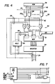
- the error/erasure locator 32 (which determines inter alia coefficients of the error/erasure locator polynomial) is shown in FIG. 2 as including a bank 52 of syndrome registers 52 o -52 n-K-1 ; a convolution circuit 53 including a first bank 54 of PISO (parallel-in, serial out) multipliers 54 o -54 n-K-1 ; a bank 56 of coefficient registers 56 o -56 n-K ; a prior discrepancy generator 58; a SIPO (serial-in, parallel-out) multiplier 60; a second bank 61 of PISO multipliers 611-61 n-K ; a bank 62 of auxillary registers 62 o -62 n-K-1 ; a bank 64 of accumulators 641-64 n-K-1 ; and, a bank 66 of basis converters 661-66 n-K-1 .
- PISO parallel-in, serial out
- the error/erasure locator 32 also includes a first bank 69 of multiplexers 69 o ' 691. . .69 n-K-1 ; a second bank 70 of multiplexers 70 o ' 701, . . . 70 n-K-1 ; multiplexer 72; and, a third bank 74 of multiplexers 74 o , 741, . . .74 n-K-1 .
- Each multiplexer in the first bank is associated with a corresponding one of the syndrome registers in bank 52 to control the selection of input data to the corresponding syndrome register.
- each multiplexer in the second bank 70 is associated with a corresponding one of the coefficient registers in bank 56 to control the selection of input data to the corresponding syndrome register.
- each multiplexer in the third bank 74 is associated with a corresponding one of the auxiliary registers in bank 62 to control the selection of input data to the corresponding auxiliary register.
- each multiplexer included in the error/erasure locator 32 connects the data input port of its associated register with a selected one of a plurality of input options.
- the input options for each multiplexer are alphabetically labelled in FIG. 2 to correspond with similarly referenced enablement signals generated by the timer/controller 39.
- the multiplexers in bank 52 each have input options A, K, and B, which are active upon the generation by timer/controller 39 of the respective signals ENA-A; ENA-K, and ENA-B.
- multiplexer option enablement signals ENA-A through ENA-F and ENA-I through ENA-K are generated by the timer/controller 39.
- the timer/controller is also responsible for generating such signals as a CKA signal (applied to CKA pins of syndrome registers in bank 52); a CKB signal (applied to CKB pins of coefficient registers in bank 56); CKC and CKD signals (applied to pins of the prior discrepancy generator 58); a signal CKE (applied to the CKE pins of the SIPO 60); a signal CKF (applied to CKF pins of the bank 64 of accumulators); a signal CKG (applied to the CKG pins of 62 of auxiliary registers in bank 62); and a signal RST-DNDM-ACC (applied to register 154).
- the syndrome registers in bank 52 are connected in a circular shift path 91.
- the syndrome circular shift path 91 includes a clockwise path 92 (comprising m-bit leads 92 o -92 n-K-1 ) and a counter clockwise path 93 (comprising m-bit leads 93 o -93 n-K-1 ).
- lead 921 connects the data output port of register 52 o to the data input port of register 511 via multiplexer 691
- lead 922 connects the data output port of register 521 to the data input port of register 522 via multiplexer 692, and so forth.
- the data output port of register 52 n-K-1 is connectable by m-bit lead 92R back to the data input port of register 52 o via multiplexer 69 o .
- lead 93 o connects the data output port of register 521 to the data input port of register 52 o via multiplexer 69 o
- lead 93 connects the data output port of register 522 to the data input port of register 521 via multiplexer 691, and so forth.
- the data output ports of the syndrome registers included in bank 52 are also connected by m-bit leads 94 o through 94 n-K-1 , respectively, to respective PISO multipliers 54 o through 54 n-K-1 .
- the m-bit leads 40 o , 401, . . . 40 n-K-1 in bus 40 are connected to data input ports of the syndrome registers 52 o , 521, . . . 52 n-k-1 , respectively, through the respective associated multiplexers 69 o , 691, . . . 69 n-K-1 upon generation of the signal ENA-K.
- the syndrome values are applied in parallel to their corresponding syndrome registers in bank 52.
- lead 40 o is connected to multiplexer 69 o associated with syndrome register 52 o ;
- lead 40 n-k-1 is connected to multiplexer 691 associated with syndrome register 521;
- lead 40 n-K-2 is connected to multiplexer 692 associated with syndrome register 522; and so forth so that lead 401 is connected to multiplexer 69 n-K-1 associated with syndrome register 52 n-K-1 .
- the coefficient registers 56 o -56 n-K-1 included in bank 56 each have their data output ports connectable back to their data input ports by moans of m-bit feedback loops 100 o - 100 n-K-1 when signal ENA-C is generated.
- Each m-bit feedback loop 100 o -100 n-K-1 has a respective multiplier 102 provided thereon.
- the coefficient registers 56 o -56 n-K included in bank 56 each have their data input ports controlled by an associated one of the multiplexers 70 o , 701, . . . 70 n-K-1 .
- the multiplexer 70 governs the choice of signal to be applied to the data input port of the coefficient register.
- the multiplexer 70 o applies to the data input port of the coefficient register 56 o an initilization value ⁇ o on lead 104 when the signal ENA-D is generated and a feedback value from loop 100 o when the signal ENA-C is generated.
- the PISO multipliers in bank 54 are included in a cascading arrangement with the SIPO multiplier 60 and the PISO multipliers in bank 61 to perform three multiplication operations in only two sets of clock cycles.
- the cascading of the PISO multipliers in bank 54 with the SIPO multiplier 60 facilitates the performance of two multiplication operations in just one set of clock cycles.
- the cascading of the PISO multipliers in bank 54 with the SIPO multiplier 60 results in both the generation of the current discrepancy d n and the discrepancy product d n d m ⁇ 1 during a first set of clock cycles of a coefficient iteration.
- FIG. 13 shows a sequential serial-in, parallel-out multiplier comprising an AND gate means 105; an adder 106; a register 107; and a multiplier 108 provided on a feedback loop 109.
- the AND gate means comprises m number of 2-input AND gates.
- the adder 106 comprises m number of 2-input XOR gates.
- One of the inputs, A is applied in parallel and the other input, B, is applied sequentially.
- the register 107 contains the product, C.
- FIG. 15 shows a prallel-in, serial-out multiplier, wherein a register is initially loaded with "A” and the output of the multiplier is "Co” with each clock the next bit of the product is produced.
- Input "A” is in ⁇ representation and input “B” is in ⁇ representation.
- a PISO multiplier followed by a SIPO multiplier can produce the product (AXB)XC in m number of clock pulses.
- FIG. 16 illustrates such a multiplier, it being observed that the parallel input is ⁇ i A instead of A.
- the error erasure locator circuit 32 of the present invention utilizes PISO multipliers similar to FIG. 15 and a SIPO multiplier 60 which resembles the multiplier of FIG. 16 (as derived in the foregoing manner) and cascades the two types of multipliers together to perform two multiplication operations in a single set of clock cycles.
- the convolution circuit (framed by broken line 53) comprises PISO multipliers 54 o - 54 n-K-1 included in bank 54.
- Each PISO multiplier included in the bank 54 includes one of the coefficient registers in bank 56 and its associated feedback loop; one of a plurality of logical AND gate means 110 o -110 n-K-1 ; and, an adder 112 shared in common by each of the PISO multipliers included in bank 54.
- Each feedback loop 100 has a multiplier 102 provided thereon, the structure of the multiplier 102 being understood with reference to FIG. 7 for a particular generator polynomial.
- each logical AND gate means 110 comprises m number of AND gates, each AND gate receiving input bits of the same order from leads 94 and 120.
- the input terminals of the logical AND gate means 110 are connected to the data output port of the associated syndrome register 52 by the m-bit lead 94 and to the data output port of the associated coefficient register by m-bit lead 120.
- Each AND gate means 110 o - 110 n-K-1 has an enablement pin E which receives a signal from the controller/timer 39 when the AND gate is to be activated.
- the output terminals of each logical AND gate means 110 o -110 n-K-1 is connected by an associated m-bit lead 122 o -122 n-K-1 , respectively, to input terminals of the adder 112.
- the adder 112 is a logical exclusive OR (XOR) gate which performs a logical XOR operation with respect to the n-K number of incoming values expressed on the m-bit leads 122 o -122 n-K-1 .
- the output terminal of the adder 112 is connected by a 1-bit line 124 to the SIPO multiplier 60 and by a 1-bit line 126 to the prior discrepancy generator 58.
- convolution circuit 53 functions to multiply the contents of a syndrome register with its paired coefficient register, to obtain a product using the logical AND gate means, and to sum all such products similarly obtained with respect to each register pair using the adder 112.
- the output of the adder 112 is thus the inner product of the contents of the bank 52 of syndrome registers and the bank 56 of coefficient registers, associated ones of the registers having been paired according to related subscripts.
- the output from adder 112 is a bit d ni , which becomes part of a serial bit stream which is known as the current discrepancy (where i indexes from o to m-1).
- the prior discrepancy generator 58 comprises a serial-to-parallel shift register 130; a prior discrepancy determination register 132; and, a read-only memory (ROM) 134 utilized to determine a product d m ⁇ 1 ⁇ i which includes the multiplicative inverse d m ⁇ 1 of the prior discrepancy.
- the shift register 130 receives the serial bit stream format of the current discrepancy d n on 1-bit line 126 and, during successive clock signals, converts this current discrepancy d n from a serial format to a parallel format.
- the m output pins of the shift register 130 are connected by lead 93 n-K-1 to the syndrome register 52 n-K-1 via the multiplexer 69 n-K-1 and by an m-bit lead 136 to the input pins of the prior discrepancy determination register 132.
- Register 132 uses the current discrepancy d n to determine a prior discrepancy d m in accordance with conventional practice.
- the parallel formatted prior discrepancy is transmitted on m-bit lead 138 to the ROM 134.
- the ROM 134 has stored therein a look-up table for obtaining the multiplicative inverse product d m ⁇ 1 ⁇ i of the prior discrepancy.
- the manner in which data is stored in the look-up table of ROM 134 is hereinafter described with reference to FIG. 12.
- An appropriate value in the look-up table is addressable using the prior discrepancy value applied by lead 138 and by an index value i applied on lead 140.
- the ROM 134 is connected to the SIPO multiplier 60 by an m-bit lead or bus 142.
- the SIPO multiplier 60 comprises the ROM 134; logical AND gate means 150; an adder 152; a special register or discrepancy product register 154; and, means 156 for applying the contents of the register 154 to input terminals of the adder 152.
- the logical AND gate means 150 comprises eight AND gates 150A-150H.
- the 1-bit line 124 carrying the current discrepancy d n is connected to first input terminals for each of the AND gates 150A-150H.
- Second input terminals of the AND gates 150A-150H are connected to unique lines included in the m-bit lead 142 carrying multiplicative inverse product d m ⁇ 1 ⁇ i of the prior discrepancy.
- the means 156 for applying the contents of register 154 to input terminals of the adder 152 comprise an m-bit lead which connects the data output port of the register 154 to the adder 152.
- the adder 152 comprises m number of 2-input logical exclusive OR (XOR) gates.
- the multiplexer 72 controls which of a plurality of possible data signals are applied to data input terminals of the discrepancy product register 154.
- the multiplexer 72 can connect the data input terminals of the register 154 either: (1) to the output terminal of adder 152 when signal ENA-F is generated; (2) to a feedback loop 164 when signal ENA-E is generated; or (3) to erasure location bus 42 when signal ENA-G is generated.
- the feedback loop 164 has a multiplier 166 provided thereon whereby, when the multiplexer 72 selects the feedback loop 164, the multiplexer 166 multiplies the contents of register 154 by a field element ⁇ so that the product can be loaded into the register 154.
- the second bank 61 of PISO multipliers includes the n-K PISO multipliers 611, 612, . . . 61 n-K-1 .
- Each PISO multiplier included in bank 61 shares the discrepancy product register 154 together with feedback loop 164 and multiplier 166 provided thereon, and further comprises a respective one of a plurality of logical AND gate means 1701-170 n-K-1 and a respective one of a plurality of adders 1721-172 n-K-1 .
- the strucure of the multiplier 166 is understood from FIG. 7 with reference to one particular generator polynomial.
- An m-bit lead 174 connects the data output port of discrepancy product register 154 to appropriate input terminals of each of the logical AND gate means 1701-170 n-K-1 .
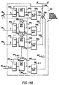
- FIG. 5 shows in detail one such PISO multiplier included in bank 61. From FIG. 5 it is understood that each logical AND gate means comprises m number of AND gates. FIG. 5 also shows the connection of input terminals of the logical AND gate means 170-170 n-K-1 to the m-bit lead 174. The output terminals of each logical AND gate means is connected by lead 182 to the input terminals of its associated adder 172. As also shown in FIG. 5, each of the adders 1721, 1722, . . . 172 n-K-1 comprise a logical exclusive OR (XOR) gate. An output terminal of each adder is connected by a respective one of the lines 1861, 1862,. . . 186 n-K-1 to an associated one of the accumulators 641, 642 . . . 64 n-K-1 , respectively.
- XOR logical exclusive OR
- Each accumulator 641, 642, . . . 64 n-K-1 is a serial-to-parallel shift register having its data output port connected by a respective one of m-bit leads 1881, 1882. . . 188 n-K-1 to input terminals of the respective adders 1721, 1722, . . . 172 n-K-1 .
- the data output ports of the register 641, 642, . . . 64 n-K-1 are connectable under the control of multiplexers 701, 702. . ...70 n-K-1 , respectively, by m-bit leads 1901, 1902, . . . 190 n-K-1 , respectively, to data input ports of the associated coefficient registers 561, 562, . . . 56 n-K-1 .
- the data output ports of the coefficient registers 561, 562, . . . 56 n-K-1 are connected by m-bit leads 1921, 1922, . . . 192 n-K-1 , respectively, to input terminals of associated basis converter circuits 661, 662, . . . 66 n-K-1 .
- the structure of the basis converter circuits 66 is dependent upon the particular generator polynomial employed in the encoding and decoding process. That is, the structure of the basis converter circuits 66 is specially constructed for each generator polynomial to provide the desired results.
- Output terminals of the basis converter circuits 661, 662, . . . 66 n-K-1 are connectable, under the control of multiplexers 741, 742, . . . 74 n-K-1 , during the generation of signal ENA-H, to the data input ports of auxiliary registers 621, 622, . . . 62 n-K-1 , respectively.
- the data input ports of the auxiliary registers 621, 622, . . . 62 n-K-1 are also connectable, under the control of multiplexers 741, 742' . . .
- auxiliary registers 62 o , 621, . . . 62 n-K-2 respectively, during the generation of signal ENA-J, to data output ports of auxiliary registers 62 o , 621, . . . 62 n-K-2 , respectively.
- the data output ports of auxiliary registers 62 o , 621, . . . 62 n-K-1 are connected by m-bit leads 196 o , 1961, . . . 196 n-K-2 , respectively, to the PISO multipliers 611, 612, . . . 61 n-K-1 , respectively, and particularly to the logical AND gates means included in the PISO multipliers.
- auxiliary register 62 n-K-1 is connected by m-bit lead 196 n-K-1 to logical AND gate means 198.
- the output terminal of logical AND gate means 198 is, in turn, connected to the coefficient register 56 n-k .
- each basis converter circuit 66 is required to convert the contents of its associated coefficient register 56 from a second or dual basis representation to a first basis representation. This requirement is imposed by the utilization of PISO multipliers 61, which require a first basis-represented input from auxiliary registers 62 and a second basis-represented input from the product discrepancy register 154.
- FIG. 7 which uses the second basis representation for ⁇ n to produce the ⁇ representation of ⁇ n + 1 , can be used to generate the following table: Element Representation ⁇ o [0 0 0 0 0 1 0 0] ⁇ 1 [0 0 0 0 1 0 0] ⁇ 2 [0 0 0 1 0 0 1] ⁇ 3 [0 0 1 0 0 1 1] ⁇ 4 [0 1 0 0 0 1 1] ⁇ 5 [1 0 0 0 1 1 1 0] ⁇ 6 [0 0 0 1 1 1 0 0] ⁇ 7 [0 0 1 1 1 0 0 0] (It is also observed that FIG. 7 illustrates the structure of the multipliers 102 and 166 when the above-assumed generator polynomial is employed.)
- the erasure location value generator 31 shown in FIG. 9, comprises a linear feedback shift register 220; a FIFO shift register 222; a first AND gate 224; an "up" counter 226; a “down” counter 228; a second AND gate 230; and, an inverter 232.
- the linear feedback shift register 220 includes a register 234 and an associated multiplexer 236.
- the data output port of the register 234 is connected by a feedback loop 238 with multiplier 240 provided thereon to the multiplexer 236.
- the multiplier 234 is configured to multiply the contents of the register 234 by the multiplicative inverse of the field element ⁇ (i.e., by ⁇ ⁇ 1).
- the up counter 226 has its incrementation pin connected to the line 28 which carries the pointer signal.
- the reset pin of up counter 226 is connected to line 29 which carries the signal CODEWORD RST.
- the data output pins of the up counter 226 are connected by lead 242 to the preset data input pins of the down counter 228.
- the load enablement pin of down counter 228 is connected to line 29 which carries the signal CODEWORD RST.
- An output pin 243 of the down counter 228, which when true indicates that the contents of counter 228 is nonzero, is connected by lead 244 to the decrementation pin of down counter 228 and by lead 246 to a first input pin of AND gate 230.
- a second input pin of AND gate 230 is connected to a clock line carrying clock signal CKE.
- the output pin 243 is also connected to lead 248 which carries a signal ENA-G to a counter hereinafter described with reference to FIG. 10 and to the multiplexer 72.
- the AND gate 224 has a first input pin connected to line 28 which carries the pointer signal and to a line which carries the signal SYNGEN CLK.
- the output pin of AND gate 224 is connected to the shift-in pin of FIFO register 222.
- the shift-out pin of FIFO register 222 is connected to the output pin of AND gate 230.
- the data input port of FIFO register 222 is connected by lead 250 to the data output pins of register 234.
- the data output port of FIFO register 222 is connected by the m-bit erasure value location bus 42 to the multiplexer 72 associated with the discrepancy product register 154 of the error/erasure locator circuit 32 of FIG. 2.
- FIG. 9 also shows that the signal CODEWORD RST on line 29 is used to produce an ENA-L signal on line 252 and is inverted by inverter 232 to produce an ENA-M signal on line 254.
- FIG. 10 shows a counter circuit 260 which receives the current discrepancy value d n on lead 261 (from the generator 58); which receives the signal CODEWORD RST on line 29; and which receives the signal ENA-G on line 248 (from the erasure location value generator 31) to produce the signals ENA-H and ENA-J.
- the signals ENA-H and ENA-J are used in determining whether the multiplexers in bank 74 are to apply (to their associated auxiliary registers in bank 62) either the contents of a lower order one of the auxiliary registers or the alpha basis (i.e. first basis) converted contents of an appropriate one of the coefficient registers 56.
- the signal ENA-H is generated whenever a change in the length of the current error locator polynomial occurs.
- the signal ENA-J is generated when signal ENA-H is false.
- Massey Massey (Massey, J. L., "Shift Register Synthesis And BCH Decoding," IEEE Transactions on Information Theory, IT-15, No. 1, pp. 122-123, January, 1969) describes this occurrence as a "change of L,” where L is the length of the current error locator polynomial.
- L is updated when d n ⁇ 0 and 2L ⁇ N where N is the iteration count. When this occurs, L is updated with N+1-L. This requires the use of a counter (for N), a comparator (for 2L ⁇ N ), an adder (for N+1-L) and a register (for L).
- N+ N ⁇ + 1
- L+ L ⁇ + 1
- N ⁇ + 1 - L ⁇ N ⁇ + 1 - L ⁇
- the most significant bit of a negative number is '1' and for zero or positive numbers the MSB is zero.
- the operation of taking the negative of a number and then subtracting '1' can be accomplished simply by taking the complement of the original number.
- the 4-bit 2's complement representation for 3 is 0011.
- the 2's complement representation for -4 is 1100.
- the counter circuit 260 of FIG. 10 includes a register 262; three feedback loops 264, 266, and 268 having inverters 270, 272, and 274, respectively, provided thereon; an AND gate 276; a first OR gate 278; a first inverter 280; second and third OR gates 282 and 284, respectively; and, a second inverter 286.
- the root search and error/erasure magnitude generator 34 includes a divisor generator and error location detector (framed by broken line 300 in FIG. 11); an error pattern dividend generator (framed by broken line 302 in FIG. 11); and, a corrector circuit (framed by broken line 304 in FIG. 11).
- the divisor generator and error location detector 300 shown in FIG. 11 is designed for the case wherein the quantity (n-K) is even.
- the detector 300 includes a n-K number of registers 310.
- Each register has a multiplexer 312 associated therewith and a feedback loop 314 for connecting the data output ports of the registers 310 with the data input port thereof via the associated multiplexers 312.
- Each feedback loop has a multiplier 316 thereon for multiplying the contents of its register 310 by an appropriate power of the field element ⁇ .
- multiplier 3161 multiplies by ⁇ 1 ; multiplier 3162 multiplies by ⁇ 2 ; and so forth.
- the data input terminals of the registers 310 are connectable via their associated multiplexers 312 to appropriate leads in the coefficient bus 44 or to their respective feedback loops 314.
- the leads in the coefficient bus 44 are connected back to appropriate ones of the coefficient registers in bank 56 of FIG. 2.
- leads 441 connect multiplexer 3121 and coefficient register 561; leads 442 connect multiplexer 3122 and coefficient register 562; and so forth.
- the data output ports of the odd registers of the detector 300 are applied to an adder 320.
- Adder 320 performs a logical XOR operation on the applied input values and produces a result, known as the divisor, on m-bit lead 322.
- the data output ports of the even registers of the detector 300 i.e., registers 3102, 3104, 3106 . . .
- the adder 326 performs a logical XOR operation on the contents of the even registers 310, upon the divisor, and upon the field identity element ⁇ o (which is in dual or ⁇ representation) to yield an m-bit output on leads 328.
- Leads 328 are connected to the input pins of an input-inverting AND gate 330.
- the output of the AND gate 330 is applied as an error/erasure locator signal on line 332 to the corrector circuit 304.
- the divisor generator and error location detector 300 evaluates the error/erasure locator polynomial at different roots. When the sum of the contents of all the registers 310 is zero, a root of the polynomial is located and an error location is thus found. For example, if, during a first clock cycle, a zero sum is obtained, an error is known to have occurred in a first byte or symbol of the codeword; if, during a second clock cycle a zero sum is obtained, an error is known to have occurred in a first byte of the codeword; if during a second clock cycle a zero sum is obtained, an error is known to have occurred in the second byte; and so forth.
- the sum of the contents of the registers 310 is obtained by adder 326.
- the error pattern dividend generator 302 includes a quantity (n-K) shift registers 340.
- each register 340 in generator 302 has an associated feedback loop 342 and an associated mulltiplexer 344.
- the feedback loops 3421 through 342 n-K-1 have multiplexers 3461 through 346 n-K-1 , respectively, provided thereon for multiplying the contents of the associated shift register 340 by an appropriate power of the field element ⁇ .
- multiplier 3461 multiplies by ⁇ 1; multiplier 3462 multiplies by ⁇ 2; and so forth.
- the multiplexers 344 are used to connect the data input ports of the registers 340 to either the associated feedback loop 342, or to appropriate leads in the bus 46.
- multiplexer 344 o selectively connects register 340 o to m-bit leads 46 o , which in turn is connected to the syndrome register 52 o of FIG. 2.
- bus 42 serves to transmit the modified syndromes, which are used for obtaining the magnitude of erasures and errors, from the syndrome registers in bank 52 to corresponding registers 340 in the generator 302.
- the data output ports of the registers 340 are applied on m-bit leads to associated m-to-1 multiplexers 348.
- Each multiplexer 348 also receives, on a line 350, an indication i of the current clock cycle in the current clock cycle set.
- the multiplexers 348 use the indication i to determine which bit of their m-bit input is to be multiplexed onto serial output line 352.
- the serial output lines 352 o -352 n-K-1 are connected to an adder 354, which is a logical XOR gate.
- the one-bit output of the XOR operation performed by adder 354 is applied on line 356 to the corrector circuit 304.
- the corrector circuit 304 comprises a ROM 370; a multiplier (framed by broken lines 372 in FIG. 11); and, a basis converter circuit 374.
- the multiplier 372 includes AND gate means 376; an adder 378; a register 380; and, a feedback loop 382 connecting the data output port of the register 380 to input pins of the adder 378.
- the ROM 370 is the same type of memory device as ROM 134 and has the same look-up table stored therein. Values in the look-up table of ROM 370 are addressed using the value of the divisor (on lead 322) and of the current clock cycle or index i of the current clock set. The value obtained from ROM 370 is the product of ⁇ i and the multiplicative inverse of the divisor. This product from ROM 370 is ANDED, at gate means 376 with the dividend value on lead 356 and the error locator signal on line 332.
- the multiplier 372 includes an AND gate means 376 which, although not shown as such, comprises m quantity of AND gates, each of the said AND gates in gate means 376 having three input pins -- a first input pin connected to the error/erasure locator line 332; a second input pin connected to the serial dividend line 356; and, a third input pin connected to a unique one of the lines in the divisor lead 322.
- the adder 378 comprises an XOR gate having m number of input pins connected to output pins of each of the m number of AND gates comprising the AND gate means 376.
- the output of gate 376 is thus non-zero only when a root of the error/erasure polynomial has been located (i.e., when an error or erasure location is detected).
- the output of the AND gate 376 is accumulated over sequential clock cycles in a clock cycles set by virtue of the register 380 and adder 378 to produce an accumulated error pattern which is in the second or ⁇ basis representation.
- the accumulated error pattern in the second basis is then applied to a basis converter circuit 374 so that the accumulated error pattern is converted to a first or ⁇ basis representation.
- the basis convert circuit 374 is, for a given generator polynomial, essentially identical to the structure of the basis converter circuits 66 described hereinbefore.
- FIG. 12 is a flowchart which illustrates how entries generated for the look-up table stored in ROMs 134 and 370.
- Each address in ROM 134 and ROM 370 is the concatenation of a bit index ("i") and an element ("A") of GF (2 m ).
- the bit index i ranges from zero to m-1 (binary representation) and A ranges from ⁇ o to ⁇ 2m - 2 (in ⁇ basis representation).
- the flowchart of FIG. 12 is used to generate (2 m ⁇ log2m) entries for the ROMs 134 and 370.
- multiplication by ⁇ is accomplished by shifting one place from high order bit to low order bit and shifting into the high order position the exclusive OR of bits O, 2, 3 and 4. It can be shown that multiplication by ⁇ ⁇ 1 is accomplished by shifting from low order to high order and shifting into the low order position the exclusive OR of bits 1, 2, 3 and 7.
- Multiplication by ⁇ i is done in the following way: ⁇ i , in ⁇ representation, is the vector with "1" in the i th position and "O" elsewhere.
- a PISO multiplier can be used to produce ⁇ i ⁇ ⁇ by initialising the register with ⁇ i and clocking 8 times to serially produce the product. ⁇ must be in ⁇ representation.
- the decoder 26 of FIG. 1 processes codewords in pipeline fashion during successive codeword cycles. That is, during a first codeword cycle the syndrome generator 30 and erasure generator 31 operate on a first codeword; during a second codeword cycle the error/erasure locator 32 operate on the first codeword while the syndrome generator 30 and the erasure generator 31 operate on a second codeword; during a third codeword cycle the generator 34 operates on the first codeword while the locator 32 operates on the second codeword and while the generator 30 and 31 operate on a third codeword. Thus, three different codewords are simultaneonsly operated on by the decoder 26.
- the channel signal processor 24 applies a CODEWORD RST signal on line 29.
- the signal CODEWORD RST is used to reset the registers 45 of the syndrome generator 30 and the up counter 226 of the erasure location value generator 31.
- the signal CODEWORD RST is also used to load the down counter 228 with the value stored in the up counter 226 at the end of the previous codeword cycle.
- the channel signal processor then applies the received codeword data symbol to the registers 45 of the syndrome generator so that the syndromes S o , S1, . . . S n-K-1 can be generated.
- the syndromes are generated in a manner well known in the prior art.
- the channel signal processor 24 being of a type capable of detecting erasures, also generates, during a codeword cycle, signals associated with erasure pointers.
- the channel signal processor 24 loads the linear feedback shift register 234, upon receipt by multiplexer 236 of signal ENA-L, with an initialization value (in ⁇ basis representation) for tracking bytes in a codeword.
- the tracking initialisation value denoted as ⁇ 2m-2 , is applied on line 242.
- an ENA-M signal is generated and used by multiplexer 236 to connect the data input port of the linear feedback shift register 234 to its feedback loop 238.
- the sequence of location tracker values ⁇ 2m-2 , ⁇ 2m-3 .
- ⁇ o is generated. If the channel signal processor 24 places a true signal on line 28 for any data symbol in a codeword, the then-occurring value in the register 234 is shifted into the FIFO register 222 and the up counter 226 is incremented. Concurrently with the shifting of erasure location values for a current codeword into the FIFO register 222, erasure location values for a previous codeword are shifted out of the FIFO register 222 and onto bus 42 for application to the error/erasure locator 32.
- each codeword cycle comprises (n-K) "coefficient” iterations followed by (n-K) "modified syndrome” iterations.
- Each coefficient iteration requires two sets of m clock cycles or clock pulses; each modified syndrome iteration requires one set of m clock cycles or clock pulses. Completion of all coefficient iterations yields the coefficients of the error/erasure polynomial. Thereafter, completion of the modified syndrome iterations yields modified syndromes usable by the circuit of FIG. 11 for obtaining the magnitude of errors and erasures.
- the signal ENA-K is generated and used by the multiplexers 67 of the error/erasure locator 32 to load syndrome values from the syndrome generator 30 into the error/erasure locator 32.
- the syndrome values S o , S1, . . . S n-K-1 are transmitted from the syndrome generator 30 to the error/erasure locator 32 in a parallel manner on bus 40.
- syndrome S o is transmitted on m-bit lead 40 o in bus 47 to syndrome register 52 o (via multiplexer 69 o ) simultaneously with the transmission of syndrome S1 on lead 401 to syndrome register 52 n-K-1 (via multiplexer 69 n-K-1 ), which is simultaneous with the transmission of syndrome S n-K-1 on lead 40 n-K-1 to register 521, and so forth.
- the simultaneous, parallel transmission of syndrome values to the error/erasure locator 32 thus eliminates prior art shift register interface structure between a syndrome generator circuit and an error locator circuit.
- the error/erasure locator 32 is required to take the erasure location values into consideration in determining the coefficients of the error/erasure polynomial. If, for example, a number q of erasure location values are detected for a codeword, the first q number of coefficient iterations utilize the erasure location values -- the first erasure location value is utilized during the first coefficient iteration; the second erasure location value is utilized during the second coefficient iteration; and so forth.
- the circuit 32 essentially performs two basic operations during the first q coefficient iterations of a codeword cycle.
- the PISO multipliers in bank 54 obtain an inner product to produce a bit of the current discrepancy d n and the SIPO multiplier 60 yields the discrepancy product d n d m ⁇ 1.
- the PISO multipliers in bank 61 multiply an appropriate erasure location value (loaded into register 154) by the contents of the auxiliary registers in bank 62.
- the first operation for finding the current discrepancy also occurs during the first set of clock cycles but, in addition, the discrepancy product d n d m ⁇ 1 is also stored in the discrepancy product register 154.
- the PISO multipliers in bank 61 multiply the discrepancy product d n d m ⁇ 1 in the register 154 by the contents of the auxiliary registers in bank 62.
- the locator 32 operates primarily upon the syndrome value S o in the register 52 o .
- the syndrome value S o is shifted on lead 92 o to syndrome register 521, and the syndrome value S1 is shifted on lead 93 into syndrome register 52 o , so that the locator 32 primarily operates upon the syndrome values S1 and So during the second iteration.
- the contents of the registers in bank 52 are thus shifted rightwardly (clockwise) along the syndrome shift path 92.
- the iteration number for the codeword is the number of syndrome values currently being operated upon, with the order of the active syndrome values increasing with successive iterations.
- four syndrome values (S o , S1, S2, and S3) are operated upon.
- Each AND gate means 110 included in the PISO multiplier bank 54 performs a logical AND operation on the m-bit contents of the syndrome register and the m-bit contents of the coefficient register to which its input terminals are connected.
- the adder 112 performs an exclusive OR (XOR) operation on the outputs from the plurality of AND gate means 110.
- the current discrepancy d n is serially-formatted and, as seen hereinafter, is in second basis representation.
- the first bit of the discrepancy is applied both to the prior discrepancy generator 58 and to the SIPO multiplier 60.
- the serially-formatted current discrepancy is loaded into the shift register 130, whereat a parallel-formatted m-bit value therefor appears at the register 130's output terminals for transmission to the prior discrepancy determination register 132.
- pin CKD of register 132 is pulsed to cause d n to be latched into register 132.
- Register 132 determines a prior discrepancy d m in a conventional manner well known to those skilled in the art.
- the m-bit value d m is applied to the ROM 134, which utilizes an internally-stored look-up table to determine the multiplicative inverse product dm ⁇ 1 ⁇ i of the prior discrepancy.
- the SIPO multiplier 60 multiplies the serial current discrepancy by the m-bit multiplicative inverse quantity d m ⁇ 1 ⁇ i .
- the value ⁇ is loaded into the first coefficient register 56 o .
- the multiplexer 70 o applied the products ⁇ of multiplier 102 o to the coefficient register 56 o .
- the value ⁇ 2 is loaded into the coefficient register 56 o by virtue of the feedback loop 100 o and the multiplexer 70 o .
- the contents of the coefficient register 56 o becomes higher powers of the field element ⁇ .
- the contents of the register 56 o will be ⁇ 3, ⁇ 4, ⁇ 5, ⁇ 6, and ⁇ 7. Accordingly, during those successive clock cycles the multiplied contents of coefficient register 56 o will be utilized for producing new values for d n .
- signal ENA-B is activated so that the contents of the registers comprising bank 52 are shifted clockwise to the next right-most register. That is, the contents of register 52 o is shifted into register 521, the contents of register 52 n-K-1 is shifted into register 52 o , and so forth. Also on the mth clock cycle, register bank 56 is loaded via multiplexer 70 from register bank 64.
- the data input port of the product discrepancy register 154 is connected either to the adder 152 or to the erasure value locator bus 42.
- the register 154 is connected to the adder 152, the discrepancy product d n d m ⁇ 1 in second basis representation is stored in the register 154.
- the register 154 is connected to the bus 42, the erasure locator values are stored in the register 154.
- the register 154 has erasure locator values stored therein the ninth clock cycle.
- q 2
- the first erasure locator value is loaded into the register 154.
- the second erasure locator value is loaded into the register.
- the register 154 has the discrepancy product d n d m ⁇ 1 loaded therein.
- FIG. 9 Before discussing the multiplication of the contents of register 154 using the PISO multipiers in bank 61 as occurs during the second set of clock cycles (i.e., clock cycles m+1 through 2m) of a coefficient iteration, a brief digression regarding FIG. 9 is in order to explain the loading of erasure locator values into the register 154 generally.
- the FIFO register 222 Upon the generation of signal CKE, the FIFO register 222 clocks out an erasure locator value
- the number q of erasure locator values clocked out of FIFO register 222 for a codeword is controlled by down counter 228.
- Down counter 228 enables FIFO register 222 to clock out an erasure locator value as long as decrementation of the down counter 228 not reach zero.
- the first erasure value rather than the product d n d m ⁇ 1 is loaded into the discrepancy product register 154 by virtue of signals ENA-G and CKE.
- the multiplexers in bank 74 were operated to load a field identity element ⁇ o into auxiliary register 62 o and to initialise auxiliary registers 621 - 62 n-K-1 .
- the m-bit contents of each of the auxiliary registers 62 is multiplied by the m-bit contents of register 154 using the PISO multipliers in bank 61.
- only PISO multiplier 61 will operate on a non-zero auxiliary register 62 o .
- a parallel formatted, m-bit representation of the contents of shift register 641 appears at the data output port of register 641 and is applied to m-bit lead 1901 connected to multiplexer 701.
- the contents of register 154 is multiplied by the field element ⁇ by virtue of the operation of multiplier 166 and the product restored therein.
- the result of the multiplication is added to the current contents of shift register 641 by the adders 1721 with a revised m-bit signal appearing on lead 1901.
- the register 154 is cleared using a signal RST__DNDM__ACC generated by the timer/controller 39.
- signals ENA-D and CKB are generated to load the m-bit signals on leads 190 into the respective coefficient registers 561-56 n-K-1 .
- the signal CKG is generated causing the bank 62 of auxiliary registers to either be loaded with values from corresponding ones of the coefficient registers in bank 56 via basis converters 66 (if the signal ENA-H is activated) or be shifted to the right into a higher order auxiliary register (if the signal ENA-J is activated).
- the counter circuit of FIG. 10 is utilized in the determination of whether signal ENA-H or ENA-J is to be generated. If signal ENA-H is generated, pin CKD of the register 132 is also pulsed, causing d n to be latched into prior discrepancy register 137.
- the multiplier 1021 multiplies the contents of the coefficient registers by the field element ⁇ .
- the value W were loaded into register 561
- the multipliers 102 on feedback loops 100 serve to facilitate a multiplication of the contents of their associated coefficient registers 56 in a second or dual basis.
- the PISO multipliers in bank 61 multiply the contents of register 154 (the second erasure value) by the contents of the auxiliary registers 62.
- the PISO multipliers 61 multiply a first basis represented value (in the auxiliary registers 62) by a second or dual basis represented value.
- the shift registers 64 and adders 172 serve to accumulate the serial products generated by successive multiplication operations of their associated PISO multiplier 61. As explained with reference to the first iteration, the shift registers 64 produce m-bit output signals on their respective leads 190. The m-bit signals on leads 190 are applied, at the end of each iteration, to an associated one of the coefficient registers 56.
- the syndrome values in registers 52 are circularly shifted (rightwardly as shown in FIG. 2) so that a higher order syndrome value is loaded into syndrome register 56 o .
- the contents of the register 154 are operated upon in the same manner as earlier described with reference to the first two coefficient iterations of the codeword cycle (e.g., multiplying using the PISO multipliers in bank 61 and accumulating into registers in bank 64). In this manner accumulated values are loaded into the coefficient registers in bank 56.
- the contents of the coefficient registers 56 o - 56 n-K will be the second basis representations of the coefficients of the error locator polynomial for the received codeword.
- the error/erasure locator 32 Upon the completion of (n-K) number of coefficient iterations, the error/erasure locator 32 is capable of generating modified syndromes during (n-K) number of modified syndrome iterations and storing the modified syndromes in the bank 52 of syndrome registers for transmission (on bus 46) to the root search and error/erasure magnitude calculator 34.
- the modified syndromes explained by Gallager, R.G. [ Information Theory and Reliable Communication ; Wiley, New York, 1987] are expressed as follows: where ⁇ j , are error/erasure coefficients and where S i-j are syndrome values.
- the lowest order syndrome value S o is in the highest order syndrome register 52 n-K-1
- syndrome value S1 is in syndrome register 52 n-K-2
- the error/erasure coefficients ⁇ o , ⁇ 1, ⁇ 2.. ⁇ n-K are stored in coefficient registers 56 o , 561, 562, . . . 56 n-K , respectively.
- Each modified syndrome iteration includes m clock cycles. During the m clocks of each modified syndrome iteration, signal ENA-C is activated. As in the coefficient iterations, during the m clock cycles of each modified syndrome iteration the PISO multipliers in bank 54 are used to develop an inner product of paired syndrome registers in bank 52 and coefficient registers in bank 56. Upon the completion of the m clock cycles for a modified syndrome iteration, m serial bits produced by adder 112 are stored in the shift register 130. The contents of shift register 130 is a modified syndrome T i .
- the PISO multiplexers in bank 54 operate in essentially the same manner as in the coefficient iterations, including the successive multiplication of the contents of the coefficient registers in bank 56 by the field element ⁇ .
- all coefficient registers in bank 56 have reloaded therein the coefficient values obtained after the execution of (n-K) number of coefficient iterations.
- the data for reloading is obtained from the associated shift registers in bank 64.
- the error/erasure coefficients ⁇ 1, ⁇ 2,... ⁇ n-K are stored in coefficient registers 561 through 56 n-K and the modified syndromes T n-K-1 , T n-K-2 ,...T o are stored in the syndrome registers 52 o , 521, . . . 52 n-K-1 .
- the error/erasure coefficients are transmitted to the root search and error/erasure magnitude generator 34 on bus 44 (having ((n-K) x m) number of leads) while the modified syndromes are transmitted to the generator 34 on bus 46 (also having ((n-K) x m) number of leads).
- the circuit 300 uses the error/erasure coefficients ⁇ 1, ⁇ 2,... ⁇ n-K both to locate bytes in a codeword at which errors or erasures occur, and to generate a divisor. If the circuit 300 locates an error or erasure for a byte of a codeword, a true signal is applied on line 332 to the corrector circuit 304 while the divisor generated by circuit 300 is applied on m-bit lead 322 to the corrector circuit 304.
- the generator circuit 302 uses the modified syndromes T o , T1, . . . T n-K-1 to produce a serial stream of bits of a dividend.
- the dividend serial bit stream is applied to the corrector circuit 304 by lead 356.
- the correction circuit 304 of FIG. 11 serves to multiply, for bytes at which an error or erasure is located, the error pattern dividend bit stream on line 356 by a divisor-related quantity; to accumulate the product of successive such multiplications; and, to convert the accumulated product from the second basis representation (i.e., ⁇ basis representation) to the first basis representation (i.e., ⁇ basis representation).
- the divisor-related quantity utilized in the multiplication operation performed by corrector circuit 304 is the product of the multiplicative inverse of the divisor (generated by circuit 300 and applied on line 322) and the value ⁇ i .
- the ROM 370 has stored therein essentially the same look-up table as does ROM 134, with values in the table of ROM 370 being addressable using both the divisor value and the current clock cycle number (i.e., "i").
- the multiplier 372 multiplies the dividend serial bit stream on line 356 by the m-bit value extracted from ROM 370 (i.e., the product of ⁇ i and the multiplicative inverse of the divisor). Over the m clock cycles the successive products from multiplier 372 are accumulated in the register 380 is converted by converter circuit 374 from second of ⁇ basis representation to first or ⁇ basis representation.
- the root search and error/erasure magnitude generator of FIG. 11 calculates the error magnitudes E j in accordance with the following: where U j is an error/erasure location (integer from 0 to 2 m -2 where 2 m -2 represents an error in the first codeword symbol and 0 represents an error in the last codeword symbol) and T i is defined as prescribed above.
Landscapes
- Physics & Mathematics (AREA)
- Probability & Statistics with Applications (AREA)
- Engineering & Computer Science (AREA)
- Theoretical Computer Science (AREA)
- Algebra (AREA)
- General Physics & Mathematics (AREA)
- Mathematical Physics (AREA)
- Pure & Applied Mathematics (AREA)
- Error Detection And Correction (AREA)
- Detection And Correction Of Errors (AREA)
Claims (19)
- Fehlerkorrekturvorrichtung zum Dekodieren eines empfangenen Codewortes, wobei die Vorrichtung eine Mehrzahl von Registern (52₀-52n-K-1) zum Speichern von Syndromen des Codewortes, eine Mehrzahl von Koeffizientenregistern (56₀-56n-K-1), in denen Koeffizienten eines Lokalisierpolynoms akkumuliert werden, ein Mittel (53) zum Bearbeiten des Inhalts der Syndromregister und des Inhalts der Koeffizientenregister, um eine gegenwärtige Abweichung zu bestimmen, ein Mittel (60) zum Ermitteln eines Abweichungsprodukts durch Multiplizieren der gegenwärtigen Abweichung mit einem multiplikativen Inversen einer Vorabweichung, ein Mittel (61) zum Multiplizieren des Abweichungsprodukts mit dem Inhalt der Koeffizientenregister und zum Akkumulieren des Produkts in den Koeffizientenregistern aufweist, dadurch gekennzeichnet, daß das Mittel (53) zum Bearbeiten der Syndromregister und der Koeffizientenregister Syndrome, die eine erste Basisdarstellung haben, und Werte in den Koeffizientenregistern, die eine zweite Basisdarstellung haben, bearbeitet,
das Mittel (60) zum Ermitteln des Abweichungsprodukts ein Produkt ermittelt, das eine zweite Basisdarstellung hat,
Mittel (66, 66n-K-1) gebildet sind, um den Inhalt des Koeffizientenregisters von einer zweiten Basisdarstellung in eine erste Basisdarstellung umzuwandeln, und
die Mittel (61₁-61n-K-1) zum Multiplizieren des Abweichungsprodukts solche Produkte mit Werten multipliziert, die zur umgewandelten ersten Basisdarstellung der Koeffizientenregister gehören, um das resultierende Produkt in der zweiten Basisdarstellung in den Koeffizientenregistern zu akkumulieren. - Vorrichtung nach Anspruch 1, wobei das Mittel (61₁-61n-K-1) zum Multiplizieren des Abweichungsprodukts mit Werten, die zur umgewandelten ersten Basisdarstellung der Koeffizientenregister (56₀-56n-K) gehören, die Werte, die zur umgewandelten ersten Basisdarstellung der Koeffizientenregister gehören, mit Löschlokalisierungswerten (αei) mit einer ersten Basisdarstellung multiplizieren kann.
- Vorrichtung nach Anspruch 1, wobei das Mittel (53) zum Bearbeiten des Inhalts der Syndromregister (52₀-52n-K-1) und des Inhalts der Koeffizientenregister (56₀-56n-K) ein inneres Produkt bestimmt unter Verwendung des Inhalts der Syndromregister und des Inhalts der Koeffizientenregister, und wobei das innere Produkt in einem seriellen Format vorliegt.
- Vorrichtung nach Anspruch 1, wobei das Mittel (53) zum Bearbeiten des Inhalts der Syndromregister (52₀-52n-K-1) und des Inhalts der Koeffizientenregister (56₀-56n-K) eine erste Bank (54) einer Mehrzahl von Multiplizierern (54₀-54n-K-1) mit paralleler Eingabe und serieller Ausgabe (PISO-Multiplizierer) aufweist, wobei jeder der PISO-Multiplizierer so gebildet ist, daß er den Inhalt eines Syndromregister (52₀-52n-K-1) in der ersten Basisdarstellung und den Inhalt eines Koeffizientenregisters (56₀-56n-K) in der zweiten Basisdarstellung bearbeitet, um eine gegenwärtige Abweichung in der zweiten Basisdarstellung zu erhalten, und wobei jeder PISO-Multiplizierer:
ein Mittel (102₀-102n-K-1) zum Multiplizieren des Inhalts eines entsprechenden der Koeffizientenregister mit einem Körperelement, ein logisches AND-Gatter-Mittel (110₀-110n-K-1) zum Ausführen einer logischen AND-Operation mit dem Inhalt in zweiter Basisdarstellung des jeweiligen der Koeffizientenregister und dem Inhalt in erster Basisdarstellung eines gepaarten der Syndromregister, um eine Ausgabe zu bilden, und
ein Mittel (112) zum Verwenden der Ausgabe vom AND-Gatter in einer Exklusiv-OR- (XOR-) Operation aufweist. - Vorrichtung nach Anspruch 4, wobei das Mittel zum Multiplizieren des Inhalts eines entsprechenden der Koeffizientenregister mit dem Körperelement
eine Rückkopplungsschleife (100), die einen Ausgangsanschluß des Koeffizientenregisters mit einem Eingangsanschluß von ihm verbindet, ein Multipliziermittel (102), das in der Rückkopplungsschleife enthalten ist, zum Multiplizieren des Inhalts des Koeffizientenregisters mit dem Körperelement, um ein Produkt zu erhalten, und
eine Einrichtung (70) zum Laden des Produkts des Multipliziermittels in das Koeffizientenregister aufweist. - Vorrichtung nach Anspruch 1, wobei die gegenwärtige Abweichung in der zweiten Basisdarstellung mit einem seriellen Format ausgedrückt ist, eine zum multiplikativen Inversen gehörende Größe in der zweiten Basisdarstellung mit einem parallelen Format ausgedrückt ist, und die gegenwärtige Abweichung von einem Multiplizierer (60) mit serieller Eingabe und paralleler Ausgabe (SIPO-Multiplizierer) mit einer Größe multipliziert wird, die zum multiplikativen Inversen gehört, der gebildet ist, um die seriell formatierte gegenwärtige Abweichung mit einer parallel formatierten Größe zu multiplizieren, die zum multiplikativen Inversen gehört, um ein parallel formatiertes Abweichungsprodukt in der zweiten Basisdarstellung zu erhalten.
- Vorrichtung nach Anspruch 6, wobei der SIPO-Multiplizierer (60) eine Mehrzahl von logischen AND-Gattern (150), wobei jedes der AND-Gatter erste Anschlüsse aufweist, die über eine serielle Leitung mit der Faltungsschaltung (53) zum Empfangen der gegenwärtigen Abweichung verbunden sind, jedes der AND-Gatter einen zweiten Anschluß aufweist, der mit einer einzigen Leitung in einem Kabel (142) verbunden ist, das bei der Einrichtung (58) zum Erhalten der Größe beginnt, die zum multiplikativen Inversen gehört, und jedes der AND-Gates einen Ausgangsanschluß hat,
ein logisches Exklusiv-OR- (XOR-) Gatter (152) mit Eingangsanschlüssen, die Eingangsanschlüsse enthalten, mit denen die Ausgangsanschlüsse der AND-Gatter des SIPO-Multiplizierers verbunden sind, wobei auch das XOR-Gatter einen Ausgangsanschluß hat, ein Mittel zum Umwandeln der gegenwärtigen Abweichung von einem seriellen Format in ein paralleles Format,
ein Mittel (134) zum Benutzen der gegenwärtigen Abweichung in einem parallelen Format, um eine Vorabweichung in einem parallelen Format zu bestimmen,
ein Mittel zum Benutzen der Vorabweichung, um die zum multiplikativen Inversen der Vorabweichung gehörende Größe zu erhalten, und zum Ausdrücken der Größe, die zum multiplikativen Inversen der Vorabweichung gehört, in der zweiten Basisdarstellung, aufweist. - Vorrichtung nach Anspruch 1, wobei das Mittel zum Multiplizieren des Abweichungsprodukts mit einem Wert, der zur umgewandelten ersten Basisdarstellung der Koeffizientenregister gehört, eine zweite Bank (61) einer Mehrzahl von Multiplizierern (61₁-61n-K-1) mit paralleler Eingabe und serieller Ausgabe (PISO-Multiplizierer) aufweist, und wobei jeder der PISO-Multiplizierer, die die zweite Bank von PISO-Multiplizierern bilden,
ein Abweichungsproduktregister (154) mit einer Rückkopplungsschleife (164), die einen Ausgangsanschluß von ihm mit seinem Eingangsanschluß verbindet, wobei die Rückkopplungsschleife einen Multiplizierer (166) zum Multiplizieren des Inhalts des Abweichungsproduktregisters mit einem Körperelement enthält, und das Abweichungsproduktregister und die Rückkopplungsschleife gemeinsam für die Mehrzahl von PISO-Multiplizierern, die die zweite Bank von PISO-Multiplizierern bilden, sind,
ein Mittel (170₁-170n-K-1) zum Ausführen einer logischen AND-Operation mit dem Inhalt des Abweichungsproduktregisters und dem umgewandelten Inhalt eines entsprechenden der Koeffizientenregister (56₀-56n-K) und zum Erhalten eines Ergebnisses, und
ein Mittel (172₀-172n-K-1) zum Ausführen einer logischen ExklusivOR-(XOR-) Operation unter Verwendung des Ergebnisses der logischen AND-Operation aufweist. - Vorrichtung nach Anspruch 8, aufweisend eine Mehrzahl von Akkumulatormitteln (64₁-64n-K-1), und dadurch, daß eines der Akkumulatormittel
ein seriell-nach-parallel-Schieberegister (64), das mit dem seriellen Produkt eines entsprechenden der PISO-Multiplizierer, die in der zweiten Bank (61) von PISO-Multiplizierern enthalten sind, ladbar ist, und
ein Mittel (172₀-172n-K-1) zum Ausführen einer logischen ExklusivOR-(XOR-) Operation mit den Ausgangsdaten vom Schieberegister und dem seriellen Produkt vom entsprechenden PISO-Multiplizierer aufweist. - Vorrichtung nach Anspruch 1, aufweisend
ein Mittel zum Multiplizieren des Inhalts von mindestens einem der Syndromregister (52₀-52n-K-1) mit dem Inhalt eines gepaarten der Koeffizientenregister (56₀-56n-K), um einen modifizierten Syndromwert in einer zweiten Basisdarstellung zu erhalten. - Vorrichtung nach Anspruch 1, aufweisend
ein Mittel (300) zum Benutzen des Inhalts der Koeffizientenregister, um Bytes in einem Codewort zu lokalisieren, in dem ein Fehler oder eine Löschung auftritt, und zum Erzeugen eines Divisors, ein Mittel (302) zum Benutzen der modifizierten Syndrome, die in den Syndromregistern gespeichert sind, um einen Fehlermusterdividenden zu erzeugen,
ein Mittel (304) zum Multiplizieren des Divisors mit dem Dividenden, um ein Produkt zu erhalten, und zum Akkumulieren der Produkte aufeinanderfolgender solcher Multiplikationen, und
ein Mittel (374) zum Umwandeln des akkumulierten Produkts von einer zweiten Basisdarstellung in eine erste Basisdarstellung. - Fehlerkorrekturverfahren zum Dekodieren eines empfangenen Codewortes, wobei das Verfahren von dem Typ ist, bei dem eine Mehrzahl von Syndromregistern (52₀-52n-K-1) geladen werden, um Syndrome des Codeworts zu speichern, eine gegenwärtige Abweichung bestimmt wird durch Bearbeiten des Inhalts der Syndromregister und einer Mehrzahl von Koeffizientenregistern (56₀-56n-K), in denen Koeffizienten eines Lokalisierpolynoms akkumuliert werden, ein Abweichungsprodukts durch Multiplizieren der gegenwärtigen Abweichung mit einem multiplikativen Inversen einer Vorabweichung erhalten wird, das Abweichungsprodukt mit dem Inhalt der Koeffizientenregister multipliziert wird, um in den Koeffizientenregistern akkumulierte Produkte zu erhalten, wobei die Verbesserung die Schritte
Bestimmen der gegenwärtigen Abweichung durch Bearbeiten des Inhalts der Syndromregister mit einer ersten Basisdarstellung und der Werte in den Koeffizientenregistern mit einer zweiten Basisdarstellung, Ermitteln eines Abweichungsprodukts mit einer zweiten Basisdarstellung,
Umwandeln des Inhalts der Koeffizientenregister von einer zweiten Basisdarstellung in eine erste Basisdarstellung,
Multiplizieren des Abweichungsprodukts in einer zweiten Basisdarstellung mit Werten, die zur umgewandelten ersten Basisdarstellung der Koeffizientenregister gehört, und
Akkumulieren des resultierenden Produkts in zweiter Basisdarstellung im Koeffizientenregister aufweist. - Verfahren nach Anspruch 12, wobei der Schritt des Erhaltens einer gegenwärtige Abweichung den Schritt
Bestimmen eines inneren Produkts unter Verwendung des Inhalts einer Mehrzahl von Paaren von Koeffizientenregistern und Syndromregistern, aufweist, und wobei das innere Produkt in seriellem Format ist. - Verfahren nach Anspruch 12, wobei Syndromwerte gleichzeitig in entsprechende der Mehrzahl von Syndromregistern geladen werden.
- Verfahren nach Anspruch 12, wobei die gegenwärtige Abweichung mit einem seriellen Format erhalten wird, wobei eine zum multiplikativen Inversen gehörende Größe die Schritte
Umwandeln der gegenwärtigen Abweichung von einem seriellen Format in ein paralleles Format,
Verwenden der gegenwärtige Abweichung in einem parallelen Format, um eine Vorabweichung im parallelen Format zu erhalten, und
Bestimmen der Größe, die zum multiplikativen Inversen der Vorabweichung gehört, und Ausdrücken der Größe in der zweiten Basisdarstellung aufweist. - Verfahren nach Anspruch 12, ferner aufweisend den Schritt Verschieben des Inhalts eines jeden der Syndromregister zu einem benachbarten Syndromregister, wobei die Verschiebung in einer ersten Richtung entlang eines zyklischen Schiebepfads (91) auftritt, der die Syndromregister verbindet.
- Verfahren nach Anspruch 12, wobei der Inhalt von mindestens einem der Syndromregister mit dem Inhalt eines gepaarten der Koeffizientenregister multipliziert wird, nachdem alle Syndrome erhalten worden sind, um einen modifizierten Syndromwert mit einer zweiten Basisdarstellung zu erhalten.
- Verfahren nach Anspruch 17, ferner aufweisend die Schritte Verwenden des Inhalts der Koeffizientenregister, um Bytes in einem Codewort zu lokalisieren, wo ein Fehler oder eine Löschung auftritt, und einen Divisor zu erzeugen,
Verwenden modifizierter Syndrome, die in den Syndromregistern gespeichert sind, um einen Fehlermusterdividenden zu erzeugen, Multiplizieren des Divisors mit dem Dividenden, um ein Produkt zu erhalten, und Akkumulieren der Produkte aufeinanderfolgender solcher Multiplikationen, und
Umwandeln des akkumulierten Produkts von einer zweiten Basisdarstellung in eine erste Basisdarstellung. - Verfahren nach Anspruch 12, wobei die Werte, die zur umgewandelten ersten Basisdarstellung der Koeffizientenregister gehören, mit den Löschlokalisierwerten, die eine zweite Basisdarstellung haben, statt mit dem Abweichungsprodukt multipliziert werden.
Priority Applications (1)
| Application Number | Priority Date | Filing Date | Title |
|---|---|---|---|
| AT88905286T ATE87157T1 (de) | 1987-06-08 | 1988-05-27 | Verfahren und geraet zur fehlerkorrektur. |
Applications Claiming Priority (2)
| Application Number | Priority Date | Filing Date | Title |
|---|---|---|---|
| US59642 | 1987-06-08 | ||
| US07/059,642 US4845713A (en) | 1987-06-08 | 1987-06-08 | Method and apparatus for determining the coefficients of a locator polynomial |
Publications (2)
| Publication Number | Publication Date |
|---|---|
| EP0365555A1 EP0365555A1 (de) | 1990-05-02 |
| EP0365555B1 true EP0365555B1 (de) | 1993-03-17 |
Family
ID=22024289
Family Applications (1)
| Application Number | Title | Priority Date | Filing Date |
|---|---|---|---|
| EP88905286A Expired - Lifetime EP0365555B1 (de) | 1987-06-08 | 1988-05-27 | Verfahren und gerät zur fehlerkorrektur |
Country Status (6)
| Country | Link |
|---|---|
| US (1) | US4845713A (de) |
| EP (1) | EP0365555B1 (de) |
| JP (1) | JPH0831803B2 (de) |
| AT (1) | ATE87157T1 (de) |
| DE (1) | DE3879493T2 (de) |
| WO (1) | WO1988010032A1 (de) |
Families Citing this family (58)
| Publication number | Priority date | Publication date | Assignee | Title |
|---|---|---|---|---|
| US5111463A (en) * | 1989-11-09 | 1992-05-05 | Exabyte Corporation | Error correction method and apparatus |
| US5430739A (en) * | 1990-03-27 | 1995-07-04 | National Science Council | Real-time Reed-Solomon decoder |
| US5440570A (en) * | 1990-03-27 | 1995-08-08 | National Science Council | Real-time binary BCH decoder |
| US5280488A (en) * | 1990-11-08 | 1994-01-18 | Neal Glover | Reed-Solomon code system employing k-bit serial techniques for encoding and burst error trapping |
| US5343481A (en) * | 1991-01-07 | 1994-08-30 | Kraft Clifford H | BCH error-location polynomial decoder |
| EP0496157A3 (de) * | 1991-01-22 | 1992-08-12 | International Business Machines Corporation | Vorrichtung und Verfahren zur Dekodierung von algebraischen linearen Kodes |
| US5414719A (en) * | 1992-04-24 | 1995-05-09 | Sharp Kabushiki Kaisha | Operating circuit for galois field |
| JP3176171B2 (ja) * | 1993-04-21 | 2001-06-11 | キヤノン株式会社 | 誤り訂正方法及びその装置 |
| JPH06314978A (ja) * | 1993-04-28 | 1994-11-08 | Nec Corp | チェン・サーチ回路 |
| US5535225A (en) * | 1993-10-12 | 1996-07-09 | Hughes Aircraft Company | Time domain algebraic encoder/decoder |
| KR950010768B1 (ko) * | 1993-10-20 | 1995-09-22 | 주식회사 Lg전자 | 에러 정정 코드 복호 장치 및 그 방법 |
| JPH09507117A (ja) * | 1993-11-04 | 1997-07-15 | シーラス ロジック,インコーポレイテッド | リードソロモン復号化器 |
| US5483236A (en) * | 1993-12-20 | 1996-01-09 | At&T Corp. | Method and apparatus for a reduced iteration decoder |
| KR970004515B1 (ko) * | 1993-12-29 | 1997-03-28 | 삼성전자 주식회사 | 리드-솔로몬 복호기의 오류위치다항식 연산방법 및 장치 |
| FR2735889B1 (fr) * | 1995-06-22 | 1997-09-05 | Sgs Thomson Microelectronics | Circuit de calcul de syndrome |
| US5701314A (en) | 1995-12-21 | 1997-12-23 | Cirrus Logic, Inc. | On-the-fly error correction using thermal asperity erasure pointers from a sampled amplitude read channel in a magnetic disk drive |
| US5805617A (en) | 1996-02-28 | 1998-09-08 | Daewoo Electronics Co., Ltd. | Apparatus for computing error correction syndromes |
| US5815515A (en) * | 1996-03-28 | 1998-09-29 | Lsi Logic Corporation | Edge metric calculation method and apparatus using permutations |
| US5875199A (en) * | 1996-08-22 | 1999-02-23 | Lsi Logic Corporation | Video device with reed-solomon erasure decoder and method thereof |
| US5812603A (en) * | 1996-08-22 | 1998-09-22 | Lsi Logic Corporation | Digital receiver using a concatenated decoder with error and erasure correction |
| US6308295B1 (en) | 1996-10-08 | 2001-10-23 | Arizona Board Of Regents | Parallel spectral reed-solomon encoder and decoder |
| US5953636A (en) * | 1996-10-30 | 1999-09-14 | Lsi Logic Corporation | Single-chip DBS receiver |
| US5926489A (en) * | 1996-11-22 | 1999-07-20 | Lsi Logic Corporation | Non-equalized digital receiver using block decoding with erasure and error correction |
| US5942003A (en) * | 1996-12-23 | 1999-08-24 | Lsi Logic Corporation | Error burst detector for lowering receiver bit error rate |
| US5939693A (en) * | 1998-02-02 | 1999-08-17 | Motorola Inc. | Polynomial calculator device, and method therefor |
| CN1897512B (zh) * | 1998-02-25 | 2010-08-11 | 松下电器产业株式会社 | 纠错装置 |
| US6092233A (en) * | 1998-03-20 | 2000-07-18 | Adaptec, Inc. | Pipelined Berlekamp-Massey error locator polynomial generating apparatus and method |
| US6192497B1 (en) * | 1998-08-27 | 2001-02-20 | Adaptec, Inc. | Parallel Chien search circuit |
| JP2000124813A (ja) | 1998-10-20 | 2000-04-28 | Texas Instr Japan Ltd | リードソロモン符号化装置およびその方法とリードソロモン復号装置およびその方法 |
| US6263471B1 (en) | 1999-03-05 | 2001-07-17 | Industrial Technology Research Institute | Method and apparatus for decoding an error correction code |
| TW441195B (en) * | 1999-07-16 | 2001-06-16 | Via Tech Inc | Signal decoding method |
| US20080282128A1 (en) * | 1999-08-04 | 2008-11-13 | Super Talent Electronics, Inc. | Method of Error Correction Code on Solid State Disk to Gain Data Security and Higher Performance |
| US6543026B1 (en) | 1999-09-10 | 2003-04-01 | Lsi Logic Corporation | Forward error correction apparatus and methods |
| TW494315B (en) * | 2000-01-12 | 2002-07-11 | Via Tech Inc | Polynomial coefficient generator |
| US6571368B1 (en) * | 2000-02-02 | 2003-05-27 | Macronix International Co., Ltd. | Systolic Reed-Solomon decoder |
| GB2379768B (en) * | 2000-10-25 | 2003-08-20 | Samsung Electronics Co Ltd | Memory device, method of accessing the memory device, and reed-solomon decoder including the memory device |
| KR100370239B1 (ko) | 2000-10-25 | 2003-01-29 | 삼성전자 주식회사 | 고속 블럭 파이프라인 구조의 리드-솔로몬 디코더에적용하기 위한 메모리 장치와 메모리 액세스 방법 및 그메모리 장치를 구비한 리드-솔로몬 디코더 |
| US7047481B2 (en) * | 2001-10-26 | 2006-05-16 | Koninklijke Philips Electronics N.V. | Decoding method and decoder for Reed Solomon code |
| US7032162B1 (en) * | 2002-04-25 | 2006-04-18 | Lattice Semiconductor Corporation | Polynomial expander for generating coefficients of a polynomial from roots of the polynomial |
| AU2002360207A1 (en) * | 2002-12-30 | 2004-07-22 | Optix Networks, Ltd. | An apparatus and method for parallel calculation of an error code syndrome |
| US7587657B2 (en) * | 2005-04-29 | 2009-09-08 | Agere Systems Inc. | Method and apparatus for iterative error-erasure decoding |
| US7900121B2 (en) * | 2005-05-04 | 2011-03-01 | Siemens Enterprise Communications Gmbh & Co. Kg | Method and device for determining indices assigned to correction symbols |
| US7225381B1 (en) | 2005-06-02 | 2007-05-29 | Lehman Thomas F | Error detection and correction method |
| US7661057B2 (en) * | 2006-02-01 | 2010-02-09 | Broadcom Corporation | Clocking Chien searching at different frequency than other Reed-Solomon (RS) ECC decoding functions |
| US20080082896A1 (en) * | 2006-08-25 | 2008-04-03 | Broadcom Corporation | Burst error correction with offset for correction vector based on fire code |
| US8255758B2 (en) * | 2008-01-21 | 2012-08-28 | Apple Inc. | Decoding of error correction code using partial bit inversion |
| US8327242B1 (en) | 2008-04-10 | 2012-12-04 | Apple Inc. | High-performance ECC decoder |
| US8296632B1 (en) * | 2008-06-06 | 2012-10-23 | Mohammad Amin Shokrollahi | Encoding and decoding of generalized Reed-Solomon codes using parallel processing techniques |
| US8286060B2 (en) * | 2008-07-30 | 2012-10-09 | Lsi Corporation | Scheme for erasure locator polynomial calculation in error-and-erasure decoder |
| US8429498B1 (en) | 2009-03-25 | 2013-04-23 | Apple Inc. | Dual ECC decoder |
| US8453038B2 (en) * | 2009-06-30 | 2013-05-28 | Apple Inc. | Chien search using multiple basis representation |
| US8601352B1 (en) | 2009-07-30 | 2013-12-03 | Apple Inc. | Efficient LDPC codes |
| US8875001B1 (en) * | 2011-09-08 | 2014-10-28 | Xilinx, Inc. | Circuitry for parallel decoding of data blocks |
| US10084481B2 (en) | 2014-12-18 | 2018-09-25 | Apple Inc. | GLDPC soft decoding with hard decision inputs |
| JP2016126813A (ja) * | 2015-01-08 | 2016-07-11 | マイクロン テクノロジー, インク. | 半導体装置 |
| US10911235B2 (en) * | 2015-03-31 | 2021-02-02 | Nec Corporation | Method for verifying information |
| US10230399B2 (en) * | 2015-06-18 | 2019-03-12 | Altera Corporation | Circuitry and method for decomposable decoder |
| US10848182B2 (en) | 2018-09-13 | 2020-11-24 | Apple Inc. | Iterative decoding with early termination criterion that permits errors in redundancy part |
Family Cites Families (11)
| Publication number | Priority date | Publication date | Assignee | Title |
|---|---|---|---|---|
| US4162480A (en) * | 1977-01-28 | 1979-07-24 | Cyclotomics, Inc. | Galois field computer |
| US4410989A (en) * | 1980-12-11 | 1983-10-18 | Cyclotomics, Inc. | Bit serial encoder |
| US4494234A (en) * | 1982-12-29 | 1985-01-15 | International Business Machines Corporation | On-the-fly multibyte error correcting system |
| NL8302214A (nl) * | 1983-06-22 | 1985-01-16 | Philips Nv | Dekodeerinrichting voor het dekoderen van kodewoorden die bloksgewijs middels een reed-solomon-code tegen meerdere symboolfouten per blok beschermd zijn, en uitleesinrichting voor optisch uitleesbare opslaglichamen welke uitleesinrichting voorzien is van zo een dekodeerinrichting. |
| US4559625A (en) * | 1983-07-28 | 1985-12-17 | Cyclotomics, Inc. | Interleavers for digital communications |
| US4633470A (en) * | 1983-09-27 | 1986-12-30 | Cyclotomics, Inc. | Error correction for algebraic block codes |
| US4584686A (en) * | 1983-12-22 | 1986-04-22 | Optical Storage International | Reed-Solomon error correction apparatus |
| US4665523A (en) * | 1984-02-15 | 1987-05-12 | Stanford University | Method and means for error detection and correction in high speed data transmission codes |
| NL8400629A (nl) * | 1984-02-29 | 1985-09-16 | Philips Nv | Snelle decodeur voor reed-solomon-codes, welke mede als encodeur te gebruiken is, alsmede opname/reproduktie-apparaat voorzien van zo een encodeur/decodeur. |
| US4649541A (en) * | 1984-11-21 | 1987-03-10 | The United States Of America As Represented By The Administrator Of The National Aeronautics And Space Administration | Reed-Solomon decoder |
| JPS63164624A (ja) * | 1986-12-26 | 1988-07-08 | Canon Inc | シンドロ−ム生成回路 |
-
1987
- 1987-06-08 US US07/059,642 patent/US4845713A/en not_active Expired - Lifetime
-
1988
- 1988-05-27 AT AT88905286T patent/ATE87157T1/de not_active IP Right Cessation
- 1988-05-27 WO PCT/US1988/001696 patent/WO1988010032A1/en not_active Ceased
- 1988-05-27 DE DE8888905286T patent/DE3879493T2/de not_active Expired - Fee Related
- 1988-05-27 EP EP88905286A patent/EP0365555B1/de not_active Expired - Lifetime
- 1988-05-27 JP JP63504929A patent/JPH0831803B2/ja not_active Expired - Fee Related
Also Published As
| Publication number | Publication date |
|---|---|
| DE3879493D1 (de) | 1993-04-22 |
| DE3879493T2 (de) | 1993-08-19 |
| JPH0831803B2 (ja) | 1996-03-27 |
| EP0365555A1 (de) | 1990-05-02 |
| JPH02503851A (ja) | 1990-11-08 |
| ATE87157T1 (de) | 1993-04-15 |
| WO1988010032A1 (en) | 1988-12-15 |
| US4845713A (en) | 1989-07-04 |
Similar Documents
| Publication | Publication Date | Title |
|---|---|---|
| EP0365555B1 (de) | Verfahren und gerät zur fehlerkorrektur | |
| US5107503A (en) | High bandwidth reed-solomon encoding, decoding and error correcting circuit | |
| US5170399A (en) | Reed-Solomon Euclid algorithm decoder having a process configurable Euclid stack | |
| US4873688A (en) | High-speed real-time Reed-Solomon decoder | |
| US4649541A (en) | Reed-Solomon decoder | |
| US4868828A (en) | Architecture for time or transform domain decoding of reed-solomon codes | |
| US5517509A (en) | Decoder for decoding ECC using Euclid's algorithm | |
| EP0154538B1 (de) | Paritäts- und Syndromgenerator zur Fehler-Erkennung und -Korrektur in digitalen Übertragungssystemen | |
| US5467297A (en) | Finite field inversion | |
| US5440570A (en) | Real-time binary BCH decoder | |
| US20030192007A1 (en) | Code-programmable field-programmable architecturally-systolic Reed-Solomon BCH error correction decoder integrated circuit and error correction decoding method | |
| US6571368B1 (en) | Systolic Reed-Solomon decoder | |
| EP0114938A2 (de) | Korrektur von Fehlerbündeln in Datengruppen | |
| US4797848A (en) | Pipelined bit-serial Galois Field multiplier | |
| US5805617A (en) | Apparatus for computing error correction syndromes | |
| US5535225A (en) | Time domain algebraic encoder/decoder | |
| CN1095122C (zh) | 差错定位多项式高速计算电路 | |
| US5396502A (en) | Single-stack implementation of a Reed-Solomon encoder/decoder | |
| US5471485A (en) | Reed-solomon decoder using discrete time delay in power sum computation | |
| US6263471B1 (en) | Method and apparatus for decoding an error correction code | |
| US20040078747A1 (en) | Generalized forney algorithm circuit | |
| KR100258951B1 (ko) | 리드-솔로몬(rs) 복호기와 그 복호방법 | |
| EP0329775B1 (de) | Schaltung mit grosser bandbreite und verfahren zur reed-solomon-kodierung, dekodierung und fehlerkorrektur | |
| US5964826A (en) | Division circuits based on power-sum circuit for finite field GF(2m) | |
| US6691277B1 (en) | High speed pre-computing circuit and method for finding the error-locator polynomial roots in a Reed-Solomon decoder |
Legal Events
| Date | Code | Title | Description |
|---|---|---|---|
| PUAI | Public reference made under article 153(3) epc to a published international application that has entered the european phase |
Free format text: ORIGINAL CODE: 0009012 |
|
| 17P | Request for examination filed |
Effective date: 19891123 |
|
| AK | Designated contracting states |
Kind code of ref document: A1 Designated state(s): AT BE CH DE FR GB IT LI LU NL SE |
|
| 17Q | First examination report despatched |
Effective date: 19920521 |
|
| GRAA | (expected) grant |
Free format text: ORIGINAL CODE: 0009210 |
|
| AK | Designated contracting states |
Kind code of ref document: B1 Designated state(s): AT BE CH DE FR GB IT LI LU NL SE |
|
| PG25 | Lapsed in a contracting state [announced via postgrant information from national office to epo] |
Ref country code: IT Free format text: LAPSE BECAUSE OF FAILURE TO SUBMIT A TRANSLATION OF THE DESCRIPTION OR TO PAY THE FEE WITHIN THE PRESCRIBED TIME-LIMIT;WARNING: LAPSES OF ITALIAN PATENTS WITH EFFECTIVE DATE BEFORE 2007 MAY HAVE OCCURRED AT ANY TIME BEFORE 2007. THE CORRECT EFFECTIVE DATE MAY BE DIFFERENT FROM THE ONE RECORDED. Effective date: 19930317 Ref country code: CH Effective date: 19930317 Ref country code: NL Effective date: 19930317 Ref country code: SE Effective date: 19930317 Ref country code: LI Effective date: 19930317 Ref country code: AT Effective date: 19930317 Ref country code: BE Effective date: 19930317 |
|
| REF | Corresponds to: |
Ref document number: 87157 Country of ref document: AT Date of ref document: 19930415 Kind code of ref document: T |
|
| REF | Corresponds to: |
Ref document number: 3879493 Country of ref document: DE Date of ref document: 19930422 |
|
| PG25 | Lapsed in a contracting state [announced via postgrant information from national office to epo] |
Ref country code: LU Free format text: LAPSE BECAUSE OF NON-PAYMENT OF DUE FEES Effective date: 19930531 |
|
| REG | Reference to a national code |
Ref country code: CH Ref legal event code: PL |
|
| ET | Fr: translation filed | ||
| NLV1 | Nl: lapsed or annulled due to failure to fulfill the requirements of art. 29p and 29m of the patents act | ||
| PLBE | No opposition filed within time limit |
Free format text: ORIGINAL CODE: 0009261 |
|
| STAA | Information on the status of an ep patent application or granted ep patent |
Free format text: STATUS: NO OPPOSITION FILED WITHIN TIME LIMIT |
|
| 26N | No opposition filed | ||
| REG | Reference to a national code |
Ref country code: GB Ref legal event code: IF02 |
|
| PGFP | Annual fee paid to national office [announced via postgrant information from national office to epo] |
Ref country code: FR Payment date: 20020527 Year of fee payment: 15 |
|
| PGFP | Annual fee paid to national office [announced via postgrant information from national office to epo] |
Ref country code: GB Payment date: 20030917 Year of fee payment: 16 |
|
| PGFP | Annual fee paid to national office [announced via postgrant information from national office to epo] |
Ref country code: DE Payment date: 20030918 Year of fee payment: 16 |
|
| PG25 | Lapsed in a contracting state [announced via postgrant information from national office to epo] |
Ref country code: FR Free format text: LAPSE BECAUSE OF NON-PAYMENT OF DUE FEES Effective date: 20040130 |
|
| REG | Reference to a national code |
Ref country code: FR Ref legal event code: ST |
|
| PG25 | Lapsed in a contracting state [announced via postgrant information from national office to epo] |
Ref country code: GB Free format text: LAPSE BECAUSE OF NON-PAYMENT OF DUE FEES Effective date: 20040527 |
|
| PG25 | Lapsed in a contracting state [announced via postgrant information from national office to epo] |
Ref country code: DE Free format text: LAPSE BECAUSE OF NON-PAYMENT OF DUE FEES Effective date: 20041201 |
|
| GBPC | Gb: european patent ceased through non-payment of renewal fee |