EP0365737A1 - Appareil d'examen par radiographie - Google Patents
Appareil d'examen par radiographie Download PDFInfo
- Publication number
- EP0365737A1 EP0365737A1 EP89102330A EP89102330A EP0365737A1 EP 0365737 A1 EP0365737 A1 EP 0365737A1 EP 89102330 A EP89102330 A EP 89102330A EP 89102330 A EP89102330 A EP 89102330A EP 0365737 A1 EP0365737 A1 EP 0365737A1
- Authority
- EP
- European Patent Office
- Prior art keywords
- image recording
- recording system
- patient positioning
- ray examination
- adjustable
- Prior art date
- Legal status (The legal status is an assumption and is not a legal conclusion. Google has not performed a legal analysis and makes no representation as to the accuracy of the status listed.)
- Granted
Links
- 230000000694 effects Effects 0.000 claims description 2
- 238000006073 displacement reaction Methods 0.000 description 2
- 238000000034 method Methods 0.000 description 1
Images

Classifications
-
- A—HUMAN NECESSITIES
- A61—MEDICAL OR VETERINARY SCIENCE; HYGIENE
- A61B—DIAGNOSIS; SURGERY; IDENTIFICATION
- A61B6/00—Apparatus or devices for radiation diagnosis; Apparatus or devices for radiation diagnosis combined with radiation therapy equipment
- A61B6/44—Constructional features of apparatus for radiation diagnosis
- A61B6/4476—Constructional features of apparatus for radiation diagnosis related to motor-assisted motion of the source unit
-
- A—HUMAN NECESSITIES
- A61—MEDICAL OR VETERINARY SCIENCE; HYGIENE
- A61B—DIAGNOSIS; SURGERY; IDENTIFICATION
- A61B6/00—Apparatus or devices for radiation diagnosis; Apparatus or devices for radiation diagnosis combined with radiation therapy equipment
- A61B6/04—Positioning of patients; Tiltable beds or the like
- A61B6/0487—Motor-assisted positioning
-
- A—HUMAN NECESSITIES
- A61—MEDICAL OR VETERINARY SCIENCE; HYGIENE
- A61B—DIAGNOSIS; SURGERY; IDENTIFICATION
- A61B6/00—Apparatus or devices for radiation diagnosis; Apparatus or devices for radiation diagnosis combined with radiation therapy equipment
- A61B6/46—Arrangements for interfacing with the operator or the patient
- A61B6/467—Arrangements for interfacing with the operator or the patient characterised by special input means
- A61B6/469—Arrangements for interfacing with the operator or the patient characterised by special input means for selecting a region of interest [ROI]
Definitions
- the invention relates to an X-ray examination device with an adjustable image recording system and an adjustable patient positioning device.
- An X-ray examination device of this type in which a patient positioning table is supported on one side on a base and can be adjusted in two dimensions and is encompassed by a C-arm, at the ends of which an X-ray emitter and an X-ray image intensifier are attached.
- the patient is adjusted relative to the image recording system by adjusting both the patient positioning table and the image recording system.
- the adjustment processes are not coordinated with each other. This means that the alignment of the patient with respect to the image recording system is carried out by individually adjusting the patient positioning table and the image recording system itself.
- the invention is based on the object of designing an X-ray examination apparatus of the type mentioned at the outset in such a way that the setting of the patient with respect to the image recording system is simplified compared to the prior art and in particular takes place more quickly.
- a control device assigned to the image recording system and the patient positioning device is designed such that when one adjustable component moves in one direction, the other adjustable component moves automatically in the opposite direction.
- a manual adjustment of the patient positioning table and a motorized adjustment of the image recording system both movements being such are coordinated with one another so that when the patient positioning table is displaced in the longitudinal direction, there is an opposite motor displacement of the image recording system, so that a quick adjustment of the patient with respect to the image recording system is ensured in this way.
- a further development of the invention consists in that the entire positioning range of the patient positioning device is subdivided into subregions, to which switching means are assigned which bring about an opposite movement of the image recording system only in predetermined subregions.
- This can e.g. achieved that a central area of the patient positioning device is present in which there is no automatic adjustment of the image recording system in the opposite direction. When this range is exceeded, an opposite adjustment takes place.
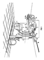
- a C-arm 1 which carries at its ends an X-ray emitter 2 and an X-ray image intensifier 3 with a subsequent single-image camera 4 and a non-visible television camera.
- the C-arm 1 forms together with the components 2, 3, 4 an image recording system and is along it
- the circumference is adjustably mounted on a holder 5, which is pivotally connected to a carriage 7 about a horizontal axis 6.
- the carriage 7 is mounted in a longitudinally displaceable manner on a vertical column 8, which can be moved in a ceiling rail 9 and in a floor rail 10 which run parallel to one another and to the longitudinal direction of a patient support table 11.
- the C-arm 1 grips the patient positioning table 11 transversely.
- the patient support table 11 is mounted on a base 14 with adjustable height, to which a control panel 15 is attached. It is manually adjustable in longitudinal and transverse directions relative to the base 14 (floating storage).
- the adjustment of the patient support table 11 in the longitudinal direction is indicated by the arrows 16, 17.
- the arrows 18, 19 indicate the adjustment of the column 8 in the rails 9, 10.
- the motor 21 is provided in its base 20.
- the motor 21 is controlled by a control device 22, to which an encoder 23 is connected in the handle 23a, which delivers an electrical signal corresponding to the adjustment of the patient support table 11 in the direction of the arrows 16, 17.
- the control device 22 based on the signal from the transmitter 23 via the motor 21, automatically adjusts the column 8 in the opposite direction using the image recording system 1, 2, 3, 4 in the direction of the arrow 19. If the patient positioning table 11 is adjusted in the direction of the arrow 17, the motor 8 automatically moves the column 8 in the opposite direction using the image recording system 1, 2, 3, 4 in the direction of the arrow 18.
- the setting of a patient lying on the patient positioning table 11 in with respect to the image recording system 1, 2, 3, 4 can be done very quickly and easily due to the automatic, opposite adjustment described.
- Fig. 1 only the opposite adjustment of the patient support table 11 and the column 8 with the image recording system 1, 2, 3, 4 is shown in one dimension. However, it is also possible to provide such an opposing adjustment in a second dimension that is perpendicular to the first dimension. If, for example, the patient support table 11 is moved in the direction of the axis 6 in the direction of the column 8, the image recording system 1, 2, 3, 4 can be automatically adjusted in the direction of the axis 6 away from the column 8 and vice versa.
- the holder 5 can be connected to the carriage 7 in a motor-adjustable manner in the direction of axis 6.
- the described automatic, opposing adjustment of the image recording system 1, 2, 3, 4 to the patient positioning table 11 by means of a parallel displacement of the column 8 to the longitudinal direction of the patient positioning table 11 takes place on the basis of the signal supplied by the encoder 23 and corresponding to the direction of movement of the patient positioning table 11.
- FIG. 2 shows that a holder 25 for four parallel guide rods 26, 27, 28, 29 is attached to the accessory rail 24 of the patient support table 11.
- adjustable actuators 30 to 33 are attached, which cooperate with limit switches 34 to 37.
- the image recording system 1, 2, 3, 4 remains at rest, and is therefore not moved in the opposite direction to the patient support table 11. If the central adjustment range of the patient support table 11 is exceeded, the actuation is actuated on one side member 30 the limit switch 34 or on the other side the actuator 33 the limit switch 37. This activates the control device 22. When the central area is exceeded, ie when the limit switches 34 or 37 are actuated, the image recording system 1, 2, 3, 4 is adjusted in opposite directions, namely at a first low speed.
- the actuating element 31 actuates the limit switch 35 or the actuating element 32 the limit switch 36. This increases the speed for the opposite adjustment of the image recording system 1 to 4.
- the entire positioning range of the patient support table 11 is thus divided into five sub-areas (central area, to which two sub-areas are connected on both sides), to which components 30 to 37 are assigned as switching means, which counteract movement of the image recording system 1, 2, 3 , 4 effect only in predetermined sub-areas, namely in the sub-areas lying on both sides outside the central area. All sections can be adjusted by adjusting the actuators 30 to 33 on the guide rods 26 to 29. By evaluating the signals from the limit switches 34 to 37, the control device 22 causes the adjustment speed of the image recording system 1, 2, 3, 4 to be set as a function of the adjustment stroke of the patient support table.
Landscapes
- Health & Medical Sciences (AREA)
- Life Sciences & Earth Sciences (AREA)
- Medical Informatics (AREA)
- Engineering & Computer Science (AREA)
- Radiology & Medical Imaging (AREA)
- Molecular Biology (AREA)
- Biophysics (AREA)
- Nuclear Medicine, Radiotherapy & Molecular Imaging (AREA)
- Optics & Photonics (AREA)
- Pathology (AREA)
- Physics & Mathematics (AREA)
- Biomedical Technology (AREA)
- Heart & Thoracic Surgery (AREA)
- High Energy & Nuclear Physics (AREA)
- Surgery (AREA)
- Animal Behavior & Ethology (AREA)
- General Health & Medical Sciences (AREA)
- Public Health (AREA)
- Veterinary Medicine (AREA)
- Apparatus For Radiation Diagnosis (AREA)
- Radiography Using Non-Light Waves (AREA)
Priority Applications (3)
| Application Number | Priority Date | Filing Date | Title |
|---|---|---|---|
| EP89102330A EP0365737B1 (fr) | 1988-10-25 | 1989-02-10 | Appareil d'examen par radiographie |
| US07/420,914 US5020089A (en) | 1988-10-25 | 1989-10-13 | X-ray examination installation with coordinated positioning of the imaging system and the patient support mechanism |
| JP1989123951U JPH0725921Y2 (ja) | 1988-10-25 | 1989-10-23 | X線診断装置 |
Applications Claiming Priority (3)
| Application Number | Priority Date | Filing Date | Title |
|---|---|---|---|
| EP88117778 | 1988-10-25 | ||
| EP88117778 | 1988-10-25 | ||
| EP89102330A EP0365737B1 (fr) | 1988-10-25 | 1989-02-10 | Appareil d'examen par radiographie |
Publications (2)
| Publication Number | Publication Date |
|---|---|
| EP0365737A1 true EP0365737A1 (fr) | 1990-05-02 |
| EP0365737B1 EP0365737B1 (fr) | 1993-05-12 |
Family
ID=26114600
Family Applications (1)
| Application Number | Title | Priority Date | Filing Date |
|---|---|---|---|
| EP89102330A Expired - Lifetime EP0365737B1 (fr) | 1988-10-25 | 1989-02-10 | Appareil d'examen par radiographie |
Country Status (3)
| Country | Link |
|---|---|
| US (1) | US5020089A (fr) |
| EP (1) | EP0365737B1 (fr) |
| JP (1) | JPH0725921Y2 (fr) |
Cited By (2)
| Publication number | Priority date | Publication date | Assignee | Title |
|---|---|---|---|---|
| EP0463187A1 (fr) * | 1990-06-19 | 1992-01-02 | Siemens Aktiengesellschaft | Appareil à usage médical |
| EP0506172A3 (en) * | 1991-03-25 | 1993-09-01 | N.V. Philips' Gloeilampenfabrieken | X-ray examination apparatus and console system and control console suitable for use in such an x-ray examination apparatus |
Families Citing this family (14)
| Publication number | Priority date | Publication date | Assignee | Title |
|---|---|---|---|---|
| FR2662928B1 (fr) * | 1990-06-06 | 1992-08-28 | Sopha Medical | Procede de basculement avec un osteodensimetre d'un examen anteroposterieur a un examen lateral. |
| NL9200286A (nl) * | 1992-02-17 | 1993-09-16 | Sven Ploem | Botsvrij besturingssysteem voor een meerassig bestuurbare manipulator. |
| US5220592A (en) * | 1992-05-08 | 1993-06-15 | Picker International, Inc. | Diagnostic imaging system with compact multi-function controller |
| DE4322835C2 (de) * | 1993-07-08 | 1997-06-26 | Siemens Ag | Röntgendiagnostikgerät mit einer Transportstellung |
| JP3577114B2 (ja) * | 1994-09-20 | 2004-10-13 | 株式会社東芝 | シンチレーションカメラ |
| US6029081A (en) * | 1998-03-19 | 2000-02-22 | Picker International, Inc. | Movable magnets for magnetic resonance surgery |
| DE19834457A1 (de) | 1998-07-30 | 2000-02-10 | Siemens Ag | Röntgenanordnung |
| US6456684B1 (en) * | 1999-07-23 | 2002-09-24 | Inki Mun | Surgical scanning system and process for use thereof |
| WO2001041647A1 (fr) * | 1999-12-08 | 2001-06-14 | Koninklijke Philips Electronics N.V. | Support pour equipements medicaux a grande latitude de deplacement |
| JP4172753B2 (ja) * | 2002-04-03 | 2008-10-29 | 東芝医用システムエンジニアリング株式会社 | X線画像撮影装置 |
| EP1400828A1 (fr) * | 2002-09-17 | 2004-03-24 | Möller-Wedel GmbH | Microscope d'opération chirurgical |
| WO2007012990A2 (fr) * | 2005-07-25 | 2007-02-01 | Koninklijke Philips Electronics, N.V. | Systeme et procede pour former des images a rayons x laterales et frontales d'un patient |
| JP4810182B2 (ja) * | 2005-10-17 | 2011-11-09 | キヤノン株式会社 | 放射線撮影装置 |
| DE102008063193B4 (de) * | 2008-12-29 | 2011-06-16 | Yxlon International Gmbh | Vorrichtung zur zerstörungsfreien Untersuchung zylindrischer oder rohrförmiger Prüfobjekte mittels Röntgenstrahlung |
Citations (4)
| Publication number | Priority date | Publication date | Assignee | Title |
|---|---|---|---|---|
| FR1539969A (fr) * | 1967-08-11 | 1968-09-20 | Tokyo Shibaura Electric Co | Table d'examen et de thérapie pour la mise en oeuvre de rayonnements |
| DE2356276A1 (de) * | 1972-12-27 | 1974-07-04 | Transform Roentgen Matern Veb | Roentgenuntersuchungsgeraet |
| FR2247954A5 (en) * | 1973-10-15 | 1975-05-09 | Fellus Marcel | Remotely controlled radiographic stand - can perform controlled movement between X-ray source and film support |
| FR2464057A1 (fr) * | 1979-08-31 | 1981-03-06 | Thomson Csf | Appareil de radiodiagnostic a manipulation assistee |
Family Cites Families (2)
| Publication number | Priority date | Publication date | Assignee | Title |
|---|---|---|---|---|
| US2841714A (en) * | 1953-05-11 | 1958-07-01 | Westinghouse Electric Corp | X-ray apparatus |
| US3215835A (en) * | 1963-06-04 | 1965-11-02 | Gen Electric | Selectively engageable power-assist for x-ray table components |
-
1989
- 1989-02-10 EP EP89102330A patent/EP0365737B1/fr not_active Expired - Lifetime
- 1989-10-13 US US07/420,914 patent/US5020089A/en not_active Expired - Fee Related
- 1989-10-23 JP JP1989123951U patent/JPH0725921Y2/ja not_active Expired - Lifetime
Patent Citations (4)
| Publication number | Priority date | Publication date | Assignee | Title |
|---|---|---|---|---|
| FR1539969A (fr) * | 1967-08-11 | 1968-09-20 | Tokyo Shibaura Electric Co | Table d'examen et de thérapie pour la mise en oeuvre de rayonnements |
| DE2356276A1 (de) * | 1972-12-27 | 1974-07-04 | Transform Roentgen Matern Veb | Roentgenuntersuchungsgeraet |
| FR2247954A5 (en) * | 1973-10-15 | 1975-05-09 | Fellus Marcel | Remotely controlled radiographic stand - can perform controlled movement between X-ray source and film support |
| FR2464057A1 (fr) * | 1979-08-31 | 1981-03-06 | Thomson Csf | Appareil de radiodiagnostic a manipulation assistee |
Cited By (3)
| Publication number | Priority date | Publication date | Assignee | Title |
|---|---|---|---|---|
| EP0463187A1 (fr) * | 1990-06-19 | 1992-01-02 | Siemens Aktiengesellschaft | Appareil à usage médical |
| US5159623A (en) * | 1990-06-19 | 1992-10-27 | Siemens Aktiengesellschaft | Medical apparatus with positioning system for a radiation transmitter |
| EP0506172A3 (en) * | 1991-03-25 | 1993-09-01 | N.V. Philips' Gloeilampenfabrieken | X-ray examination apparatus and console system and control console suitable for use in such an x-ray examination apparatus |
Also Published As
| Publication number | Publication date |
|---|---|
| EP0365737B1 (fr) | 1993-05-12 |
| US5020089A (en) | 1991-05-28 |
| JPH0279910U (fr) | 1990-06-20 |
| JPH0725921Y2 (ja) | 1995-06-14 |
Similar Documents
| Publication | Publication Date | Title |
|---|---|---|
| EP0365737B1 (fr) | Appareil d'examen par radiographie | |
| EP0160749A1 (fr) | Appareil pour examen radiologique | |
| CH649238A5 (de) | Tafelzufuehrungseinrichtung an scheren. | |
| EP0180111B1 (fr) | Appareil de commande automatique d'un levier de changement du rapport de transmission | |
| EP0074019A2 (fr) | Pupitre de contrôle | |
| DE3444580C2 (de) | Einrichtung zum Untersuchen der Augen | |
| EP2962674A1 (fr) | Dispositif destiné au réglage en hauteur d'une table d'opération | |
| DE3703783A1 (de) | Vorrichtung zur ausfuehrung einer vertikalbewegung | |
| EP1759446A1 (fr) | Dispositif de bobinage | |
| DE3419765C2 (de) | Einrichtung zur Inspektion von Kernreaktorbrennstäben | |
| DE3218301A1 (de) | Roentgendiagnostikeinrichtung mit einer nachlaufsteuervorrichtung fuer die verstellung der roentgenroehre und des strahlungsempfaengers | |
| EP0245584B1 (fr) | Appareil d'examen à rayon X comprenant un système à rayon X monté sur une colonne | |
| EP0301356B1 (fr) | Distributeur de lumière pour un dispositif de radiodiagnostic | |
| DE3047976C2 (de) | Längsschneidevorrichtung für bewegliche Materialbahnen | |
| DE69406735T2 (de) | Antriebsanordnung für Fahrzeugsitze | |
| EP0923904B1 (fr) | Dispositif pour déplacer une table pour rayons X ou similaire | |
| EP0788767A1 (fr) | Appareil diagnostique à rayons X | |
| EP1611412B1 (fr) | Manipulateur pour dispositif d'essai de matiere non destructif | |
| CH670320A5 (fr) | ||
| DE3126685A1 (de) | "vorrichtung zum abschneiden von profilstraengen, rohren oder dgl." | |
| DE2603167C3 (de) | Verfahren und Vorrichtung zum Ausschneiden der einzelnen Scheiben von gebogenem Mehrscheibensicherheitsglas | |
| EP0132448B1 (fr) | Table à plateau réglable | |
| DE2752145C2 (de) | Vorrichtung zur Erzeugung einer Auflichtanzeige auf einer zu bestückenden Leiterplatte | |
| DE4342016A1 (de) | Vorrichtung zum Verstellen der Höhe und/oder Neigung einer Tischplatte | |
| CH614112A5 (en) | Recording table with apparatus fixing means, in particular for photographic and cinematographic work |
Legal Events
| Date | Code | Title | Description |
|---|---|---|---|
| PUAI | Public reference made under article 153(3) epc to a published international application that has entered the european phase |
Free format text: ORIGINAL CODE: 0009012 |
|
| AK | Designated contracting states |
Kind code of ref document: A1 Designated state(s): BE DE FR GB |
|
| 17P | Request for examination filed |
Effective date: 19900528 |
|
| 17Q | First examination report despatched |
Effective date: 19920513 |
|
| GRAA | (expected) grant |
Free format text: ORIGINAL CODE: 0009210 |
|
| AK | Designated contracting states |
Kind code of ref document: B1 Designated state(s): BE DE FR GB |
|
| REF | Corresponds to: |
Ref document number: 58904335 Country of ref document: DE Date of ref document: 19930617 |
|
| ET | Fr: translation filed | ||
| GBT | Gb: translation of ep patent filed (gb section 77(6)(a)/1977) |
Effective date: 19930809 |
|
| PGFP | Annual fee paid to national office [announced via postgrant information from national office to epo] |
Ref country code: DE Payment date: 19960419 Year of fee payment: 8 |
|
| PGFP | Annual fee paid to national office [announced via postgrant information from national office to epo] |
Ref country code: GB Payment date: 19970123 Year of fee payment: 9 |
|
| PGFP | Annual fee paid to national office [announced via postgrant information from national office to epo] |
Ref country code: BE Payment date: 19970221 Year of fee payment: 9 |
|
| PGFP | Annual fee paid to national office [announced via postgrant information from national office to epo] |
Ref country code: FR Payment date: 19970225 Year of fee payment: 9 |
|
| PG25 | Lapsed in a contracting state [announced via postgrant information from national office to epo] |
Ref country code: DE Effective date: 19971101 |
|
| PG25 | Lapsed in a contracting state [announced via postgrant information from national office to epo] |
Ref country code: GB Free format text: LAPSE BECAUSE OF NON-PAYMENT OF DUE FEES Effective date: 19980210 |
|
| PG25 | Lapsed in a contracting state [announced via postgrant information from national office to epo] |
Ref country code: FR Free format text: THE PATENT HAS BEEN ANNULLED BY A DECISION OF A NATIONAL AUTHORITY Effective date: 19980228 Ref country code: BE Free format text: LAPSE BECAUSE OF NON-PAYMENT OF DUE FEES Effective date: 19980228 |
|
| BERE | Be: lapsed |
Owner name: SIEMENS A.G. Effective date: 19980228 |
|
| GBPC | Gb: european patent ceased through non-payment of renewal fee |
Effective date: 19980210 |
|
| REG | Reference to a national code |
Ref country code: FR Ref legal event code: ST |
|
| PLBE | No opposition filed within time limit |
Free format text: ORIGINAL CODE: 0009261 |
|
| STAA | Information on the status of an ep patent application or granted ep patent |
Free format text: STATUS: NO OPPOSITION FILED WITHIN TIME LIMIT |