EP0365741A2 - Combiné de sécurité - Google Patents
Combiné de sécurité Download PDFInfo
- Publication number
- EP0365741A2 EP0365741A2 EP89108417A EP89108417A EP0365741A2 EP 0365741 A2 EP0365741 A2 EP 0365741A2 EP 89108417 A EP89108417 A EP 89108417A EP 89108417 A EP89108417 A EP 89108417A EP 0365741 A2 EP0365741 A2 EP 0365741A2
- Authority
- EP
- European Patent Office
- Prior art keywords
- handset
- mounting block
- switches
- security device
- switch
- Prior art date
- Legal status (The legal status is an assumption and is not a legal conclusion. Google has not performed a legal analysis and makes no representation as to the accuracy of the status listed.)
- Granted
Links
Images




Classifications
-
- H—ELECTRICITY
- H04—ELECTRIC COMMUNICATION TECHNIQUE
- H04M—TELEPHONIC COMMUNICATION
- H04M1/00—Substation equipment, e.g. for use by subscribers
- H04M1/68—Circuit arrangements for preventing eavesdropping
-
- H—ELECTRICITY
- H04—ELECTRIC COMMUNICATION TECHNIQUE
- H04M—TELEPHONIC COMMUNICATION
- H04M1/00—Substation equipment, e.g. for use by subscribers
- H04M1/02—Constructional features of telephone sets
- H04M1/19—Arrangements of transmitters, receivers, or complete sets to prevent eavesdropping, to attenuate local noise or to prevent undesired transmission; Mouthpieces or receivers specially adapted therefor
Definitions
- This invention relates to secure telephone systems but more particularly to a security device for use with a telephone handset to prevent eavesdropping while the handset is in an on-hook position.
- One of the requirements of secure telephone systems is that eavesdropping or bugging of the telephone be prevented when the telephone handset is in an on-hook position.
- a telephone security device for preventing use of an on-hook telephone for eavesdropping or bugging is disclosed in United States patent No. 3,715,514 which issued to Alan D. Bell.
- a voltage source is connected to the telephone line selector and hook switch through a dialled matrix and sensing relay coil.
- all conductors from the telephone instrument are short circuited together and are disconnected from the telephone conductors leading out of a private or secure area in which the telephone is located.
- the short circuiting is accomplished by a plurality of relays responsive to the condition of the sensing relay.
- the conductors leading from the telephone are connected to the conductors leading from the area for normal conversational use.
- a lamp and photoresistor device is provided to isolate the annunciator from external conductors.
- a first object of the present invention is to provide a security device for use with a telephone handset and which is relatively easy to install and inexpensive to manufacture.
- Another object of the present invention is to provide a security device able to place the telephone handset in either an operative or secure mode depending on the orientation of the telephone handset.
- Yet another object of the present invention is to provide a security device adapted to be placed in a telephone handset and which will short circuit the microphone and ear transducers and disconnect them from the main set when the handset is in the secure mode.
- an aspect of the present invention is to provide a security device for use with a telephone handset having a microphone and an ear transducer, adapted to prevent eavesdropping while the handset is in an on-hook position, comprising: first switching means connected across said ear and microphone transducers; and second switching means connected in series with said ear and microphone transducers, such that when said handset is placed within a first predetermined orientation, corresponding to a secure mode, said first switching means becomes closed, shorting said ear and microphone transducers and said second switching means becomes open, and when said handset is placed within a second predetermined orientation, corresponding to an operating mode, said first switching means becomes open to enable said ear and microphone transducers, and said second switching means becomes closed.
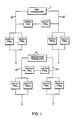
- the security device is basically comprised of a number of position-sensing switches adapted to be disposed in a telephone handset (not shown). Depending on the orientation of the handset, the telephone is either in a secure mode or in an operative mode. As shown in Figure 1, these position-sensing switches are connected to the ear transducer 11 and microphone transducer 12 forming part of a telephone handset (not shown).
- a first pair of position sensing switches PSS1 and PSS2 is connected across ear transducer 11.
- a second pair of position sensing switches PSS7 and PSS8 is connected across microphone transducer 12.
- Each pair is so disposed in the handset, as will be described further, such that each switch is closed when the handset is within the first range of predetermined orientations, corresponding to the secure mode whereas at least one switch in each pair is open when the handset is within a second range of predetermined orientations corresponding to the operating mode.
- a third pair of position sensing switches PSS3 and PSS4 is connected in series with terminal 18 of ear transducer 11.
- a fourth pair of position sensing switches PSS5 and PSS6 is connected in series with terminal 20 of ear transducer 11.
- a fifth pair PSS9 and PSS10 is connected in series with terminal 23 of microphone transducer 12 and a sixth pair PSS11 and PSS12 is connected in series with terminal 24 of microphone transducer 12.
- the third, fourth, fifth and sixth pair of position sensing switches are so disposed in the handset such that each switch is open when the handset is within the first range of predetermined orientations corresponding to the secure mode whereas at least one switch in each pair is closed when the handset is within the second range of predetermined orientation corresponding to the operating mode.
- FIG. 2a we have shown three series of movements which allow the secure device of the handset to change from a secure mode to an operating mode.
- the handset 30 is in a secure mode when the angle the longitudinal axis of the handset makes with the horizontal plane extends between 0 and a first predetermined angle.
- the longitudinal axis of the handset is defined by a phantom line 32 which extends between the ear and microphone ends 33 and 34 respectively, of the handset 30.
- the horizontal plane is defined by line 31. Beyond this first predetermined angle, the handset should change from a secure mode to an operative mode.
- the handset is within the first range of predetermined orientations corresponding to a secure mode, when the angle the lateral axis of the handset makes with the horizontal plane extends between 0 and a second predetermined angle.
- the lateral axis of handset 30 is defined by a line extending perpendicular to the longitudinal axis and parallel to the horizontal plane. In Figure 2b and 2c this lateral axis is illustrated at reference numeral 35. Beyond this second predetermined angle, the handset should change to an operative mode.
- FIGS. 3 to 5 will be used to describe the position-sensing switch mounting block 40 which is adapted to retain each switch in a predetermined position and orientation.
- the mounting block is designed to be installed in the handset.
- the mounting block is generally rectangular and is defined by a top surface 41, a bottom surface 42, a first end 43, a second end 44, a first longitudinal side 45 and a second longitudinal side 46.
- the mounting block is adapted to be installed in the telephone handset 30, see Figures 2a to 2c, with end 43 pointing towards the ear transducer 33 and end 44 pointing towards the microphone transducer 34.
- the top surface should face outwardly away from the transducers, i.e. facing the convex side of the handset.
- the mounting block is provided with a plurality of receptacles a - f and a′ - f′ on each of said first and second longitudinal sides 45 and 46. Each is adapted to receive a position-sensing switch in a predetermined arrangement such that, in the secure mode, the first and second pair of position sensing switches will close to short circuit the ear and microphone transducers 11 and 12 respectively.
- the third, fourth, fifth and sixth pairs of switches will be open to disconnect these transducer from the main set (not shown). In the operating mode, at least one switch of each of the first and second pair will be open to remove the short across the transducers. At least one switch of each of the third, fourth, fifth and sixth pair will be closed to reconnect the transducers to the main set.
- the receptacles are each generally tubular in shape and aligned generally along the same axis on each longitudinal side. Each receptacle slopes downwardly and is directed forwardly towards end 43 of block 40.
- the position-sensing switches are each inserted in a receptacle and interconnected as shown in Figures 3 and 4.
- Each receptacle has a central axis A which makes an angle a (alpha) with the longitudinal axis B of the mounting block. Similarly, central axis A makes an angle ⁇ (Beta) with the lateral axis C of the mounting block.
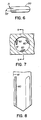
- the mercury switch 50 of Figure 6 can be used as a position-sensing switch.
- the mercury switch should be provided with contact making terminals at one end. This allows the switch to be positioned in the receptacles so as to be either in the open or closed state.
- the switch of Figure 6 is generally tubular and has a first end 51 with a pair of terminals 52.
- the first switch of each pair is inserted in a receptacle on the first longitudinal side of mounting block 40 and the second switch is inserted in a corresponding receptacle on the second longitudinal side of the mounting block.
- the position-sensing switches could be inserted in the mounting block receptacles as follows: PSS1 - a PSS2 - a′ PSS3 - b PSS4 - b′ PSS5 - c PSS6 - c′ PSS7 - d PSS8 - d′ PSS9 - e PSS10 - e′ PSS11 - f PSS12 - f′
- position-sensing switches PSS1, PSS2, PSS7 and PSS8 should all be closed so as to short circuit the ear and microphone transducers 11 and 12 respectively.
- each switch should be inserted in their respective receptacles with their contact making terminals pointing inwardly.
- each pair of the third, fourth, fifth and sixth pair of mercury switches are inserted in their respective receptacles with their contact making terminals pointing outwardly. These will accordingly be open when the handset is in the first predetermined orientation corresponding to the secure mode.
- each mercury switch will change state when the handset is moved within a second predetermined range of orientations. For example switches PSS1, PSS2, PSS7 and PSS8 will change from a closed state to an open one. This being caused by the movement of mercury from one end of the bulb where the contact terminals are located to the other end. Similarly, the remaining mercury switches will change from an open state to a closed state where mercury will flow from one end of the bulb to the opposite end where the contact making terminals are located.
- the mercury switches located closest to the point of rotation will change state.
- the mercury switches on that side of the mounting block i.e. those in receptacles a′ to f′ will change state.
- Mercury will flow from the end of the switch pointing inwardly to the other end pointing outwardly.
- Switches PSS2 and PSS8 will change from a closed state to an open state.
- Switches PSS4, PSS6, PSS10 and PSS12 will change from an open to a closed state.
- each receptacle is provided with a number of flexible ridges 60 secured at one end to the inner wall 61 of the receptacle.
- Each rib extends longitudinally along the length of the receptacle as can be more clearly shown in Figure 8.
- Figure 8 is a sectional view of a receptacle taken along line 8-8 of Figure 7.
- the ribs 60 will flex to allow the bulb to be removably secured therein. This permits the proper positioning of a mercury bulb.
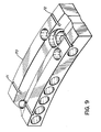
- the mounting block 70 is designed so as to be used with the MERIDIAN (trademark) type business set.
- the mounting block is slightly curved along the longitudinal axis in order to allow easy insertion in the handset.
- a series of grooves 71 and 72 allows the proper lining of leads running from a first mercury switch to another. In particular, these grooves are used for the leads interconnecting mercury switches PSS1 to PSS2 and switches PSS7 to PSS8.
- the angle (alpha) the central axis A makes with the longitudinal axis B of the mounting block is 60°.
- the angle ⁇ (Beta) the central axis A makes with the lateral axis C of the mounting block is 18°.
- the handset will be in the secure mode (all connections from the handset cord to the microphone and ear transducers are open and a short is placed across the ear and microphone transducers) when the handset is laying on a flat table. Lifting the ear end of the handset up while maintaining table contact with the microphone end at any angle less than 9°, the secure mode will be maintained (see Figure 2a).
- the operational mode (all transducers connect to the handset card and all shorts removed) occurs in the range of 9° to 52°. The operational mode is maintained at any angle greater than 52°.
- the secure mode is maintained at angles below 11°.
- the switch from secure to operational mode will occur in the range of 11° to 37°.
- the operational mode is maintained at angles greater than 37°. The same angles for switching will apply for lifting the left side of the handset while holding the right side.
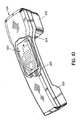
- a switching module 100 is disposed in a typical handset 101 between the receiver and transmitter ends 102 and 103 respectively.
- Electrical leads 104 connect module 100 to the ear transducer (not shown) in receiver end 102.
- Electrical leads 105 are used to connect module 100 to the microphone transducer and the main telephone set through the telephone cord (not shown).
- the microphone transducer is located at the transmitter end 103.
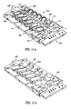
- FIG 11a we have shown a perspective view of the switching module 100. It is basically comprised of switch mounting block 110 disposed on a circuit board 111.
- the switching module 100 is positioned in the handset as is shown in figure 10 with end 119a pointing towards the ear transducer 102 and end 119b pointing towards the microphone transducer 103.
- the circuit board 111 should face outwardly away from the transducers, i.e. facing the convex side of the handset.
- Mounting block 110 is comprised of a number of mercury switch receptacles 113 each disposed on an open face of mounting block 110 in a predetermined orientation. This predetermined orientation is similar to that offered by mounting blocks 40 and 70 of figures 3 and 9.
- the first and last pair of mercury switches 115a, 115b and 116a, 116b have their contact terminals pointing inwardly towards the center of the block whereas the remaining pairs have their contact terminals pointing outwardly.
- Recess 117 and 118 through mounting block 110 allow the terminals of the first and last pair of mercury switches to reach the printed circuit board 111.
- each receptacle 120 has a curvilinear cavity 121 which slopes upwardly inwardly. This inclination is similar to that of mounting block 40 shown in figure 4, i.e. 18° from an horizontal plane. Similarly, the angle the central axis of each receptacle makes with the longitudinal axis of the mounting block is 60°.
- Figure 11c is a bottom view of the module 100 showing the printed circuit board 111.
- the mounting block 110 is positioned on a printed circuit board 111 and secured thereto by means of fasteners 130.
- Board 111 has a circuit pattern 131 formed in a predetermined design to permit contact terminals 114 of each mercury switch to be electrically connected thereto.
- the terminating points 132 generally located in the central region of board 111 are used for soldering contact terminals of the mercury switches. Terminating points 133 are used to connect the module 100 to the ear transducer whereas terminating points 134 are used to connect the module to the microphone transducer (not shown). Terminating points 135 and 136 connect the module to the main set via the telephone cord(not shown).
- the circuit pattern 131 basically represents the block diagram arrangement of figure 1.
- Figure 11d is a partially sectioned view of the support arrangement for the mounting module 100.
- the support is provided by means of a pair of elongated members 140 positioned longitudinally in said handset and a pair of supporting blocks 141 for retaining module 100 within the handset.
- the open rectangular shaped supports 141 are adapted to mate with the rectangular shaped protrusions 122 and 123 shown in figures 11a and 11b. This support arrangement will secure the mounting module in the handset while still permitting easy removal and installation.
Landscapes
- Engineering & Computer Science (AREA)
- Signal Processing (AREA)
- Telephone Set Structure (AREA)
- Telephone Function (AREA)
Applications Claiming Priority (2)
| Application Number | Priority Date | Filing Date | Title |
|---|---|---|---|
| US07/264,992 US4942605A (en) | 1987-12-08 | 1988-10-28 | Security handset |
| US264992 | 1988-10-28 |
Publications (3)
| Publication Number | Publication Date |
|---|---|
| EP0365741A2 true EP0365741A2 (fr) | 1990-05-02 |
| EP0365741A3 EP0365741A3 (fr) | 1991-02-06 |
| EP0365741B1 EP0365741B1 (fr) | 1994-12-14 |
Family
ID=23008504
Family Applications (1)
| Application Number | Title | Priority Date | Filing Date |
|---|---|---|---|
| EP89108417A Expired - Lifetime EP0365741B1 (fr) | 1988-10-28 | 1989-05-10 | Combiné de sécurité |
Country Status (5)
| Country | Link |
|---|---|
| US (1) | US4942605A (fr) |
| EP (1) | EP0365741B1 (fr) |
| JP (1) | JPH0744596B2 (fr) |
| CA (1) | CA1301387C (fr) |
| DE (1) | DE68919995T2 (fr) |
Cited By (2)
| Publication number | Priority date | Publication date | Assignee | Title |
|---|---|---|---|---|
| RU2216875C1 (ru) * | 2003-02-13 | 2003-11-20 | Световидов Владимир Николаевич | Способ защиты абонентского телефонного устройства от несанкционированного акустического контроля |
| RU2632188C1 (ru) * | 2016-12-07 | 2017-10-04 | Федеральное государственное автономное образовательное учреждение высшего образования "Национальный исследовательский университет "Московский институт электронной техники" | Устройство для защиты от несанкционированного прослушивания разговоров в помещении |
Families Citing this family (8)
| Publication number | Priority date | Publication date | Assignee | Title |
|---|---|---|---|---|
| JP3734068B2 (ja) | 1997-11-28 | 2006-01-11 | 株式会社日本コンラックス | 硬貨払出装置 |
| US6411828B1 (en) * | 1999-03-19 | 2002-06-25 | Ericsson Inc. | Communications devices and methods that operate according to communications device orientations determined by reference to gravitational sensors |
| US6549792B1 (en) * | 1999-06-25 | 2003-04-15 | Agere Systems Inc. | Accelerometer influenced communication device |
| AU2003292874A1 (en) * | 2002-12-31 | 2004-07-22 | Zhen Chen | Method and means for preventing the mobile communicate device from interceptor by remote control |
| US9158496B2 (en) | 2012-02-16 | 2015-10-13 | High Sec Labs Ltd. | Secure audio peripheral device |
| US8922372B2 (en) | 2012-07-13 | 2014-12-30 | High Sec Labs Ltd | Secure peripheral connecting device |
| US10194011B2 (en) | 2016-09-27 | 2019-01-29 | High Sec Labs Ltd. | Method and apparatus for securing voice over IP telephone device |
| US11606460B2 (en) * | 2021-04-07 | 2023-03-14 | High Sec Labs Ltd. | Mutual disabling unit for multiple phones |
Family Cites Families (13)
| Publication number | Priority date | Publication date | Assignee | Title |
|---|---|---|---|---|
| BE469339A (fr) * | 1945-04-06 | |||
| US3627930A (en) * | 1969-10-27 | 1971-12-14 | Bell Telephone Labor Inc | Dial-in-handset telephone assembly |
| US3715514A (en) * | 1970-10-07 | 1973-02-06 | Dektor Counterintelligence And | Telephone security device |
| JPS4735811U (fr) * | 1971-05-11 | 1972-12-21 | ||
| AU8205075A (en) * | 1974-06-20 | 1976-12-16 | Warman Int Ltd | Seal assembly for rotating shaft |
| FR2284256A7 (fr) * | 1975-06-26 | 1976-04-02 | Serres Bernard | Perfectionnements aux combines pour postes telephoniques |
| DE2915774C2 (de) * | 1979-04-19 | 1983-08-04 | A. Grothe & Söhne KG, 5000 Köln | Fernsprechgerät und/oder Station einer Gegensprechanlage mit einem Handapparat |
| JPS6052758U (ja) * | 1983-09-20 | 1985-04-13 | 日本電信電話株式会社 | 電話機 |
| US4504701A (en) * | 1983-11-14 | 1985-03-12 | J. C. Penney Company, Inc. | Telephone having circuitry for reducing the audio output of the ringing signal |
| US4675901A (en) * | 1985-05-10 | 1987-06-23 | Geodynamics Corporation | Automatic disconnect device with protected ringer |
| JPS6330055U (fr) * | 1986-08-06 | 1988-02-27 | ||
| US4691336A (en) * | 1986-10-10 | 1987-09-01 | Harris Corporation | Telephone test set having an auxiliary amplifier and speaker for permitting listening to line signals |
| US4837819A (en) * | 1987-12-08 | 1989-06-06 | Northern Telecom Limited | Security handset |
-
1988
- 1988-10-28 US US07/264,992 patent/US4942605A/en not_active Expired - Fee Related
-
1989
- 1989-03-15 CA CA000593869A patent/CA1301387C/fr not_active Expired - Lifetime
- 1989-05-10 DE DE68919995T patent/DE68919995T2/de not_active Expired - Fee Related
- 1989-05-10 EP EP89108417A patent/EP0365741B1/fr not_active Expired - Lifetime
- 1989-06-07 JP JP1143184A patent/JPH0744596B2/ja not_active Expired - Lifetime
Cited By (2)
| Publication number | Priority date | Publication date | Assignee | Title |
|---|---|---|---|---|
| RU2216875C1 (ru) * | 2003-02-13 | 2003-11-20 | Световидов Владимир Николаевич | Способ защиты абонентского телефонного устройства от несанкционированного акустического контроля |
| RU2632188C1 (ru) * | 2016-12-07 | 2017-10-04 | Федеральное государственное автономное образовательное учреждение высшего образования "Национальный исследовательский университет "Московский институт электронной техники" | Устройство для защиты от несанкционированного прослушивания разговоров в помещении |
Also Published As
| Publication number | Publication date |
|---|---|
| EP0365741B1 (fr) | 1994-12-14 |
| US4942605A (en) | 1990-07-17 |
| JPH0744596B2 (ja) | 1995-05-15 |
| CA1301387C (fr) | 1992-05-19 |
| DE68919995D1 (de) | 1995-01-26 |
| EP0365741A3 (fr) | 1991-02-06 |
| JPH02130059A (ja) | 1990-05-18 |
| DE68919995T2 (de) | 1995-05-18 |
Similar Documents
| Publication | Publication Date | Title |
|---|---|---|
| KR100367071B1 (ko) | 무선전화기크래들컨넥터 | |
| US4602842A (en) | Electrical connector receptacle | |
| US5030123A (en) | Connector and patch panel for digital video and data | |
| WO1995032533B1 (fr) | Dispositif modulaire pour appareil d'interface de reseau telephonique | |
| EP0365741B1 (fr) | Combiné de sécurité | |
| EP1608185A3 (fr) | Jack d'interconnexion | |
| AU724934B2 (en) | Auxiliary component connector including microphone channel | |
| GB2344429A (en) | Electrical device and connector | |
| CA2290088A1 (fr) | Connecteur de communication pouvant etre mis a niveau | |
| IE66348B1 (en) | A terminal block for telecommunications | |
| CN101238620B (zh) | 过压保护模块以及至少一个电信模块和至少一个过压模块的组件 | |
| CA1299710C (fr) | Matrice de connexion automatique de lignes de communication | |
| CA2411659A1 (fr) | Borniers et procedes permettant d'etablir et d'interrompre des connections dans un conducteur de telecommunications | |
| CA2091756A1 (fr) | Appareils electriques autonomes | |
| US4286121A (en) | Telephone line cutover apparatus and switch | |
| EP3703197A1 (fr) | Connecteur à fonction de prévention contre la surtension et carte de circuit imprimé le comprenant | |
| CA1289284C (fr) | Combine telephonique a surete | |
| US4620064A (en) | Pocket sized telephone line data communication systems | |
| US6146167A (en) | Telecommunication module having edge mounted jack and switch therefor | |
| US4122313A (en) | Telephone connector cutover block | |
| US5993231A (en) | Electric connector | |
| US5809137A (en) | Telephone liner connector | |
| US5123041A (en) | Apparatus for testing telephone cables | |
| GB2342256A (en) | Portable telephone with hook condition detector | |
| US3513261A (en) | Telephone connector |
Legal Events
| Date | Code | Title | Description |
|---|---|---|---|
| PUAI | Public reference made under article 153(3) epc to a published international application that has entered the european phase |
Free format text: ORIGINAL CODE: 0009012 |
|
| AK | Designated contracting states |
Kind code of ref document: A2 Designated state(s): DE FR GB IT NL SE |
|
| PUAL | Search report despatched |
Free format text: ORIGINAL CODE: 0009013 |
|
| AK | Designated contracting states |
Kind code of ref document: A3 Designated state(s): DE FR GB IT NL SE |
|
| RHK1 | Main classification (correction) |
Ipc: H04M 1/19 |
|
| 17P | Request for examination filed |
Effective date: 19910614 |
|
| 17Q | First examination report despatched |
Effective date: 19930512 |
|
| GRAA | (expected) grant |
Free format text: ORIGINAL CODE: 0009210 |
|
| AK | Designated contracting states |
Kind code of ref document: B1 Designated state(s): DE FR GB IT NL SE |
|
| PG25 | Lapsed in a contracting state [announced via postgrant information from national office to epo] |
Ref country code: IT Free format text: LAPSE BECAUSE OF FAILURE TO SUBMIT A TRANSLATION OF THE DESCRIPTION OR TO PAY THE FEE WITHIN THE PRESCRIBED TIME-LIMIT;WARNING: LAPSES OF ITALIAN PATENTS WITH EFFECTIVE DATE BEFORE 2007 MAY HAVE OCCURRED AT ANY TIME BEFORE 2007. THE CORRECT EFFECTIVE DATE MAY BE DIFFERENT FROM THE ONE RECORDED. Effective date: 19941214 Ref country code: NL Effective date: 19941214 |
|
| REF | Corresponds to: |
Ref document number: 68919995 Country of ref document: DE Date of ref document: 19950126 |
|
| ET | Fr: translation filed | ||
| PG25 | Lapsed in a contracting state [announced via postgrant information from national office to epo] |
Ref country code: SE Effective date: 19950314 |
|
| NLV1 | Nl: lapsed or annulled due to failure to fulfill the requirements of art. 29p and 29m of the patents act | ||
| PLBE | No opposition filed within time limit |
Free format text: ORIGINAL CODE: 0009261 |
|
| STAA | Information on the status of an ep patent application or granted ep patent |
Free format text: STATUS: NO OPPOSITION FILED WITHIN TIME LIMIT |
|
| 26N | No opposition filed | ||
| PGFP | Annual fee paid to national office [announced via postgrant information from national office to epo] |
Ref country code: DE Payment date: 20000508 Year of fee payment: 12 |
|
| PGFP | Annual fee paid to national office [announced via postgrant information from national office to epo] |
Ref country code: FR Payment date: 20000510 Year of fee payment: 12 |
|
| PGFP | Annual fee paid to national office [announced via postgrant information from national office to epo] |
Ref country code: GB Payment date: 20000607 Year of fee payment: 12 |
|
| PG25 | Lapsed in a contracting state [announced via postgrant information from national office to epo] |
Ref country code: GB Free format text: LAPSE BECAUSE OF NON-PAYMENT OF DUE FEES Effective date: 20010510 |
|
| GBPC | Gb: european patent ceased through non-payment of renewal fee |
Effective date: 20010510 |
|
| PG25 | Lapsed in a contracting state [announced via postgrant information from national office to epo] |
Ref country code: FR Free format text: LAPSE BECAUSE OF NON-PAYMENT OF DUE FEES Effective date: 20020131 |
|
| PG25 | Lapsed in a contracting state [announced via postgrant information from national office to epo] |
Ref country code: DE Free format text: LAPSE BECAUSE OF NON-PAYMENT OF DUE FEES Effective date: 20020301 |