EP0365811A1 - Véhicule à garde au sol limitée - Google Patents
Véhicule à garde au sol limitée Download PDFInfo
- Publication number
- EP0365811A1 EP0365811A1 EP89116850A EP89116850A EP0365811A1 EP 0365811 A1 EP0365811 A1 EP 0365811A1 EP 89116850 A EP89116850 A EP 89116850A EP 89116850 A EP89116850 A EP 89116850A EP 0365811 A1 EP0365811 A1 EP 0365811A1
- Authority
- EP
- European Patent Office
- Prior art keywords
- axle
- drive
- belt
- motor
- work vehicle
- Prior art date
- Legal status (The legal status is an assumption and is not a legal conclusion. Google has not performed a legal analysis and makes no representation as to the accuracy of the status listed.)
- Granted
Links
Images


Classifications
-
- A—HUMAN NECESSITIES
- A01—AGRICULTURE; FORESTRY; ANIMAL HUSBANDRY; HUNTING; TRAPPING; FISHING
- A01D—HARVESTING; MOWING
- A01D34/00—Mowers; Mowing apparatus of harvesters
- A01D34/01—Mowers; Mowing apparatus of harvesters characterised by features relating to the type of cutting apparatus
- A01D34/412—Mowers; Mowing apparatus of harvesters characterised by features relating to the type of cutting apparatus having rotating cutters
- A01D34/63—Mowers; Mowing apparatus of harvesters characterised by features relating to the type of cutting apparatus having rotating cutters having cutters rotating about a vertical axis
- A01D34/64—Mowers; Mowing apparatus of harvesters characterised by features relating to the type of cutting apparatus having rotating cutters having cutters rotating about a vertical axis mounted on a vehicle, e.g. a tractor, or drawn by an animal or a vehicle
-
- A—HUMAN NECESSITIES
- A01—AGRICULTURE; FORESTRY; ANIMAL HUSBANDRY; HUNTING; TRAPPING; FISHING
- A01D—HARVESTING; MOWING
- A01D69/00—Driving mechanisms or parts thereof for harvesters or mowers
-
- A—HUMAN NECESSITIES
- A01—AGRICULTURE; FORESTRY; ANIMAL HUSBANDRY; HUNTING; TRAPPING; FISHING
- A01D—HARVESTING; MOWING
- A01D2101/00—Lawn-mowers
Definitions
- the invention relates to a work vehicle with low ground clearance, an engine with a drive shaft which emerges vertically downwards, an axle drive with differential and with a work device following the ground contour, the work tool of which can be driven from the drive shaft via a belt drive running below the axle drive, whereby on the drive shaft underneath the motor and a pulley is provided on an input shaft connected to the work tool and emerging upwards.
- a lawnmower In this known work vehicle in the form of a small tractor, a lawnmower is connected at the rear in such a way that the lawnmower can follow the ground contour, ie the lawnmower constantly changes its position with respect to the pulling small tractor when the ground is uneven.
- the belt drive must follow this change in position, which changes the angular position of the belt drive. When the maximum permissible deflection is reached, the belt is damaged and the drive is interrupted.
- care must also be taken to ensure that the belt does not come into contact with parts of the small tractor, in particular its axle drive.
- Small tractors of this type generally have a very small track width for maneuverability and are built low to prevent tipping, so that their center of gravity is also low and their axle drive comes close to the ground.
- another shaft with two additional pulleys is provided on the axle drive, one pulley via an endless belt with the pulley of the drive shaft on the engine and the other pulley via a second endless belt with the pulley of the input shaft on the work tool of the Ar beits mars is connected to establish a drive connection from the small tractor to the lawn mower.
- Such a solution is of course extremely complex.
- the object to be achieved with the invention is seen in increasing the evasive movement up and down in a belt-driven implement following the ground contour and connected to a work vehicle with low ground clearance with simple means.
- This object has been achieved according to the invention in that the two pulleys are connected to one another by a single belt and the axle drive is designed such that the belt does not come into contact with the axle drive when the implement is raised to the maximum.
- the differential of the axle drive is moved laterally from the area of the belt such that the axle drive is relatively thin in the area of the belt, so that additional space here for the belt that may move upwards when the floor is uneven.
- the axle drive can be provided with a reduction gear arranged at a distance from the differential and can be made relatively thin between the differential and the reduction gear, a hydraulic motor being connected directly or indirectly to the differential, arranged in the axle drive and connected to a hydraulic pump which is connected by the their connected motor is driven.
- a camshaft unit can be provided in the engine for driving the hydraulic pump, the camshaft unit having a shaft with a double gearwheel, one of which meshes with a toothing on the drive shaft and the other ring gear with a toothing on an input shaft of the hydraulic pump.
- the hydraulic motor with reduction gear is further arranged at one end of the axle drive and the differential at the other end of the axle drive, the motor and axle drive being formed as a structural unit and the hydraulic pump on the lower area of the engine is connected in the immediate vicinity of the axle drive.
- a work vehicle 10 of known construction is shown in the form of a small tractor with an implement connected at the rear, which is driven in a conventional manner.
- the work vehicle 10 has a steering wheel 11 and a driver seat 13.
- the connected implement is a lawn mower and is labeled 16. It is attached to the work vehicle via control arms 17 and 18.
- a drive unit 20 of the work vehicle is provided with a motor 21 which is located between two front wheels 22 and / or between two rear wheels 24.
- a known axle drive 26 is arranged between the rear wheels 24 in front of the implement and is driven by the motor 21.
- a belt drive 28 serves this purpose.
- a reduction gear, not shown, and a differential, also not shown, are accommodated side by side, as is apparent from Japanese Patent Publication No. 56-23 065.
- Via a V-belt 32 the force is transmitted from a pulley 33, which is provided at the end of a drive shaft 34 of the motor 21, to a second pulley 36, which is seated on an intermediate shaft 38, which in turn is known to the axle gear 26 is connected.
- Via second V-belt 40 the force is transmitted from a third pulley 41, which is arranged above the pulley 36 on the intermediate shaft 38, to a fourth pulley 42, which is arranged on an input shaft 43 for the working tool of the implement 16.
- the intermediate shaft 38 with the two pulleys 36 and 41 is required in order to bridge the distance between the drive shaft 34 and the input shaft 43 and, at the same time, to ensure that the implement can follow them in the event of unevenness in the floor, the implement or the lawn mower is adjusted up or down compared to the pulling small tractor.
- the second V-belt 40 is also adjusted, i. H. it changes its angular position, but this is only possible within certain limits when transmitting a drive torque (+/- 5 to 8 °). If these limits are exceeded, the belt can no longer transmit power and there is a risk of damage. Given the small distance between the two pulleys 36 and 42 and thus the short belt length, the upward or downward evasive movement is also limited.
- the intermediate shaft 38 can also not be moved further forward, which would result in a longer belt length, because then the V-belt 40 would come to rest against the relatively thick and deep-lying central part 30 of the axle drive 26 for reasons of stability if there was an evasive movement.
- the invention provides a remedy here, whereby, as can be seen from FIG. 1, the lawn mower can be attached to the front or, as can be seen from FIG. 3, also from the rear.
- the work vehicle is designated 50 in detail in FIG. 1. It has a driver's station 52 with a driver's seat 54 and a steering wheel 56.
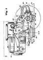
- a working device 58 is mounted on the front via connecting parts 60, and the small tractor is provided with a motor-axle gear combination, which is shown in FIGS. 4 to 6.
- This combination can be designed as a uniform design, but at least the individual housing parts should be connected to one another.
- the front wheels 64 are driven via the axle drive and in the work vehicle according to FIG. 3 the rear wheels are driven via the axle drive.
- a motor 70 and an axle drive 72 can be arranged below the driver's station 52.
- the implement 58 can be driven via a single belt 74, which is driven by a drive shaft 76 of the motor 70, a clearance 80 must be provided in the area of the axle drive 72 so that the Belt 74, which connects the drive shaft 76 to an input shaft 86 on the implement, does not come to bear against the axle drive.
- This free space 80 should be dimensioned such that the implement 58 can move sufficiently high in the event of unevenness in the floor without the belt 74 coming into contact with the underside of the axle drive 72 during the power transmission. In order to achieve this, as can be seen from FIGS.
- the motor-axle drive combination 90 is designed in such a way that the drive shaft 76 of the motor 70 comes as close as possible to the axle center line 92 of the axle drive, as a result of which a pulley 94 located on it in the immediate vicinity of an axle housing 82 for the axle drive 72 can be arranged. This position largely prevents possible contact of the belt with a lower part 96 of the axle housing 82.
- the motor 70 has also moved very close to the axle gear 72 and is also connected to it in order to set the center of gravity of the work vehicle relatively low, with a sufficient distance between the pulley 94 resting on the drive shaft 76 and the floor 98 (see FIG. 1) is retained.
- the clearance for the belt 74 guided beneath the axle drive is achieved, inter alia, by moving a differential 100 provided in the axle housing 82 from the center to the side, preferably to the right side of the work vehicle 50, into the area of the associated wheel to be driven. If the work vehicle is also driven by a hydraulic motor 104, this must also be arranged in the axle housing 82, on the side remote from the differential 100, preferably in the region of the left wheel to be driven.
- a reduction gear 108 is also provided in the axle housing 82 immediately next to the hydraulic motor 104.
- the precise location of the hydraulic motor 104, differential 100 and reduction gear 108 in the axle housing 82 is variable according to requirements, and additional units can also be accommodated in the axle housing 82. However, it should always be noted that there is sufficient space 80 for the belt 74.
- the implement is shown as if it is working on a level floor.
- the belt 74 is essentially straight. However, as soon as work is carried out on uneven ground, the implement 58 and the belt 74 driving its work tool will move up or down.
- the belt becomes an angular position ingest, which, according to the specifications of most belt manufacturers, must not exceed 5 ° in order to be able to transmit a force. This means that the maximum evasive movement of the implement upwards or downwards depends on the distance between the two pulleys on the engine or on the implement, and the greater the distance, the greater the evasive movement upwards or downwards if the 5 ° is maintained.
- the free space 80 must be provided on the drive shaft 76 between its lower part 96 and the belt 74, so that the belt 74 does not strike the underside of the axle housing 82 during an evasive movement upwards.
- This free space in turn is made possible by the special arrangement of the components, such as differential and reduction gear, in the axle housing 82.
- the assignment of a hydraulic pump 112 to the sump of the motor and the liquid flow from the motor sump to the hydraulic pump, the hydraulic motor and back to the hydraulic pump are also important, in particular if the leakage liquid for lubricating the differential and / or the reduction gear should be used. If this is done, the oil must be returned to the sump of the engine after lubrication.
- the axle housing 82 is tubular, connected to the motor and provided with at least one part 83 which at least partially encapsulates the motor.
- 5 shows how the hydraulic motor 104 is installed in the axle housing 82, specifically with the reduction gear 108, the differential 100 and the drive axles.
- the hydraulic motor 104 has a hollow axle carrier 114 which is rotatably received at its two ends in a ball bearing 118 or in a needle bearing 120.
- a slices like shaped cylinder block 122 is slidably engaged by keyways which are arranged on the outer surface of the axle beam.
- a plurality of pistons 124 are provided in a conical surface of the cylinder block 122 with the same angular distance.
- a pressure plate 126 receives pressure from the pistons 124 which are rotatably disposed in the axle housing 82 so that the pressure plate can rotate in one direction of rotation for forward travel and in one direction of rotation for reverse travel.
- An eccentric ring-shaped bushing 127 is formed on one end of the axle carrier 114, and the cylinder block 122 is also used as a brake drum, which is why a brake band 128 is guided around it.
- the hydraulic pump 112 is connected to the engine 70 and is driven by a camshaft unit 130 which is arranged in the engine housing and is driven by the drive shaft 76.
- the hydraulic pump 112 itself is arranged on the outside of the engine 70, and as a result of its drive via the camshaft unit 130 provided in the engine, the engine can be connected to the axle drive 72 at a location which is substantially closer to the ground than before. This feature is particularly important because it lowers the center of gravity, thereby improving stability and reducing the length of the drive shaft 76 or crankshaft, which extends downward as seen from the bottom of the engine, along with the pulley 94 a clutch 95 and still has a sufficient ground clearance.
- the vertical distance that the single belt 74 has from the lower part 96 of the axle housing 82 has also been reduced, so that the evasive movement in the amount of the connected work device has been correspondingly enlarged in the event of unevenness in the floor, without there being the risk that the belt 74 comes to rest against the underside of the axle drive.
- FIG. 5 also shows that the hydraulic pump 112 is preferably to be connected to the lower left side of the motor 70 and, as shown in FIG. 4, is connected to the hydraulic motor 104 via lines 160 and 162, the supply and reflux is reversible depending on whether to drive forward or backward. Further details of this configuration can be found in U.S. Patent Application No. 161,026 dated February 26, 1988, which is incorporated by reference.
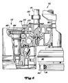
- FIG. 6 shows the camshaft unit 130, via which the crankshaft of the engine 70 or the drive shaft 76 drives an input shaft 113 of the hydraulic pump 112.
- a camshaft 131 is equipped with a double gear 170 and is arranged parallel to the drive shaft 76 and the input shaft 113 and in the middle between these two shafts.
- the double gear has two wheel parts 172 and 174, each having a ring gear 176 and 178, the ring gear 176 with a toothing 180 on the drive shaft 76 and the other toothing 178 with a toothing 182 on a gearwheel 184, which seated on the input shaft 113 in a rotationally fixed manner.
- the camshaft unit 130 is arranged together with the camshaft 131 and the double gear 170 in the engine housing.
- the motor 70 can be lowered by the selected type of drive of the hydraulic pump 112, so that there is an improved center of gravity.
- the reduction gear 108 is designed as a planetary gear.
- Planet gears 132 mesh with the outer periphery of the bushing 127 of the axle carrier 114 and with the internal toothing of a ring gear 134 which is fixedly connected to the axle housing. Keyways are machined in the inner periphery of the hub parts of the planet gears 132.
- the differential 100 is equipped with a hollow housing 136 which is rotatably arranged on one side of the axle housing via ball bearings 138.
- the housing 136 is also provided with an end shaft 140 and receives two rotatably mounted small bevel gears 142 which mesh with a pair of large bevel gears 144 which are rotatably supported in the housing 136 and on the end shaft 140.
- Keyways 146 are machined into an end portion of the end shaft 140 and are connected to the keyways of the planet gears 132 via a connector 150.
- the drive shaft also has a long axle shaft 152 and a short axle shaft 154, the long axle shaft 152 being connected at one end to the inner periphery of one of the large bevel gears 144, with the other end protruding from the axle housing 82 and otherwise through the axle bracket 114 and the connector 150 is guided.
- the other end of the long axle shaft is supported by the needle bearing 120 and the ball bearing 118.
- the short axle shaft 154 is connected via a spline connection to the inner periphery of the other large bevel gear 144, is supported by ball bearings and is led out of the axle housing with its other end.
- the drive wheels are connected to the parts of the axle shafts protruding from the axle housing.
- the diameter of the axle housing 82 is reduced as much as possible, the central part not obstructing the rotation of the planet gears.
- the center line x - x of the axle housing is arranged above the center line of the axis y - y. The resulting free space creates sufficient space for the belt 74, which connects the motor 70 to the connected implement 58, which can deflect sufficiently high in the event of uneven floors without the drive being interrupted.
- the liquid flowing through it also reaches the differential 100 as leakage oil and is returned to the hydraulic pump 112 via a return line 190.
- the diameter of the part above the differential was reduced as much as possible.
- the liquid is cooled via cooling fins, not shown, in the part above the differential.
- liquid will pass from the hydraulic pump 112 to the hydraulic motor 104 and rotation of the cylinder block 122 causes the bushing 127 of the axle bracket 114 to rotate at the same speed.
- the planet gears 132 run on the ring gear 134 and rotate in the opposite direction of rotation about their axes and reduce the speed.
- the rotation of the planet gears is transmitted to the end shaft 140 via the connector 150, whereby the housing 136 and ultimately the axle shafts 154 and 156 are driven.
- the differential works in a known manner, ie drives the wheels at the same speed when driving straight ahead and at correspondingly different speeds when cornering.
- the drive shaft 76 can drive both the front and rear wheels. In both cases, the engine crankshaft drives the implement input shaft 86 via the single belt and two pulleys.
- the intermediate shaft with its two pulleys and a second belt can therefore be dispensed with. This results in an inexpensive device with a greater possibility of evasion upwards or downwards and a relatively low center of gravity.
Landscapes
- Life Sciences & Earth Sciences (AREA)
- Environmental Sciences (AREA)
- Harvester Elements (AREA)
- Arrangement Or Mounting Of Propulsion Units For Vehicles (AREA)
- Agricultural Machines (AREA)
- Arrangement Of Transmissions (AREA)
- Motor Power Transmission Devices (AREA)
Applications Claiming Priority (2)
| Application Number | Priority Date | Filing Date | Title |
|---|---|---|---|
| US24612188A | 1988-09-16 | 1988-09-16 | |
| US246121 | 1988-09-16 |
Publications (2)
| Publication Number | Publication Date |
|---|---|
| EP0365811A1 true EP0365811A1 (fr) | 1990-05-02 |
| EP0365811B1 EP0365811B1 (fr) | 1993-08-04 |
Family
ID=22929388
Family Applications (1)
| Application Number | Title | Priority Date | Filing Date |
|---|---|---|---|
| EP19890116850 Expired - Lifetime EP0365811B1 (fr) | 1988-09-16 | 1989-09-12 | Véhicule à garde au sol limitée |
Country Status (6)
| Country | Link |
|---|---|
| EP (1) | EP0365811B1 (fr) |
| JP (1) | JPH0716336B2 (fr) |
| AU (1) | AU621654B2 (fr) |
| CA (1) | CA1320852C (fr) |
| DE (1) | DE58905140D1 (fr) |
| DK (1) | DK457089A (fr) |
Cited By (2)
| Publication number | Priority date | Publication date | Assignee | Title |
|---|---|---|---|---|
| FR2740001A1 (fr) * | 1995-10-24 | 1997-04-25 | Techni Ind | Tondeuse auto portee |
| EP2139309A4 (fr) * | 2007-04-26 | 2012-05-09 | Ggp Sweden Ab | Dispositif de poulie à courroie et tracteur de jardin le comportant |
Families Citing this family (1)
| Publication number | Priority date | Publication date | Assignee | Title |
|---|---|---|---|---|
| DE102009038185A1 (de) | 2009-08-20 | 2011-02-24 | GM Global Technology Operations, Inc., Detroit | Kraftfahrzeug mit Windschutzscheibe, separater Dachscheibe und ausziehbarem Rollo |
Citations (5)
| Publication number | Priority date | Publication date | Assignee | Title |
|---|---|---|---|---|
| FR1383102A (fr) * | 1963-11-13 | 1964-12-24 | Tondeuse à gazon automotrice à avance hydraulique | |
| US3466855A (en) * | 1966-05-23 | 1969-09-16 | Yard Man Inc | Riding lawn mower |
| FR2190072A5 (fr) * | 1972-06-21 | 1974-01-25 | Agrostroj Prostejov Np | |
| GB2013073A (en) * | 1978-01-25 | 1979-08-08 | Procomas Srl | Remotely controlled mower |
| FR2472336A1 (fr) * | 1979-12-27 | 1981-07-03 | Rover Mowers Pty Ltd | Tondeuse a gazon autopropulsee a lames articulees |
Family Cites Families (5)
| Publication number | Priority date | Publication date | Assignee | Title |
|---|---|---|---|---|
| AU518201B2 (en) * | 1977-11-04 | 1981-09-17 | Rover Mowers (Aust) Pty. Limited | Self propelled flail mower clutch and brake |
| US4232569A (en) * | 1977-11-07 | 1980-11-11 | The J. B. Foote Foundry Co. | Transaxle |
| JPS60154916A (ja) * | 1984-01-21 | 1985-08-14 | Kubota Ltd | 農用トラクタ−における車輪用伝動部の構造 |
| JPH0249063Y2 (fr) * | 1985-08-20 | 1990-12-25 | ||
| JPH0313373Y2 (fr) * | 1985-08-20 | 1991-03-27 |
-
1989
- 1989-07-27 CA CA 606828 patent/CA1320852C/fr not_active Expired - Fee Related
- 1989-08-30 AU AU40919/89A patent/AU621654B2/en not_active Ceased
- 1989-09-12 DE DE8989116850T patent/DE58905140D1/de not_active Expired - Fee Related
- 1989-09-12 EP EP19890116850 patent/EP0365811B1/fr not_active Expired - Lifetime
- 1989-09-14 JP JP1239563A patent/JPH0716336B2/ja not_active Expired - Fee Related
- 1989-09-15 DK DK457089A patent/DK457089A/da not_active Application Discontinuation
Patent Citations (5)
| Publication number | Priority date | Publication date | Assignee | Title |
|---|---|---|---|---|
| FR1383102A (fr) * | 1963-11-13 | 1964-12-24 | Tondeuse à gazon automotrice à avance hydraulique | |
| US3466855A (en) * | 1966-05-23 | 1969-09-16 | Yard Man Inc | Riding lawn mower |
| FR2190072A5 (fr) * | 1972-06-21 | 1974-01-25 | Agrostroj Prostejov Np | |
| GB2013073A (en) * | 1978-01-25 | 1979-08-08 | Procomas Srl | Remotely controlled mower |
| FR2472336A1 (fr) * | 1979-12-27 | 1981-07-03 | Rover Mowers Pty Ltd | Tondeuse a gazon autopropulsee a lames articulees |
Cited By (2)
| Publication number | Priority date | Publication date | Assignee | Title |
|---|---|---|---|---|
| FR2740001A1 (fr) * | 1995-10-24 | 1997-04-25 | Techni Ind | Tondeuse auto portee |
| EP2139309A4 (fr) * | 2007-04-26 | 2012-05-09 | Ggp Sweden Ab | Dispositif de poulie à courroie et tracteur de jardin le comportant |
Also Published As
| Publication number | Publication date |
|---|---|
| AU4091989A (en) | 1990-03-22 |
| JPH02128620A (ja) | 1990-05-17 |
| AU621654B2 (en) | 1992-03-19 |
| DE58905140D1 (de) | 1993-09-09 |
| JPH0716336B2 (ja) | 1995-03-01 |
| CA1320852C (fr) | 1993-08-03 |
| DK457089A (da) | 1990-03-17 |
| EP0365811B1 (fr) | 1993-08-04 |
| DK457089D0 (da) | 1989-09-15 |
Similar Documents
| Publication | Publication Date | Title |
|---|---|---|
| DE60102761T2 (de) | Hydrostatisches Getriebe und Antriebsstrang für ein Kraftfahrzeug | |
| DE69611208T2 (de) | Lenkeinrichtung für ein Fahrzeug mit stufenlosem Getriebe | |
| DE4429093B4 (de) | Getriebe für ein Arbeitsfahrzeug | |
| DE69906436T2 (de) | Integriertes Leistungsverteilungsgetriebe für Traktoren mit Allradantrieb | |
| DE102014009461B4 (de) | Schmieranordnung für eine antriebsachse eines transport-fahrzeuges | |
| DE4307616A1 (de) | Antrieb mit zwei Hydromotoren | |
| WO2008011943A1 (fr) | Boîte de vitesses | |
| DE69714360T2 (de) | Stufenlos schaltendes Lenksystem | |
| DE10214731A1 (de) | Rad-Arbeitsfahrzeug | |
| DE2722266A1 (de) | Gleiskettenfahrzeug | |
| DE3710560C2 (fr) | ||
| DE2350171A1 (de) | Drehmomentverteilergetriebe | |
| DE60033637T2 (de) | Integriertes hydromechanisches achsgetriebe zum antreiben und lenken eines fahrzeuges | |
| DE3506346A1 (de) | Kraftuebertragungsvorrichtung fuer arbeitsfahrzeuge | |
| DE2422779C3 (de) | Antriebsblock für Kraftfahrzeuge | |
| DE69838437T2 (de) | Antriebsvorrichtung zur geschwindigkeitsänderung und lenkung eines fahrzeuges | |
| DE4439118C2 (de) | Antriebsvorrichtung für ein Motorarbeitsfahrzeug | |
| DE19747695C2 (de) | Toroidales Getriebe | |
| EP1634756B1 (fr) | Ensemble d'entraînement | |
| DE4216703B4 (de) | Getriebeanordnung für ein Fahrzeug | |
| DE2335629B2 (de) | Hydrostatisch-mechanischer antrieb fuer land- und bauwirtschaftlich genutzte fahrzeuge | |
| DE69810379T2 (de) | Kraftübertragungseinrichtung für eine Arbeitsmachine | |
| DE60314797T2 (de) | Getriebe für Förderfahrzeug | |
| EP0365811B1 (fr) | Véhicule à garde au sol limitée | |
| DE112004001951T5 (de) | Achsinnenschmiervorrichtung |
Legal Events
| Date | Code | Title | Description |
|---|---|---|---|
| PUAI | Public reference made under article 153(3) epc to a published international application that has entered the european phase |
Free format text: ORIGINAL CODE: 0009012 |
|
| AK | Designated contracting states |
Kind code of ref document: A1 Designated state(s): DE FR GB SE |
|
| 17P | Request for examination filed |
Effective date: 19901001 |
|
| 17Q | First examination report despatched |
Effective date: 19910912 |
|
| GRAA | (expected) grant |
Free format text: ORIGINAL CODE: 0009210 |
|
| AK | Designated contracting states |
Kind code of ref document: B1 Designated state(s): DE FR GB SE |
|
| GBT | Gb: translation of ep patent filed (gb section 77(6)(a)/1977) |
Effective date: 19930806 |
|
| REF | Corresponds to: |
Ref document number: 58905140 Country of ref document: DE Date of ref document: 19930909 |
|
| ET | Fr: translation filed | ||
| PLBE | No opposition filed within time limit |
Free format text: ORIGINAL CODE: 0009261 |
|
| STAA | Information on the status of an ep patent application or granted ep patent |
Free format text: STATUS: NO OPPOSITION FILED WITHIN TIME LIMIT |
|
| 26N | No opposition filed | ||
| EAL | Se: european patent in force in sweden |
Ref document number: 89116850.2 |
|
| PGFP | Annual fee paid to national office [announced via postgrant information from national office to epo] |
Ref country code: GB Payment date: 20010823 Year of fee payment: 13 |
|
| PGFP | Annual fee paid to national office [announced via postgrant information from national office to epo] |
Ref country code: SE Payment date: 20010924 Year of fee payment: 13 Ref country code: FR Payment date: 20010924 Year of fee payment: 13 |
|
| PGFP | Annual fee paid to national office [announced via postgrant information from national office to epo] |
Ref country code: DE Payment date: 20011018 Year of fee payment: 13 |
|
| REG | Reference to a national code |
Ref country code: GB Ref legal event code: IF02 |
|
| PG25 | Lapsed in a contracting state [announced via postgrant information from national office to epo] |
Ref country code: GB Free format text: LAPSE BECAUSE OF NON-PAYMENT OF DUE FEES Effective date: 20020912 |
|
| PG25 | Lapsed in a contracting state [announced via postgrant information from national office to epo] |
Ref country code: SE Free format text: LAPSE BECAUSE OF NON-PAYMENT OF DUE FEES Effective date: 20020913 |
|
| PG25 | Lapsed in a contracting state [announced via postgrant information from national office to epo] |
Ref country code: DE Free format text: LAPSE BECAUSE OF NON-PAYMENT OF DUE FEES Effective date: 20030401 |
|
| GBPC | Gb: european patent ceased through non-payment of renewal fee |
Effective date: 20020912 |
|
| EUG | Se: european patent has lapsed | ||
| PG25 | Lapsed in a contracting state [announced via postgrant information from national office to epo] |
Ref country code: FR Free format text: LAPSE BECAUSE OF NON-PAYMENT OF DUE FEES Effective date: 20030603 |
|
| REG | Reference to a national code |
Ref country code: FR Ref legal event code: ST |