EP0365828B1 - Support pour récipients d'échantillons - Google Patents
Support pour récipients d'échantillons Download PDFInfo
- Publication number
- EP0365828B1 EP0365828B1 EP89117451A EP89117451A EP0365828B1 EP 0365828 B1 EP0365828 B1 EP 0365828B1 EP 89117451 A EP89117451 A EP 89117451A EP 89117451 A EP89117451 A EP 89117451A EP 0365828 B1 EP0365828 B1 EP 0365828B1
- Authority
- EP
- European Patent Office
- Prior art keywords
- holders
- holder
- sample
- members
- sample containers
- Prior art date
- Legal status (The legal status is an assumption and is not a legal conclusion. Google has not performed a legal analysis and makes no representation as to the accuracy of the status listed.)
- Expired - Lifetime
Links
- 229920003023 plastic Polymers 0.000 claims abstract description 14
- 239000004033 plastic Substances 0.000 claims abstract description 14
- 238000012360 testing method Methods 0.000 claims abstract description 5
- 230000004308 accommodation Effects 0.000 claims abstract 8
- 239000000463 material Substances 0.000 claims 6
- 238000007373 indentation Methods 0.000 claims 2
- 238000003780 insertion Methods 0.000 claims 1
- 230000037431 insertion Effects 0.000 claims 1
- 238000003018 immunoassay Methods 0.000 abstract description 11
- 238000005259 measurement Methods 0.000 abstract description 10
- 238000001514 detection method Methods 0.000 abstract description 4
- 239000000523 sample Substances 0.000 description 85
- 238000000034 method Methods 0.000 description 10
- 239000000126 substance Substances 0.000 description 8
- 239000003153 chemical reaction reagent Substances 0.000 description 7
- 230000008719 thickening Effects 0.000 description 7
- 238000013461 design Methods 0.000 description 5
- 239000006249 magnetic particle Substances 0.000 description 5
- 239000012491 analyte Substances 0.000 description 4
- 239000000427 antigen Substances 0.000 description 4
- 102000036639 antigens Human genes 0.000 description 4
- 108091007433 antigens Proteins 0.000 description 4
- 230000005291 magnetic effect Effects 0.000 description 4
- 210000002966 serum Anatomy 0.000 description 4
- 239000000725 suspension Substances 0.000 description 4
- 210000002105 tongue Anatomy 0.000 description 4
- 239000007788 liquid Substances 0.000 description 3
- 239000013610 patient sample Substances 0.000 description 3
- 238000000926 separation method Methods 0.000 description 3
- 238000005406 washing Methods 0.000 description 3
- 238000006243 chemical reaction Methods 0.000 description 2
- 239000011248 coating agent Substances 0.000 description 2
- 238000000576 coating method Methods 0.000 description 2
- 230000000694 effects Effects 0.000 description 2
- 239000002245 particle Substances 0.000 description 2
- 230000002285 radioactive effect Effects 0.000 description 2
- 210000004369 blood Anatomy 0.000 description 1
- 239000008280 blood Substances 0.000 description 1
- 210000000601 blood cell Anatomy 0.000 description 1
- 238000005119 centrifugation Methods 0.000 description 1
- 238000004140 cleaning Methods 0.000 description 1
- 238000010908 decantation Methods 0.000 description 1
- 239000011521 glass Substances 0.000 description 1
- 238000011534 incubation Methods 0.000 description 1
- 230000000977 initiatory effect Effects 0.000 description 1
- 238000002372 labelling Methods 0.000 description 1
- 238000000691 measurement method Methods 0.000 description 1
- 230000005298 paramagnetic effect Effects 0.000 description 1
- 238000002360 preparation method Methods 0.000 description 1
- 238000012545 processing Methods 0.000 description 1
- 230000007704 transition Effects 0.000 description 1
- 238000012795 verification Methods 0.000 description 1
Images

Classifications
-
- B—PERFORMING OPERATIONS; TRANSPORTING
- B01—PHYSICAL OR CHEMICAL PROCESSES OR APPARATUS IN GENERAL
- B01L—CHEMICAL OR PHYSICAL LABORATORY APPARATUS FOR GENERAL USE
- B01L9/00—Supporting devices; Holding devices
- B01L9/06—Test-tube stands; Test-tube holders
-
- Y—GENERAL TAGGING OF NEW TECHNOLOGICAL DEVELOPMENTS; GENERAL TAGGING OF CROSS-SECTIONAL TECHNOLOGIES SPANNING OVER SEVERAL SECTIONS OF THE IPC; TECHNICAL SUBJECTS COVERED BY FORMER USPC CROSS-REFERENCE ART COLLECTIONS [XRACs] AND DIGESTS
- Y10—TECHNICAL SUBJECTS COVERED BY FORMER USPC
- Y10S—TECHNICAL SUBJECTS COVERED BY FORMER USPC CROSS-REFERENCE ART COLLECTIONS [XRACs] AND DIGESTS
- Y10S435/00—Chemistry: molecular biology and microbiology
- Y10S435/809—Incubators or racks or holders for culture plates or containers
Definitions
- the invention relates to a sample holder for sample vessels according to the preamble of patent claim 1.
- Such measurement methods are generally not carried out “individually” on a laboratory scale, that is to say by successively processing a single sample vessel, but throughput rates of up to several hundred sample vessels are customary.
- the problem thus arises here that a large number of sample vessels, as a rule test tubes, pass through these process steps quickly and safely, that is to say without interchanging the sequence, with multiple conversion of the sample vessels between the process steps to the respective apparatus and Facilities and possibly in a measuring device may be required.
- sample rack consists of a plastic substructure with, for example, 5 x 10 bores on its upper side, into which the sample vessels are inserted.
- each sample tube is generally labeled individually. This label can e.g. as long as the tubes are not yet in the sample rack. However, sometimes the samples are already delivered by the manufacturer in sample racks, then they have to be individually removed from the sample rack, labeled, and then put back into the sample rack. Removal and reinsertion are labor intensive.
- sample tubes e.g. the frequently used dimension of 12 mm in diameter and 75 mm in height
- labels namely the radioactive or non-radioactive labeled antigens or antibodies.
- the sample tubes e.g. the frequently used dimension of 12 mm in diameter and 75 mm in height
- a sample holder is known from US-A-4 055 396, which allows the frictional reception of M x N sample vessels in a defined spatial association with one another and with the sample holder, but only by means of a single, common, structurally complex holder.
- the object of the invention is therefore to further develop the generic sample holder so that simplification of the entire process sequence is made possible with the highest possible safety in handling, the holders should be simple but mechanically stable so that they can be disposed of if necessary after the measurements have been carried out .
- the basic idea of the invention thus consists in the modular design of the sample holder by means of a suitable combination of the components, in that the stand enables several holders to be held securely, whereas the holder in which the sample containers remain during all the work steps is designed as a "lost" cheap plastic part can, the purpose of which is only the linear, unambiguous and fixable spatial assignment of a number of sample vessels, and which, if appropriate, can be thrown away together with the sample vessels after the end of the measurement, with only minimal disposal problems arising due to the minimal design of such a holder.
- the sample vessels can be used in this holder right from the start and also there remain, so that complex implementation processes, which can be the reason for mix-ups and confusions, are reliably avoided during the verification steps.
- sample vessels can be labeled easily while they are in the cold, so they do not have to be removed.
- the user can e.g. 10 samples in one hand e.g. Hold it at an angle of 45 ° to the vertical, insert the pipette with the other hand and add liquids, suspensions, etc., whereby the entire sample container, but especially the lower part, remains completely in the field of view, since only a number of Sample vessels are in the holder.
- sample holder which is made up of several holders and a stand.
- the samples are e.g. placed in an incubator / shaker and / or in a washing station.
- the holders are removed from the stand and inserted into the measuring device only for the external measurement that may be required.
- FIG. 1 shows the components of the sample holder, a holder 20 for holding several sample vessels 30 and a stand 40 for holding several such holders 20 in parallel (FIG. 3).
- a holder 20 consists of a plastic part 21 with side faces 24A, 24B pulled down on both sides on its longitudinal sides and vertical lugs 23A, 23B bent downwards on both sides on its end faces, so that the holder 20 has an approximately trough-shaped shape.
- Vertical slots 25A, 25B are cut out at the corner regions, that is to say in the transition region between the side surfaces 24A, 24B and the vertical projections 23A, 23B.
- a grip strip 28 is also attached to an end face.
- each vertical extension 23A, 23B has an inward thickening 26A, 26B in its lower middle region, a depression 27A, 27B is provided on both sides of this thickening (27B on the right side of the holder 20 in the figures not shown).
- the two vertical lugs 23A, 23B are of equal length; the thickenings 26A, 26B extending to the lower edge of the lugs are of different widths (lugs 26B narrower than lugs 26A).
- the stand 40 is U-shaped, with a base part 40C and two parallel side parts 40A, 40B, the upper region of which is specially adapted to accommodate the holders 20:
- rectangular cutouts 40D, 40E are provided at the upper end, in each case lugs 41 on either side thereof.
- the cutouts 40E in the side part 40B are less wide than the cutouts 40D in the left side part 40A.
- a horizontal handle 48 is attached to the right side part 40B.
- the shape of the cutouts 40D, 40E is matched to the rear thickenings 26A, 26B of the holder 20 such that when a holder 20 is placed on the stand 40, the vertical projections 23A, 23B overlap the side parts 40A, 40B on the outside, the thickenings 26A, 26B are then inserted in a drawer-like manner and essentially in a form-fitting manner into an opposing pair of cutouts 40D, 40E and plunge into the remaining, uncut upper ends of the side parts in the slots 25A, 25B, the latter being particularly clear from FIG. 3.
- the lugs 41 also snap into the associated depressions 27A, B (snap connection between the holder 20 and the stand 40).
- the above-described different configuration of the thickenings and associated cutouts on the two sides of the carrier and the holder serve to cancel the symmetry of the holder 20 with respect to a central plane parallel to the side parts 40A, 40B of the stand 40, so that the holder 20 only in one defined position absolutely horizontal, ie can be placed parallel to the floor 40C on the stand 40, whereas if the holder 20 is mixed up (i.e. rotated by 180 °), the holder 20 is inclined slightly noticeably on the stand 40, since the (wider) inside thickening 26A on the left side of a holder 20 cannot be inserted into a (narrower) cutout 40E in the right side part 40B of the stand 40.
- the two grip strips 28, 48 are provided on the same side, in the exemplary embodiment on the right side, so that the correct assignment of the holder 20 in the stand 40 can be recognized immediately, even without great user attention is.
- a marking strip for example a bar code, is applied to the side surface 24A of the holder 20.
- the openings 22 on the top of the holder 20 are provided with elastic plastic tongues 22A pointing downwards, which in the unloaded state (ie without the inserted sample vessel 30) point inwards, ie lie on a truncated cone jacket. whose axis is perpendicular to the top of the plastic part 21.
- these elastic plastic tongues 22A are more or less spread outwards, so that a frictional connection between these tongues 22A on the one hand and the sample vessel 30 on the other hand is strong enough that the holder 20 with the inserted sample vessels 30 can be transported without changing their vertical position in the holder 20.
- these plastic tongues 22A also have a centering effect on the sample vessels 30 insofar as they ensure a precise vertical alignment of the sample vessels.
- the bottom 40C has a number of depressions or bores 49 such that when the stand 40 is completely covered with holders 20 (FIG. 3), a bore 49 comes to lie vertically below each opening 22.
- the diameter of the bores 49 and their inner wall design is selected so that the sample vessels are laterally fixed; This can be achieved, for example, by a cross section of the bores 49 tapering downward, as a result of which sample vessels of different diameters can also be accommodated.
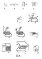
- FIG. 4 schematically shows a process sequence using the sample holder (holder 20, stand 40) according to the invention described in detail above, as is typical, for example, for carrying out an immunoassay:
- a test tube 60 contains, for example, the blood sample taken from a patient in which the substance of interest is to be detected (A).
- the serum used for the measurement which contains the analyte, is separated from the blood cells (B) and the serum is removed (C).
- the serum sample is usually stored temporarily as a primary sample (61) for distribution over several sample vessels for different tests.
- the relevant data such as the name of the patient, type of examination, etc., are recorded on a data carrier (Documentation D).
- sample vessels 30 are used, which are provided with a short identification in accordance with the documentation (E).
- the sample vessels 30 used here can already be provided with an antibody inner coating which is specific for the analyte to be detected.
- sample vessels are then inserted one after the other into the holders 20 placed on a stand 40 and pushed through to the bottom of the stand 40 (F), where their bottom dips into the holes 49 in the bottom 40.
- sample tubes can be placed in the holder at the manufacturer of the diagnostics. In this case, the tubes can be labeled very easily without having to remove them from the holder and readjust them after labeling.
- the serum taken from the primary sample and containing the analyte is poured into one of the sample vessels (G), then the next patient sample, etc., until, for example, all sample tubes contain the patient sample.
- the reagents in the case of the immunoassay the labeled antibodies or antigens, are then pipetted in (H). This can either be done while the samples are in the rack or you take one holder after the other to add reagents and then put it back in the rack.
- the stand 40 which is appropriately covered with holders, is then inserted into an incubator, in which the desired antigen-antibody reaction takes place, if appropriate at elevated temperature (I). For this it may be necessary to shake the stand with the holders to accelerate this run.
- the stands and the holders are then placed in a washing machine (K). If this is not available in the laboratory, the sample vessels can be filled with cleaning reagent and the entire sample rack (rack + glasses) decanted. This operation can also be required several times under certain circumstances.
- sample vessels thus prepared are then inserted holder by holder into a carrier element rotating in the actual measuring device 50 and then pass the measuring point, where the substances initiating chemiluminescence are added and the resulting light output is measured, the intensity of which is a measure of the amount of the substance to be detected in the analyte (L).
- the holders with the measured sample vessels are then removed from their associated carrier element and thrown away (M).
- the fixed holding of the sample vessels in the sample rack also enables safe joint handling, for example when shaking or decanting, without having to remove individual sample vessels or holders.
- sample tubes for example with a coating
- the sample tubes are already supplied by the diagnostics manufacturer in holders, since they can then remain in the holders from sample preparation to measurement and disposal.
- the concept of the sample holder according to the invention can also be advantageously used when using magnetic particles. It only has to be provided that the sample vessels must be in the area of influence of magnetic fields for effecting the separation and during the actual separation step, while on the other hand, e.g. B. during incubation phases, the magnetic field should not act.
- the stand can therefore also be designed in a known manner or with an open bottom surface so that it can be placed on a substructure which contains magnets which, after the modular rack has been placed on it, the magnetic field required for separation on the magnetic particles in the suspension exercise.
- the magnets generally permanent magnets, are arranged so that they either pull the magnetic particles to the bottom or, in the lower area, to the sides of the sample vessels.
- the combination of holder, stand and base is then tipped over as a unit for decanting.
- the combination of holder and stand can then be detached from the base and, for example, washing liquid added. Then the combination holder and stand can be placed on the substructure again, waiting for the magnetic particles to settle on the wall and then decanted again.
Landscapes
- Health & Medical Sciences (AREA)
- Clinical Laboratory Science (AREA)
- Chemical & Material Sciences (AREA)
- Chemical Kinetics & Catalysis (AREA)
- Automatic Analysis And Handling Materials Therefor (AREA)
- Devices For Use In Laboratory Experiments (AREA)
- Sampling And Sample Adjustment (AREA)
Claims (9)
- Support pour récipients d'échantillons (30), par exemple des tubes à essai, avec M x N ouvertures sur sa face supérieure pour la réception de M x N récipients d'échantillons (30), composé de M supports (20) identiques pour la réception linéaire de respectivement N récipients d'échantillons (30) et d'un châssis (40) pour la réception de M supports (20), chaque support étant constitué d'un élément (21) en matièrs plastique muni d'ouvertures (22) pour la réception des récipients d'échantillons (30) dans son axe longitudinal (Y-Y), et le châssis (40) présentant des éléments latéraux verticaux (40A, 40B) sur lesquels peuvent être déposés plusieurs supports (20), caractérisé en ce que les éléments (21) en matière plastique sont conformés pour la réception par adhérence des récipients d'échantillons (30), que l'élément (21) en matière plastique en forme d'étrier présente à chacune de ses extrémités frontales un rebord vertical (23A, 23B) et, dans le plan perpendiculaire à son axe longitudinal (Y-Y), une section transversale en U, entre les rebords verticaux (23A, 23B) et les surfaces latérales (24A, 24B) de l'élément (21) en matière plastique étant conformée une fente verticale (25A à D), que le rebord vertical (23A, B) présente dans sa région centrale inférieure un épaississement (26A, 26B) dirigé vers l'intérieur, que des deux côtés de l'épaississement (26A, 26B) est prévu à chaque fois un creux (27A, 27B), que les éléments latéraux verticaux (40A, 40B) du châssis (40) sont munis à leur extrémité supérieure de découpures rectangulaires (40D, E) dont l'écartement et la section transversale sont dimensionnés de telle façon que plusieurs supports (20) peuvent être posés parallèlement sur le châssis (40), leurs épaississements (26A, 26B) sur les rebords verticaux (23A, 23B) s'engageant dans les découpures (40D, E) lorsque les rebords verticaux (23A, 23B) coiffent extérieurement les éléments latéraux (40A, 40B) et que les éléments latéraux (40A, 40B) pénètrent dans les fentes (25A, B), et que de manière conjuguée avec les creux (27A, 27B) dans les rebords verticaux (23A, 23B) des supports (20), des saillies (41) sont conformées dans les éléments latéraux (40A, 40B), des deux côtés des découpures (40D, E), de manière à réaliser un verrouillage à crans entre les supports (20) et le châssis (40).
- Support pour récipients d'échantillons selon la revendication 1, caractérisé en ce que pour la réception par adhérence, les ouvertures (22) sont munies de languettes élastiques (22A) en matière plastique dirigées vers le bas qui, à l'état non chargé (sans récipient d'échantillons), se situent sur une aire latérale d'un tronc de cône dont l'axe est perpendiculaire à la face supérieure de l'élément (21) en matière plastique et qui s'écartent lors de l'introduction d'un récipient d'échantillons (30).
- Support pour récipients d'échantillons selon la revendication 1, caractérisé en ce que le support (20) comporte au moins sur l'un des côtés une baguette de préhension (28).
- Support pour récipient d'échantillons selon la revendication 1, caractérisé en ce que le châssis (40) comporte au moins sur l'un des côtés une baguette de préhension (48).
- Support pour récipients d'échantillons selon l'une des revendications précédentes, caractérisé en ce que les parties coopérantes du support (20) et du châssis (40) sont conformées de manière asymétrique par rapport au plan médian parallèle aux éléments latéraux, de sorte qu'un positionnement parallèle d'un support (20) par rapport au fond (40C) du châssis (40) n'est obtenu que dans une position d'introduction.
- Support pour récipients d'échantillons selon la revendication 5, caractérisé en ce que les épaississements (26A, 26B) et les découpures (40D, 40E) associées sont conformés de façon à être conjugués par paires (26A, 40D et respectivement 26B, 40E).
- Support pour récipients d'échantillons selon la revendication 1, caractérisé en ce que sur les surfaces latérales (24A, 24B) est appliqué un élément d'identification (29), par exemple sous la forme d'une bande code barres.
- Support pour récipients d'échantillons selon la revendication 1, caractérisé en ce que le fond (40C) du châssis (40) présente M x N alésages (49) qui se situent respectivement au-dessous d'une ouverture (22) des supports (20) montés.
- Support pour récipients d'échantillons selon la revendication 8, caractérisé en ce que la section transversale des alésages (49) diminue vers le bas.
Priority Applications (1)
| Application Number | Priority Date | Filing Date | Title |
|---|---|---|---|
| AT89117451T ATE93412T1 (de) | 1988-10-24 | 1989-09-21 | Probenhalterung fuer probengefaesse. |
Applications Claiming Priority (2)
| Application Number | Priority Date | Filing Date | Title |
|---|---|---|---|
| DE8813340U | 1988-10-24 | ||
| DE8813340U DE8813340U1 (de) | 1988-10-24 | 1988-10-24 | Probenrack für Probengefäße |
Publications (3)
| Publication Number | Publication Date |
|---|---|
| EP0365828A2 EP0365828A2 (fr) | 1990-05-02 |
| EP0365828A3 EP0365828A3 (fr) | 1991-01-30 |
| EP0365828B1 true EP0365828B1 (fr) | 1993-08-25 |
Family
ID=6829192
Family Applications (1)
| Application Number | Title | Priority Date | Filing Date |
|---|---|---|---|
| EP89117451A Expired - Lifetime EP0365828B1 (fr) | 1988-10-24 | 1989-09-21 | Support pour récipients d'échantillons |
Country Status (4)
| Country | Link |
|---|---|
| US (1) | US5098663A (fr) |
| EP (1) | EP0365828B1 (fr) |
| AT (1) | ATE93412T1 (fr) |
| DE (2) | DE8813340U1 (fr) |
Families Citing this family (72)
| Publication number | Priority date | Publication date | Assignee | Title |
|---|---|---|---|---|
| US5074505A (en) * | 1990-06-01 | 1991-12-24 | Akzo N.V. | Support attachment for holding bottles within a bottle block |
| USD340838S (en) | 1991-07-12 | 1993-11-02 | Lingo John L | Drinking glass |
| US5575978A (en) | 1992-03-27 | 1996-11-19 | Abbott Laboratories | Sample container segment assembly |
| DE4212471A1 (de) * | 1992-04-14 | 1993-10-28 | Ostma Maschinenbau Gmbh | In einen Verpackungskarton einzusetzender Träger für zu verpackende Gegenstände |
| US5324482A (en) * | 1992-08-27 | 1994-06-28 | David A. White | Pipette tip packaging system |
| US5571481A (en) * | 1995-02-17 | 1996-11-05 | Vicam, L.P. | Magnetic capture rack with slidable magnetic member |
| US5856194A (en) | 1996-09-19 | 1999-01-05 | Abbott Laboratories | Method for determination of item of interest in a sample |
| US5795784A (en) | 1996-09-19 | 1998-08-18 | Abbott Laboratories | Method of performing a process for determining an item of interest in a sample |
| DE904841T1 (de) * | 1997-09-29 | 2001-10-25 | F. Hoffmann-La Roche Ag, Basel | System zur Handhabung von Verbindungen, bestehend aus Gefässen und Trägern |
| US7060226B1 (en) | 1997-11-24 | 2006-06-13 | Medax International, Inc. | Pipette tip packaging and transfer system |
| US6193892B1 (en) | 1999-03-03 | 2001-02-27 | Promega Corporation | Magnetic separation assembly and method |
| USD446311S1 (en) | 1999-06-18 | 2001-08-07 | Wescott, Iii Harvey M. | Test tube receptacle |
| US6692700B2 (en) | 2001-02-14 | 2004-02-17 | Handylab, Inc. | Heat-reduction methods and systems related to microfluidic devices |
| US7829025B2 (en) | 2001-03-28 | 2010-11-09 | Venture Lending & Leasing Iv, Inc. | Systems and methods for thermal actuation of microfluidic devices |
| US6852287B2 (en) | 2001-09-12 | 2005-02-08 | Handylab, Inc. | Microfluidic devices having a reduced number of input and output connections |
| US8895311B1 (en) | 2001-03-28 | 2014-11-25 | Handylab, Inc. | Methods and systems for control of general purpose microfluidic devices |
| US7010391B2 (en) | 2001-03-28 | 2006-03-07 | Handylab, Inc. | Methods and systems for control of microfluidic devices |
| CN1113686C (zh) * | 2001-06-04 | 2003-07-09 | 易荣大 | 三维运动式旋混装置 |
| JP4133811B2 (ja) * | 2001-07-20 | 2008-08-13 | ジェン−プローブ・インコーポレーテッド | サンプルキャリアおよびそれと共に使用する滴下保護材 |
| US20030087447A1 (en) * | 2001-11-08 | 2003-05-08 | Blouin Matthew R | Sample well strip |
| USD481133S1 (en) | 2002-04-18 | 2003-10-21 | Instrumentation Laboratory Company | Sample well-strip for an automated sample analyzer |
| DE60307825T2 (de) | 2002-05-17 | 2007-03-01 | Gen-Probe Inc., San Diego | Probenträger mit feststelleinrichtung und zugehörige tropfschirmvorrichtung |
| ATE375823T1 (de) * | 2002-05-17 | 2007-11-15 | Gen Probe Inc | Probenträger mit lösbarer sperreinrichtung |
| WO2004105951A1 (fr) * | 2003-05-28 | 2004-12-09 | Hte Aktiengesellschaft The High Throughput Experimentation Company | Systeme porte-echantillons modulaire |
| EP1654066B1 (fr) | 2003-07-31 | 2014-11-12 | Handylab, Inc. | Traitement d'echantillons contenant des particules |
| US8852862B2 (en) | 2004-05-03 | 2014-10-07 | Handylab, Inc. | Method for processing polynucleotide-containing samples |
| EP1614476B1 (fr) * | 2004-07-06 | 2007-09-05 | Roche Diagnostics GmbH | Système de stockage avec un adaptateur |
| US7910067B2 (en) | 2005-04-19 | 2011-03-22 | Gen-Probe Incorporated | Sample tube holder |
| DE602005020298D1 (de) * | 2005-09-21 | 2010-05-12 | Roche Diagnostics Gmbh | Halter für Kuvetten, Kuvettenmatrix und Analysevorrichtung mit diesen Komponenten |
| US7998708B2 (en) | 2006-03-24 | 2011-08-16 | Handylab, Inc. | Microfluidic system for amplifying and detecting polynucleotides in parallel |
| US10900066B2 (en) | 2006-03-24 | 2021-01-26 | Handylab, Inc. | Microfluidic system for amplifying and detecting polynucleotides in parallel |
| US11806718B2 (en) | 2006-03-24 | 2023-11-07 | Handylab, Inc. | Fluorescence detector for microfluidic diagnostic system |
| US9040288B2 (en) | 2006-03-24 | 2015-05-26 | Handylab, Inc. | Integrated system for processing microfluidic samples, and method of using the same |
| EP1850136A1 (fr) * | 2006-04-28 | 2007-10-31 | F.Hoffmann-La Roche Ag | Dispositif mélangeur d'appareil d'analyse et analyseur comprenant un tel dispositif |
| WO2008061165A2 (fr) | 2006-11-14 | 2008-05-22 | Handylab, Inc. | Cartouche microfluidique et son procédé de fabrication |
| WO2008060604A2 (fr) | 2006-11-14 | 2008-05-22 | Handylab, Inc. | Système microfluidique utilisé pour amplifier et détecter des polynucléotides en parallèle |
| US7731899B2 (en) | 2007-02-08 | 2010-06-08 | Biokit, S.A. | Apparatus and methods for dispensing sample holders |
| USD563171S1 (en) | 2007-03-05 | 2008-03-04 | Mansfield Bryan D | Drinking vessel |
| USD572976S1 (en) | 2007-03-27 | 2008-07-15 | Mansfield Bryan D | Drinking vessel |
| US8182763B2 (en) | 2007-07-13 | 2012-05-22 | Handylab, Inc. | Rack for sample tubes and reagent holders |
| US9186677B2 (en) | 2007-07-13 | 2015-11-17 | Handylab, Inc. | Integrated apparatus for performing nucleic acid extraction and diagnostic testing on multiple biological samples |
| US8287820B2 (en) | 2007-07-13 | 2012-10-16 | Handylab, Inc. | Automated pipetting apparatus having a combined liquid pump and pipette head system |
| ES2648798T3 (es) | 2007-07-13 | 2018-01-08 | Handylab, Inc. | Materiales de captura de polinucleótidos y métodos de utilización de los mismos |
| US8105783B2 (en) | 2007-07-13 | 2012-01-31 | Handylab, Inc. | Microfluidic cartridge |
| US8133671B2 (en) | 2007-07-13 | 2012-03-13 | Handylab, Inc. | Integrated apparatus for performing nucleic acid extraction and diagnostic testing on multiple biological samples |
| US9618139B2 (en) | 2007-07-13 | 2017-04-11 | Handylab, Inc. | Integrated heater and magnetic separator |
| BRPI0818614B1 (pt) | 2007-10-23 | 2019-06-25 | Becton, Dickinson And Company | Sistema e método para armazenar uma amostra biológica |
| CA2816874C (fr) | 2007-10-23 | 2016-03-15 | Becton, Dickinson And Company | Systeme multicompartiment pour le confinement de tissus a des fins de diagnostics moleculaires et histologiques |
| USD787087S1 (en) | 2008-07-14 | 2017-05-16 | Handylab, Inc. | Housing |
| EP3663004B1 (fr) | 2009-05-15 | 2022-01-26 | Gen-Probe Incorporated | Procédé et appareil pour la réalisation d'une procédure de séparation magnétique |
| US9144801B2 (en) | 2010-08-31 | 2015-09-29 | Abbott Laboratories | Sample tube racks having retention bars |
| CN106190806B (zh) | 2011-04-15 | 2018-11-06 | 贝克顿·迪金森公司 | 扫描实时微流体热循环仪和用于同步的热循环和扫描光学检测的方法 |
| DK2761305T3 (da) | 2011-09-30 | 2017-11-20 | Becton Dickinson Co | Forenet reagensstrimmel |
| USD692162S1 (en) | 2011-09-30 | 2013-10-22 | Becton, Dickinson And Company | Single piece reagent holder |
| WO2013067202A1 (fr) | 2011-11-04 | 2013-05-10 | Handylab, Inc. | Dispositif de préparation d'échantillons de polynucléotides |
| DK2810080T3 (da) | 2012-02-03 | 2024-06-17 | Becton Dickinson Co | Eksterne filer til fordeling af molekylære diagnostiske tests og bestemmelse af kompatabilitet imellem tests |
| EP2732878B1 (fr) * | 2012-11-20 | 2018-09-12 | QIAGEN GmbH | Système de grille magnétique et procédé d'utilisation d'un système de grille magnétique |
| USD814653S1 (en) | 2014-08-07 | 2018-04-03 | Becton, Dickinson And Company | Sample tube holder and components thereof |
| US10634584B2 (en) * | 2015-12-17 | 2020-04-28 | Roku, Inc. | Device for microscopic sample collection |
| US10392183B2 (en) * | 2016-06-06 | 2019-08-27 | Christopher Joseph-Paul Link | Funnel storage systems |
| TWI626992B (zh) * | 2017-08-08 | 2018-06-21 | 元昌生技醫療私人股份有限公司 | 試管準直檢驗裝置 |
| IT201700116211A1 (it) | 2017-10-16 | 2019-04-16 | Inpeco Holding Ltd | Sistema di tracciabilità del trasporto di contenitori di campioni biologici |
| US11260400B2 (en) * | 2017-10-30 | 2022-03-01 | Nanjing GenScript Biotech Co., Ltd. | Inclined magnetic holder |
| CN107971059B (zh) * | 2018-01-12 | 2019-11-12 | 田艳 | 一种便携式血液检验试管架 |
| US10932647B1 (en) | 2018-04-25 | 2021-03-02 | 4 R Oceans, LLC | Drinking straw cleaning caddy |
| US10694922B1 (en) * | 2018-04-25 | 2020-06-30 | 4 R Oceans, LLC | Drinking straw cleaning caddy |
| US20210325416A1 (en) * | 2020-04-11 | 2021-10-21 | Mitchell Olin Setzer, SR. | Vial grabber inspection apparatus |
| USD981005S1 (en) * | 2020-04-14 | 2023-03-14 | Aesculap Ag | Sterile container labelling plate |
| CN111774123B (zh) * | 2020-07-31 | 2021-08-31 | 中国人民解放军陆军军医大学第一附属医院 | 标本放置架 |
| US20240215878A1 (en) * | 2021-04-27 | 2024-07-04 | Micro Lab Solutions, Llc | Blood collection assembly and method of using the same |
| CN113198560B (zh) * | 2021-05-06 | 2022-06-17 | 佳木斯大学 | 一种血标本试管架及识别报警方法 |
| USD1052257S1 (en) * | 2024-06-29 | 2024-11-26 | Nanjing Langs Electronics Technology Co., Ltd | Capsule holder |
Family Cites Families (12)
| Publication number | Priority date | Publication date | Assignee | Title |
|---|---|---|---|---|
| US3713771A (en) * | 1971-05-13 | 1973-01-30 | B Taylor | Method for organized assay and bendable test tube rack therefor |
| GB1402283A (en) * | 1971-10-14 | 1975-08-06 | Coulter Electronics | Automatic chemical analysis apparatus |
| US3785773A (en) * | 1972-03-02 | 1974-01-15 | Beckman Instruments Inc | Chemical analysis tube module |
| GB1486210A (en) * | 1973-11-14 | 1977-09-21 | Suovaniemi Osmo Antero | Cuvette assembly for use in automatic reading and recording of reaction results |
| FR2277013A1 (fr) * | 1974-07-05 | 1976-01-30 | Intertechnique Sa | Perfectionnements aux convoyeurs d'echantillons pour appareil de mesure |
| US4055396A (en) * | 1975-07-11 | 1977-10-25 | G. D. Searle & Co. | Tray and carrier assembly |
| DE2730214A1 (de) * | 1977-07-04 | 1979-01-11 | Franz Liebl | Mehrfachprobenstaender fuer labor- untersuchungen |
| SE8004687L (sv) * | 1980-06-25 | 1981-12-26 | Clinicon Ab | Automatisk analysapparat |
| US4495150A (en) * | 1983-07-25 | 1985-01-22 | Beckman Instruments, Inc. | Multiple object capturing and processing device |
| DE3405292A1 (de) * | 1984-02-15 | 1985-09-05 | Eppendorf Gerätebau Netheler + Hinz GmbH, 2000 Hamburg | Verfahren zum durchfuehren von probenanalysen sowie rack zur durchfuehrung des verfahrens |
| IT209233Z2 (it) * | 1985-10-14 | 1988-09-20 | Alfi Srl | Struttura di stativo per il supporto ed il contenimento di provette e simili. |
| US4895650A (en) * | 1988-02-25 | 1990-01-23 | Gen-Probe Incorporated | Magnetic separation rack for diagnostic assays |
-
1988
- 1988-10-24 DE DE8813340U patent/DE8813340U1/de not_active Expired
-
1989
- 1989-09-21 EP EP89117451A patent/EP0365828B1/fr not_active Expired - Lifetime
- 1989-09-21 DE DE89117451T patent/DE58905378D1/de not_active Expired - Fee Related
- 1989-09-21 AT AT89117451T patent/ATE93412T1/de not_active IP Right Cessation
- 1989-10-24 US US07/426,300 patent/US5098663A/en not_active Expired - Fee Related
Also Published As
| Publication number | Publication date |
|---|---|
| US5098663A (en) | 1992-03-24 |
| DE8813340U1 (de) | 1988-12-08 |
| EP0365828A2 (fr) | 1990-05-02 |
| ATE93412T1 (de) | 1993-09-15 |
| EP0365828A3 (fr) | 1991-01-30 |
| DE58905378D1 (de) | 1993-09-30 |
Similar Documents
| Publication | Publication Date | Title |
|---|---|---|
| EP0365828A2 (fr) | Support pour récipients d'échantillons | |
| EP0365827B1 (fr) | Dispositif de réception pour plusieurs récipients d'échantillons en vue de mesures radiométriques | |
| DE69308493T2 (de) | Träger für proberöhrchen | |
| DE60307825T2 (de) | Probenträger mit feststelleinrichtung und zugehörige tropfschirmvorrichtung | |
| EP2927163B1 (fr) | Dispositif de transport vertical, système de distribution d'échantillons et système d'automatisation de laboratoire | |
| DE2432086C2 (de) | Apparatur zur Blutgruppenbestimmung mit einer Reagenzglaseinheit | |
| DE69904726T2 (de) | Automatisches immunoassay-gerät mit flexiblem hebearm | |
| DE60316938T2 (de) | Probenträger mit lösbarer sperreinrichtung | |
| DE2349901C3 (de) | Vorrichtung zum reihenweisen Transport von geradlinig hintereinander angeordneten Probengefäßen | |
| DE4313807C2 (de) | Reagenz-Container-System für die immunologische Analyse einer Probe in einem automatischen Analysiergerät | |
| DE69833846T2 (de) | Vorrichtung zum Befördern von Komponenten innerhalb eines automatischen Analysesystems | |
| EP0849584A2 (fr) | Dispositif (cuvette) pour recevoir et stocker des liquides et pour effecteur des mesures optiques | |
| DE2103841A1 (de) | Blutuntersuchungsvorrichtung | |
| DE3750446T2 (de) | Reagenzkassette. | |
| EP1662261A1 (fr) | Dispositif d'analyse d'échantillons | |
| EP3666381B1 (fr) | Appareil automatique de laboratoire destiné au traitement automatique des échantillons de laboratoire | |
| DE69413643T2 (de) | Probentraeger | |
| EP0306438B1 (fr) | Dispositif à recevoir une pluralité d'éléments de support | |
| JPS63502929A (ja) | モジュール式貯蔵機構 | |
| DE3313127A1 (de) | Vorrichtung zum faerben von biologischen proben | |
| DE19512430A1 (de) | Mikrotiterplatte | |
| DE3882783T2 (de) | Verschliess-Einschubbehälter und zugehöriger Wegwerf-Probenträger. | |
| EP4091715A1 (fr) | Syst?me de bandelette réactive pourvu de récipients | |
| DE4329791A1 (de) | Verfahren und Einrichtung zur automatischen Verteilung von Mikrofilterscheiben | |
| EP1310303B1 (fr) | Reservoir pour plusieurs reactifs differents necessaires a un systeme de dosage |
Legal Events
| Date | Code | Title | Description |
|---|---|---|---|
| PUAI | Public reference made under article 153(3) epc to a published international application that has entered the european phase |
Free format text: ORIGINAL CODE: 0009012 |
|
| AK | Designated contracting states |
Kind code of ref document: A2 Designated state(s): AT CH DE ES FR GB IT LI NL SE |
|
| PUAL | Search report despatched |
Free format text: ORIGINAL CODE: 0009013 |
|
| AK | Designated contracting states |
Kind code of ref document: A3 Designated state(s): AT CH DE ES FR GB IT LI NL SE |
|
| 17P | Request for examination filed |
Effective date: 19910702 |
|
| 17Q | First examination report despatched |
Effective date: 19920602 |
|
| RAP1 | Party data changed (applicant data changed or rights of an application transferred) |
Owner name: LABORATORIUM PROF. DR. RUDOLF BERTHOLD GMBH & CO. |
|
| GRAA | (expected) grant |
Free format text: ORIGINAL CODE: 0009210 |
|
| AK | Designated contracting states |
Kind code of ref document: B1 Designated state(s): AT CH DE ES FR GB IT LI NL SE |
|
| PG25 | Lapsed in a contracting state [announced via postgrant information from national office to epo] |
Ref country code: IT Free format text: LAPSE BECAUSE OF FAILURE TO SUBMIT A TRANSLATION OF THE DESCRIPTION OR TO PAY THE FEE WITHIN THE PRE;WARNING: LAPSES OF ITALIAN PATENTS WITH EFFECTIVE DATE BEFORE 2007 MAY HAVE OCCURRED AT ANY TIME BEFORE 2007. THE CORRECT EFFECTIVE DATE MAY BE DIFFERENT FROM THE ONE RECORDED.SCRIBED TIME-LIMIT Effective date: 19930825 Ref country code: NL Effective date: 19930825 Ref country code: SE Effective date: 19930825 Ref country code: ES Free format text: THE PATENT HAS BEEN ANNULLED BY A DECISION OF A NATIONAL AUTHORITY Effective date: 19930825 |
|
| REF | Corresponds to: |
Ref document number: 93412 Country of ref document: AT Date of ref document: 19930915 Kind code of ref document: T |
|
| PG25 | Lapsed in a contracting state [announced via postgrant information from national office to epo] |
Ref country code: AT Effective date: 19930921 |
|
| PG25 | Lapsed in a contracting state [announced via postgrant information from national office to epo] |
Ref country code: CH Effective date: 19930930 Ref country code: LI Effective date: 19930930 |
|
| REF | Corresponds to: |
Ref document number: 58905378 Country of ref document: DE Date of ref document: 19930930 |
|
| ET | Fr: translation filed | ||
| GBT | Gb: translation of ep patent filed (gb section 77(6)(a)/1977) |
Effective date: 19931123 |
|
| NLV1 | Nl: lapsed or annulled due to failure to fulfill the requirements of art. 29p and 29m of the patents act | ||
| REG | Reference to a national code |
Ref country code: CH Ref legal event code: PL |
|
| PLBE | No opposition filed within time limit |
Free format text: ORIGINAL CODE: 0009261 |
|
| STAA | Information on the status of an ep patent application or granted ep patent |
Free format text: STATUS: NO OPPOSITION FILED WITHIN TIME LIMIT |
|
| PGFP | Annual fee paid to national office [announced via postgrant information from national office to epo] |
Ref country code: DE Payment date: 19940714 Year of fee payment: 6 |
|
| 26N | No opposition filed | ||
| PGFP | Annual fee paid to national office [announced via postgrant information from national office to epo] |
Ref country code: GB Payment date: 19940905 Year of fee payment: 6 |
|
| PGFP | Annual fee paid to national office [announced via postgrant information from national office to epo] |
Ref country code: FR Payment date: 19940919 Year of fee payment: 6 |
|
| PG25 | Lapsed in a contracting state [announced via postgrant information from national office to epo] |
Ref country code: GB Effective date: 19950921 |
|
| GBPC | Gb: european patent ceased through non-payment of renewal fee |
Effective date: 19950921 |
|
| PG25 | Lapsed in a contracting state [announced via postgrant information from national office to epo] |
Ref country code: FR Effective date: 19960531 |
|
| PG25 | Lapsed in a contracting state [announced via postgrant information from national office to epo] |
Ref country code: DE Effective date: 19960601 |
|
| REG | Reference to a national code |
Ref country code: FR Ref legal event code: ST |