EP0365860A1 - Connecteur d'air pour un Sphygmomanomètre - Google Patents
Connecteur d'air pour un Sphygmomanomètre Download PDFInfo
- Publication number
- EP0365860A1 EP0365860A1 EP89117906A EP89117906A EP0365860A1 EP 0365860 A1 EP0365860 A1 EP 0365860A1 EP 89117906 A EP89117906 A EP 89117906A EP 89117906 A EP89117906 A EP 89117906A EP 0365860 A1 EP0365860 A1 EP 0365860A1
- Authority
- EP
- European Patent Office
- Prior art keywords
- air
- plug
- line
- socket
- acceptor
- Prior art date
- Legal status (The legal status is an assumption and is not a legal conclusion. Google has not performed a legal analysis and makes no representation as to the accuracy of the status listed.)
- Granted
Links
- 230000006854 communication Effects 0.000 claims abstract description 11
- 238000004891 communication Methods 0.000 claims abstract description 11
- 238000009434 installation Methods 0.000 claims abstract description 5
- 230000000295 complement effect Effects 0.000 claims description 4
- 238000003556 assay Methods 0.000 abstract description 27
- 230000036772 blood pressure Effects 0.000 abstract description 7
- 238000003780 insertion Methods 0.000 description 7
- 230000037431 insertion Effects 0.000 description 7
- 230000006835 compression Effects 0.000 description 3
- 238000007906 compression Methods 0.000 description 3
- 238000000034 method Methods 0.000 description 3
- 230000008034 disappearance Effects 0.000 description 2
- 230000002093 peripheral effect Effects 0.000 description 2
- 230000004872 arterial blood pressure Effects 0.000 description 1
- 210000001367 artery Anatomy 0.000 description 1
- 239000008280 blood Substances 0.000 description 1
- 210000004369 blood Anatomy 0.000 description 1
- 230000017531 blood circulation Effects 0.000 description 1
- 230000035487 diastolic blood pressure Effects 0.000 description 1
- 230000009977 dual effect Effects 0.000 description 1
- 230000013011 mating Effects 0.000 description 1
- 230000035488 systolic blood pressure Effects 0.000 description 1
Images


Classifications
-
- A—HUMAN NECESSITIES
- A61—MEDICAL OR VETERINARY SCIENCE; HYGIENE
- A61B—DIAGNOSIS; SURGERY; IDENTIFICATION
- A61B5/00—Measuring for diagnostic purposes; Identification of persons
- A61B5/02—Detecting, measuring or recording for evaluating the cardiovascular system, e.g. pulse, heart rate, blood pressure or blood flow
- A61B5/021—Measuring pressure in heart or blood vessels
- A61B5/02141—Details of apparatus construction, e.g. pump units or housings therefor, cuff pressurising systems, arrangements of fluid conduits or circuits
-
- A—HUMAN NECESSITIES
- A61—MEDICAL OR VETERINARY SCIENCE; HYGIENE
- A61B—DIAGNOSIS; SURGERY; IDENTIFICATION
- A61B5/00—Measuring for diagnostic purposes; Identification of persons
- A61B5/02—Detecting, measuring or recording for evaluating the cardiovascular system, e.g. pulse, heart rate, blood pressure or blood flow
- A61B5/021—Measuring pressure in heart or blood vessels
- A61B5/022—Measuring pressure in heart or blood vessels by applying pressure to close blood vessels, e.g. against the skin; Ophthalmodynamometers
- A61B5/02233—Occluders specially adapted therefor
-
- Y—GENERAL TAGGING OF NEW TECHNOLOGICAL DEVELOPMENTS; GENERAL TAGGING OF CROSS-SECTIONAL TECHNOLOGIES SPANNING OVER SEVERAL SECTIONS OF THE IPC; TECHNICAL SUBJECTS COVERED BY FORMER USPC CROSS-REFERENCE ART COLLECTIONS [XRACs] AND DIGESTS
- Y10—TECHNICAL SUBJECTS COVERED BY FORMER USPC
- Y10T—TECHNICAL SUBJECTS COVERED BY FORMER US CLASSIFICATION
- Y10T137/00—Fluid handling
- Y10T137/8593—Systems
- Y10T137/877—With flow control means for branched passages
-
- Y—GENERAL TAGGING OF NEW TECHNOLOGICAL DEVELOPMENTS; GENERAL TAGGING OF CROSS-SECTIONAL TECHNOLOGIES SPANNING OVER SEVERAL SECTIONS OF THE IPC; TECHNICAL SUBJECTS COVERED BY FORMER USPC CROSS-REFERENCE ART COLLECTIONS [XRACs] AND DIGESTS
- Y10—TECHNICAL SUBJECTS COVERED BY FORMER USPC
- Y10T—TECHNICAL SUBJECTS COVERED BY FORMER US CLASSIFICATION
- Y10T137/00—Fluid handling
- Y10T137/8593—Systems
- Y10T137/877—With flow control means for branched passages
- Y10T137/87788—With valve or movable deflector at junction
- Y10T137/87804—Valve or deflector is tubular passageway
Definitions
- the present invention relates to a sphygmomanometer air connector for pneumatic connection between a sphygmomanometer body and a pneumatic cuff.
- the sphygmomanometer has a built-in air system including a compression pump, a pressure sensor for detecting the pressure of a pneumatic cuff, a slow-speed exhaust valve and so on.
- the air tube of the cuff is connected to the above pneumatic system through an air connector and the cuff is compressed by the compression pump (not shown).
- the pneumatic cuff is set on the upper arm of the subject and the air compressed by the compression pump is delivered to the pneumatic cuff to arrest the blood flow in the bracheal artery.
- the appearance and disappearance of the Korotkoff sounds are detected and the cuff pressure at the appearance of the K sounds is taken as the systolic blood pressure while the cuff pressure at the disappearance of the sounds is regarded as the diastolic pressure.
- the sphygmomanometer is subject to the Metric Law which provides that air leaks shall not be more than 4 mmHg in 3 minutes and, as such, is assayed item-by-item by the metric assay authority.
- compressed air must be supplied exclusively to the built-into pressure gauge (pressure measuring means) of the sphygmomanometer.
- pressure measuring means pressure measuring means
- This sphygmomanometer air connector comprises, as used in association with a sphygmomanometer body 61, an air socket 65 having a pressure measuring air line 63 and an exhaust air line 64 each communicating with an air plug acceptor 62, a short-length air supply plug 67 [See Fig.
- the short-length air plug 67 illustrated in Fig. 5(B) is inserted into the air socket 65.
- the air plug 67 is provided with a joint 67a for connection of the air tube of the pneumatic cuff at one end (base) thereof, while the tapered portion 67b at the other end (tip) is abutted against a tapered wall 65a at the plug acceptor 62 of the air socket 65.
- the forward end of the air plug 67 is detained short of the position of the exhaust air line 64 and that of the pressure measuring air line 63, with the result that the pressure measuring air line 63 and exhaust air line 64 are brought into communication with the air supply line 66 of the air plug 67.
- the air system of the sphygmomanometer communicates with the pneumatic cuff. Hence, sphygmomanometry can be executed.
- the long-length auxiliary plug 69 is inserted into the air socket 65 [See Fig. 5 (A)]. That is to say, the air plug 67 fitted into the air socket 65 is disconnected and instead, the auxiliary plug 69 is inserted.
- the auxiliary plug 69 is formed at one end (base) thereof with a joint 69a′ for connection of the air tube of the assay pneumatic system and at the other end a tapered position 69b complementary with the taper 65a of the air socket 65, with a forward reduced-diameter part 69c of said tapered position 69b being provided with an opening 69d which communicates with the air supply line 68 and a closure rubber piece 69e being attached to the forward end of said reduced-diameter part 69c. Therefore, upon insertion of the auxiliary plug 69, the closure rubber piece 69e obstructs the exhaust air line 63.
- this sphygmomanometer air connector requires an auxiliary plug for pressure assay in addition to the air plug for blood pressure determination. Therefore, the product sphygmomanometer must be supplied with the auxiliary plug, which is unnecessary for blood pressure determination, as an attachment, thus contributing to an increased product price but an increased risk of missing the auxiliary plug which is not frequently used.
- It is an object of the present invention is to solve the above-mentioned problems and provide a convenient sphygmomanometer air connector having a single air plug member which can serve the dual purpose of sphygmomanometry and pressure assay.
- Other objects and advantages of the present invention wil become apparent as the following description of the invention proceeds.
- the sphygmomanometer air connector of the present invention comprises, as installed in association with a sphygmomanometer body, an air socket having an air plug acceptor and a pressure measuring air line and an exhaust air line each communicating with said air plug acceptor, an air supply plug dismountably connected to the air plug acceptor of said air socket and having an air tube joint at one end thereof and an insert cylinder member at the other end, and a control means which is dismountably connected to the insert cylinder of said air supply plug and, upon installation, brings the air supply line of said air supply plug into communication with said pressure measuring air line and exhaust air line and, upon removal, brings the air supply line of said air supply plug into communication with said pressure measuring air line.
- a cylindrical control means having a thread on its inner circumferential surface fits over the insert cylinder having a mating thread and locked in position as the threads are meshed with each other.
- the air tube of a pneumatic cuff is connected to the joint at the other end of the air plug.
- the forward end of the insert cylinder of the air plug enters into the air plug acceptor of the air socket and is locked in position by the O-ring of the air socket.
- the end face of the control means (cylinder) is abutted against the open end of the air socket (the end face exposed from the sphygmomanometer body).
- the depth of insertion of the insert cylinder is controlled “shallow" by the length of the control means (cylindrical member) so that the forward end of the insert cylinder is positioned behind the opening of the pressure measuring air line. Furthermore, since the outer diameter of the insert cylinder is smaller than the diameter of the plug acceptor, there is a clearance between the outer peripheral surface of the insert cyinder and the opening of the exhaust air line. Therefore, in normal condition, the pneumatic system of the sphygmomanometer (blood measuring air line and exhaust air line) communicates with the air supply line of the air plug. Stated differently, the pneumatic system of the sphygmomanometer body is communicating with the pneumatic cuff, thus enabling execution of blood pressure determination.
- the control means is threaded off from the air plug.
- the insert cylinder is inserted into the plug acceptor of the air socket. Since the insert cylinder by now has no control means, it can be inserted deeper into the plug acceptor so that the forward end of the insert cylinder sealingly engages the opening of the pressure measuring air line of the air socket. Therefore, the air supply line of the air plug communicates selectively with the pressure measuring air line of the sphygmomanometer alone, with its exhaust air line not communicating with the air supply line of the air plug. Stated differently, only the exhaust air line is obstructed.
- the single air plug can be used for both sphygmomanometry and pressure assay.
- Fig. 1 is a sectional elevation view showing a specific embodiment of the sphygmomanometer air connector according to the present invention.
- This sphygmomanometer air connector comprises an air socket 2, which is attached to a sphygmomanometer body 1, an air plug 3 which is removably inserted into said air socket 2, and a control means 4 which is dismountably connected to said air plug 3 and adapted to control the depth of insertion of the air plug 2 with respect to the air socket 1.
- the air socket 2 is a generally cylindrical hollow element 22 having a flange 21 at one open end and defining a bore which serves as a plug socket 23, with the inner circumference of said cylinder 22 being progressively reduced toward the other end to define a tapered bore 24 in contiguity with the first-mentioned bore. Formed further in continuity with said tapered bore 24 is a reduced-diameter bore 26 which serves as a pressure measuring air line 25. In addition, an exhaust air line 27 is formed through the wall of the cylinder 22 at an appropriate position as illustrated.
- This air socket 2 is mounted on the sphygmomanometer body 1 with said flange 21 extending out.
- the above-mentioned air plug 3 comprises a flat cylinder 3a formed with a tapered air tube joint 31 at one end (base) and an insert cylinder 32 which is smaller in diameter than said plug acceptor 23 at the other end (tip).
- an air supply line 33 extending from said one end to said other end.
- a thread 34 of expanded diameter is formed at the base of the insert cylinder 32 (on the forward side of the cylinder 3a).
- the forward end of the insert cylinder 32 is formed with a tapered portion 35 which is complementary with said tapered surface 24 of air socket 2 and the tip of this tapered portion 35 is adapted to sealingly engage with the opening of the pressure measuring air line 25.
- the above-mentioned control means 4 comprises a cylindrical element 41 having an outer diameter equal to that of the cylinder 3a of said air plug 3 and a thread 42 adapted to mesh with the thread 34 of said air plug 3.
- This thread 42 is formed from one end (base) of the cylinder 41 to the middle of its length and the portion of the cylinder 41 which is extending from the end of said thread 42 to the other end (tip) is slightly reduced in inner diameter to define a stop portion for delimiting the forward plane of said thread 34.
- this control means 4 is removably connected to the insert cylinder 32 of air plug 3 and locked with respect to the air plug 3 as its thread 42 engages the thread 34. In normal condition, the control means 4 is connected to the air plug 3 and the insert cylinder 32 is inserted into the plug acceptor 24 of air socket 2 and locked in position by the O-ring at the opening end of the air socket 2.
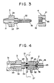
- Fig. 4 is a sectional elevation view showing another embodiment of the air connector.
- this second embodiment is so constructed that the opening 25a of the pressurizing measuring air line 25 of air socket 2 projects inwardly into the plug socket 24 and this projecting opening 25a sealingly engages the tip opening 36 of the insert cylinder 32.
- the depth of insertion of the insert cylinder 32 is controlled “shallower" by the length of control means 4 (cylindrical element) (the length of the stop portion 43 of the cylinder 41), so that the forward end of the insert cylinder 32 is set in a position reawardly displaced from the opening of the pressure measuring air line 25. Furthermore, since the outer diameter of the insert cylinder 32 is smaller than the diameter of the plug acceptor of the air socket 2, there is a clearance between the peripheral surface of the insert cylinder 32 and the opening of the exhaust air line 27. Therefore, in the normal condition, the pneumatic system of sphygmomanometer 1 (pressure measuring air line 25 and exhaust air line 27) is communicating with the air supply line 33 of the air plug 3. That is to say, the air system of the sphygmomanometer is communicating with the pneumatic cuff so that sphygmomanometry can be executed.
- the pneumatic system of sphygmomanometer 1 pressure measuring air line 25 and exhaust air line 27
- the control means 5 is threaded off from the air plug 3.
- the insert cylinder 32 now of the air plug 3 is inserted into the plug acceptor 23 of the air socket 2. Since the insert cylinder 32 now does not carry the control means 4, it enters deep into the plug acceptor 23 until its forward end sealingly engages the open end of the pressure measuring air line 25 of the air socket 2.
- the air supply line 33 of air plug 3 communicates only to the pressure measuring air line 25 of sphygmomanometer 1, with its exhaust air line 27 not communicating with the air supply line 33.
- the pressure array of the sphygmomanometer can be executed.
- both sphygmomanometry and pressure assay can be performed using the same single air plug 3, by dismounting the control means 4 from the air plug 3 only for pressure assay.
- the control means limits said depth of insertion to bring the pressure measuring air line and exhaust air line of the air socket into communication with the air supply line of the air plug for execution of sphygmomanometry.
- the plug can be inserted deeper so that the forward end of the air supply line of the air plug is selectively brought into communication with the pressure measuring air line alone, with the exhaust air line being obstructed, for execution of pressure assay.
- the present invention therefore, provides the advantage that the mere mounting and dismounting of a control means with respect to an air plug enables selective execution of blood pressure determination and sphygmomanometer pressure assay.
Landscapes
- Health & Medical Sciences (AREA)
- Life Sciences & Earth Sciences (AREA)
- Cardiology (AREA)
- Vascular Medicine (AREA)
- Engineering & Computer Science (AREA)
- Medical Informatics (AREA)
- Physics & Mathematics (AREA)
- Veterinary Medicine (AREA)
- Biophysics (AREA)
- Pathology (AREA)
- Public Health (AREA)
- Biomedical Technology (AREA)
- Heart & Thoracic Surgery (AREA)
- Physiology (AREA)
- Molecular Biology (AREA)
- Surgery (AREA)
- Animal Behavior & Ethology (AREA)
- General Health & Medical Sciences (AREA)
- Dentistry (AREA)
- Ophthalmology & Optometry (AREA)
- Measuring Pulse, Heart Rate, Blood Pressure Or Blood Flow (AREA)
Applications Claiming Priority (2)
| Application Number | Priority Date | Filing Date | Title |
|---|---|---|---|
| JP127669/88U | 1988-09-28 | ||
| JP1988127669U JPH061124Y2 (ja) | 1988-09-28 | 1988-09-28 | 血圧計のエアコネクタ |
Publications (2)
| Publication Number | Publication Date |
|---|---|
| EP0365860A1 true EP0365860A1 (fr) | 1990-05-02 |
| EP0365860B1 EP0365860B1 (fr) | 1994-06-01 |
Family
ID=14965790
Family Applications (1)
| Application Number | Title | Priority Date | Filing Date |
|---|---|---|---|
| EP89117906A Expired - Lifetime EP0365860B1 (fr) | 1988-09-28 | 1989-09-27 | Connecteur d'air pour un Sphygmomanomètre |
Country Status (5)
| Country | Link |
|---|---|
| US (1) | US5014716A (fr) |
| EP (1) | EP0365860B1 (fr) |
| JP (1) | JPH061124Y2 (fr) |
| AT (1) | ATE106216T1 (fr) |
| DE (1) | DE68915685T2 (fr) |
Cited By (1)
| Publication number | Priority date | Publication date | Assignee | Title |
|---|---|---|---|---|
| FR3086160A1 (fr) * | 2018-09-26 | 2020-03-27 | Spengler Sas | Systeme de connectique pour sphygmomanometre |
Families Citing this family (5)
| Publication number | Priority date | Publication date | Assignee | Title |
|---|---|---|---|---|
| JPH084578B2 (ja) * | 1991-06-24 | 1996-01-24 | 株式会社エー・アンド・デイ | 電子血圧計におけるエア給排路構造 |
| DE10214759A1 (de) * | 2002-04-03 | 2003-10-16 | Lactec Ges Fuer Moderne Lackte | Ventil |
| US7429027B2 (en) * | 2006-02-08 | 2008-09-30 | Mocon, Inc. | Self-flushing needle valve |
| CN108888252A (zh) * | 2018-05-03 | 2018-11-27 | 谢娟 | 一种医用血压测量装置 |
| USD984639S1 (en) * | 2022-11-10 | 2023-04-25 | Zejia Fang | Cuff connector |
Citations (5)
| Publication number | Priority date | Publication date | Assignee | Title |
|---|---|---|---|---|
| US3030945A (en) * | 1961-01-06 | 1962-04-24 | Clark Co Inc David | Shutoff control valve for sphygmomanometer |
| US3254671A (en) * | 1964-08-24 | 1966-06-07 | Emanuel R Berliner | Push control valve for instant deflation of blood pressure instruments |
| US4098291A (en) * | 1976-10-12 | 1978-07-04 | Manoscope, Inc. | Pressure relief valve |
| DE3011901A1 (de) * | 1979-04-23 | 1980-10-30 | Medos Kenkyusho Kk | Vorrichtung zur verhinderung der ansammlung von feuchtigkeit am betrachtungsobjektivfenster eines endoskops |
| EP0079617A2 (fr) * | 1981-11-17 | 1983-05-25 | Firma Richard Kallmeyer | Soupape d'évacuation pour sphygmomanomètre |
Family Cites Families (1)
| Publication number | Priority date | Publication date | Assignee | Title |
|---|---|---|---|---|
| DE14386C (de) * | W. STAINTON in London | Neuerungen an Heifswasserapparaten |
-
1988
- 1988-09-28 JP JP1988127669U patent/JPH061124Y2/ja not_active Expired - Lifetime
-
1989
- 1989-09-22 US US07/410,887 patent/US5014716A/en not_active Expired - Lifetime
- 1989-09-27 EP EP89117906A patent/EP0365860B1/fr not_active Expired - Lifetime
- 1989-09-27 AT AT89117906T patent/ATE106216T1/de not_active IP Right Cessation
- 1989-09-27 DE DE68915685T patent/DE68915685T2/de not_active Expired - Fee Related
Patent Citations (5)
| Publication number | Priority date | Publication date | Assignee | Title |
|---|---|---|---|---|
| US3030945A (en) * | 1961-01-06 | 1962-04-24 | Clark Co Inc David | Shutoff control valve for sphygmomanometer |
| US3254671A (en) * | 1964-08-24 | 1966-06-07 | Emanuel R Berliner | Push control valve for instant deflation of blood pressure instruments |
| US4098291A (en) * | 1976-10-12 | 1978-07-04 | Manoscope, Inc. | Pressure relief valve |
| DE3011901A1 (de) * | 1979-04-23 | 1980-10-30 | Medos Kenkyusho Kk | Vorrichtung zur verhinderung der ansammlung von feuchtigkeit am betrachtungsobjektivfenster eines endoskops |
| EP0079617A2 (fr) * | 1981-11-17 | 1983-05-25 | Firma Richard Kallmeyer | Soupape d'évacuation pour sphygmomanomètre |
Cited By (3)
| Publication number | Priority date | Publication date | Assignee | Title |
|---|---|---|---|---|
| FR3086160A1 (fr) * | 2018-09-26 | 2020-03-27 | Spengler Sas | Systeme de connectique pour sphygmomanometre |
| WO2020065239A1 (fr) * | 2018-09-26 | 2020-04-02 | Spengler Sas | Systeme de connectique pour sphygmomanometre |
| CN112752542A (zh) * | 2018-09-26 | 2021-05-04 | 斯宾格勒公司 | 血压计连接系统 |
Also Published As
| Publication number | Publication date |
|---|---|
| JPH061124Y2 (ja) | 1994-01-12 |
| DE68915685D1 (de) | 1994-07-07 |
| DE68915685T2 (de) | 1995-02-02 |
| US5014716A (en) | 1991-05-14 |
| EP0365860B1 (fr) | 1994-06-01 |
| JPH0249504U (fr) | 1990-04-06 |
| ATE106216T1 (de) | 1994-06-15 |
Similar Documents
| Publication | Publication Date | Title |
|---|---|---|
| US6159157A (en) | Blood pressure measurement device with a sensor locator | |
| US20040181254A1 (en) | Sphygmomanometer cuff having double bladder | |
| EP0460199A1 (fr) | Brassard universel auto-ajustable de mesure de la pression arterielle | |
| US3906939A (en) | Blood pressure measuring means | |
| CA2263396A1 (fr) | Systeme de monitorage de la temperature et de la pression d'un pneu en mouvement | |
| US5014716A (en) | Sphygmomanometer air connector | |
| WO2006020917A3 (fr) | Systeme et procede de calibrage pour surveiller une pression | |
| JP3039012B2 (ja) | 電子血圧計 | |
| JPH0234143A (ja) | 手首用血圧計 | |
| JPS63309240A (ja) | 脈波連続測定装置 | |
| US4142518A (en) | Sphygmomanometer pressure releasing means | |
| US5031631A (en) | Automatic blood pressure measuring apparatus having pressure chamber-relieving means | |
| JPH0143043Y2 (fr) | ||
| JP2854707B2 (ja) | 血圧計 | |
| JPH10137201A (ja) | 非観血式血圧計用カフ | |
| JPH0342892Y2 (fr) | ||
| JPH07313471A (ja) | 血圧計のエアコネクタの構造 | |
| JPH0216722Y2 (fr) | ||
| JPH046730Y2 (fr) | ||
| JPH0737473A (ja) | 圧力スイッチ | |
| JPH0239248B2 (fr) | ||
| US20070135719A1 (en) | Controlled range blood pressure cuff | |
| JPH0215105U (fr) | ||
| JPH0520321Y2 (fr) | ||
| JPH0418569Y2 (fr) |
Legal Events
| Date | Code | Title | Description |
|---|---|---|---|
| PUAI | Public reference made under article 153(3) epc to a published international application that has entered the european phase |
Free format text: ORIGINAL CODE: 0009012 |
|
| 17P | Request for examination filed |
Effective date: 19890927 |
|
| AK | Designated contracting states |
Kind code of ref document: A1 Designated state(s): AT BE CH DE ES FR GB GR IT LI NL SE |
|
| 17Q | First examination report despatched |
Effective date: 19920701 |
|
| GRAA | (expected) grant |
Free format text: ORIGINAL CODE: 0009210 |
|
| AK | Designated contracting states |
Kind code of ref document: B1 Designated state(s): AT BE CH DE ES FR GB GR IT LI NL SE |
|
| PG25 | Lapsed in a contracting state [announced via postgrant information from national office to epo] |
Ref country code: GR Free format text: LAPSE BECAUSE OF FAILURE TO SUBMIT A TRANSLATION OF THE DESCRIPTION OR TO PAY THE FEE WITHIN THE PRESCRIBED TIME-LIMIT Effective date: 19940601 Ref country code: ES Free format text: THE PATENT HAS BEEN ANNULLED BY A DECISION OF A NATIONAL AUTHORITY Effective date: 19940601 Ref country code: LI Effective date: 19940601 Ref country code: NL Effective date: 19940601 Ref country code: BE Effective date: 19940601 Ref country code: CH Effective date: 19940601 Ref country code: AT Effective date: 19940601 |
|
| REF | Corresponds to: |
Ref document number: 106216 Country of ref document: AT Date of ref document: 19940615 Kind code of ref document: T |
|
| ITF | It: translation for a ep patent filed | ||
| REF | Corresponds to: |
Ref document number: 68915685 Country of ref document: DE Date of ref document: 19940707 |
|
| ET | Fr: translation filed | ||
| PG25 | Lapsed in a contracting state [announced via postgrant information from national office to epo] |
Ref country code: SE Effective date: 19940901 |
|
| REG | Reference to a national code |
Ref country code: CH Ref legal event code: PL |
|
| NLV1 | Nl: lapsed or annulled due to failure to fulfill the requirements of art. 29p and 29m of the patents act | ||
| PLBE | No opposition filed within time limit |
Free format text: ORIGINAL CODE: 0009261 |
|
| STAA | Information on the status of an ep patent application or granted ep patent |
Free format text: STATUS: NO OPPOSITION FILED WITHIN TIME LIMIT |
|
| 26N | No opposition filed | ||
| ITPR | It: changes in ownership of a european patent |
Owner name: OFFERTA DI LICENZA AL PUBBLICO;AL PUBBLICO |
|
| REG | Reference to a national code |
Ref country code: GB Ref legal event code: 746 Effective date: 19990316 |
|
| REG | Reference to a national code |
Ref country code: FR Ref legal event code: D6 |
|
| REG | Reference to a national code |
Ref country code: GB Ref legal event code: IF02 |
|
| PGFP | Annual fee paid to national office [announced via postgrant information from national office to epo] |
Ref country code: GB Payment date: 20030814 Year of fee payment: 15 |
|
| PGFP | Annual fee paid to national office [announced via postgrant information from national office to epo] |
Ref country code: FR Payment date: 20030917 Year of fee payment: 15 |
|
| PGFP | Annual fee paid to national office [announced via postgrant information from national office to epo] |
Ref country code: DE Payment date: 20031002 Year of fee payment: 15 |
|
| PG25 | Lapsed in a contracting state [announced via postgrant information from national office to epo] |
Ref country code: GB Free format text: LAPSE BECAUSE OF NON-PAYMENT OF DUE FEES Effective date: 20040927 |
|
| PG25 | Lapsed in a contracting state [announced via postgrant information from national office to epo] |
Ref country code: DE Free format text: LAPSE BECAUSE OF NON-PAYMENT OF DUE FEES Effective date: 20050401 |
|
| GBPC | Gb: european patent ceased through non-payment of renewal fee |
Effective date: 20040927 |
|
| PG25 | Lapsed in a contracting state [announced via postgrant information from national office to epo] |
Ref country code: FR Free format text: LAPSE BECAUSE OF NON-PAYMENT OF DUE FEES Effective date: 20050531 |
|
| REG | Reference to a national code |
Ref country code: FR Ref legal event code: ST |
|
| PG25 | Lapsed in a contracting state [announced via postgrant information from national office to epo] |
Ref country code: IT Free format text: LAPSE BECAUSE OF NON-PAYMENT OF DUE FEES Effective date: 20050927 |