EP0365865B1 - Gabelstapler mit Zusatzeinrichtung zum Heben von Behältern oder dergleichen - Google Patents
Gabelstapler mit Zusatzeinrichtung zum Heben von Behältern oder dergleichen Download PDFInfo
- Publication number
- EP0365865B1 EP0365865B1 EP89118130A EP89118130A EP0365865B1 EP 0365865 B1 EP0365865 B1 EP 0365865B1 EP 89118130 A EP89118130 A EP 89118130A EP 89118130 A EP89118130 A EP 89118130A EP 0365865 B1 EP0365865 B1 EP 0365865B1
- Authority
- EP
- European Patent Office
- Prior art keywords
- fork
- supports
- containers
- fork arms
- forklift truck
- Prior art date
- Legal status (The legal status is an assumption and is not a legal conclusion. Google has not performed a legal analysis and makes no representation as to the accuracy of the status listed.)
- Expired - Lifetime
Links
- 230000008878 coupling Effects 0.000 claims abstract description 12
- 238000010168 coupling process Methods 0.000 claims abstract description 12
- 238000005859 coupling reaction Methods 0.000 claims abstract description 12
- 239000007788 liquid Substances 0.000 claims abstract description 5
- 239000000969 carrier Substances 0.000 claims description 2
- 239000000383 hazardous chemical Substances 0.000 claims 1
- 239000002184 metal Substances 0.000 claims 1
- 239000000126 substance Substances 0.000 abstract description 3
- 230000007613 environmental effect Effects 0.000 description 2
- 230000000295 complement effect Effects 0.000 description 1
- 238000006073 displacement reaction Methods 0.000 description 1
- 239000002920 hazardous waste Substances 0.000 description 1
- 230000001681 protective effect Effects 0.000 description 1
- 230000000284 resting effect Effects 0.000 description 1
- 230000001360 synchronised effect Effects 0.000 description 1
- XLYOFNOQVPJJNP-UHFFFAOYSA-N water Substances O XLYOFNOQVPJJNP-UHFFFAOYSA-N 0.000 description 1
Images

Classifications
-
- B—PERFORMING OPERATIONS; TRANSPORTING
- B66—HOISTING; LIFTING; HAULING
- B66F—HOISTING, LIFTING, HAULING OR PUSHING, NOT OTHERWISE PROVIDED FOR, e.g. DEVICES WHICH APPLY A LIFTING OR PUSHING FORCE DIRECTLY TO THE SURFACE OF A LOAD
- B66F9/00—Devices for lifting or lowering bulky or heavy goods for loading or unloading purposes
- B66F9/06—Devices for lifting or lowering bulky or heavy goods for loading or unloading purposes movable, with their loads, on wheels or the like, e.g. fork-lift trucks
- B66F9/075—Constructional features or details
- B66F9/12—Platforms; Forks; Other load supporting or gripping members
- B66F9/18—Load gripping or retaining means
- B66F9/187—Drum lifting devices
Definitions
- the invention relates to a forklift truck with fork tines which are displaceable in the guides of the fork carriage by a drive and with an additional device for coupling containers or the like, preferably for receiving containers for storing dangerous substances and liquids.
- cuboid tank containers are increasingly used for storing dangerous substances and especially dangerous liquids, which are known, for example, under the names cubic tank container (KTC), tank container (TC) and intermediate bulk container (IBC).
- KTC cubic tank container
- TC tank container
- IBC intermediate bulk container
- the containers are made in a size that they comply with the usual pallet size (European pallet or industrial pallet) with their base.
- the containers are usually designed in their base region or in their base group, or provided with appropriate devices, that they can be picked up by industrial trucks and preferably by the forks of forklift trucks.
- the stricter environmental protection regulations and provisions of the Water Resources Act require further protective measures, e.g. the setting of the containers in collecting trays.
- the size of these sumps depends on the volume of the containers placed in them.
- the sumps therefore have a base corresponding to the bottoms of the containers placed in them and a height corresponding to the volume of the containers, which is usually so large that the receptacles for the forks of forklifts are no longer accessible by them.
- conveyors with lifting devices In order to nevertheless be able to insert and lift the containers into the collecting trays, conveyors with lifting devices must be provided with which the containers can be lifted above the height of the collecting trays. This is usually done with the help of chain hangers or trusses with or without hydraulically operated hooks, which have to be pushed onto the forks of forklift trucks and removed after the operation.
- the handling of the containers with such aids is cumbersome and time-consuming and, moreover, it is necessary to provide a sufficiently large free space above the containers placed in the collecting trays.
- the object of the invention is therefore to provide a forklift of the type mentioned, with which containers can be used in collecting trays in a simple and reliable manner and can be lifted out of these and transported if the usual conditions for the fork prongs of the containers are not accessible .
- this object is achieved in a forklift of the generic type in that pivotable lever-shaped supports are provided around the foot region of the fork tines, which are driven by a drive from them to the mast of the fork stacker folded inactive position on the fork tines can be lowered and positively coupled with this and the like on their inner facing sides or areas fittings and / or pins. have for form-fitting coupling to the container.
- Forklifts provided with the additional device according to the invention can securely grasp the containers at a height which is higher than the side walls of collecting trays. If the containers to be lifted and transported are provided with an upper, circumferential, stiffening edge profile that projects beyond the container walls, the shaped pieces of the supports can reach under this wall profile.
- the containers also have no other protruding parts that could be undercut, special coupling pieces, such as pins or bores, recesses or projections, can be provided on the containers, on which complementary or adapted coupling pieces then Attack conditions.
- the fork tines provided with the supports are moved apart so far that they enclose the container between them without obstruction.
- the tines are then moved together again so that the coupling pieces of the supports engage in a coupling manner on the container.
- the support can have a U-shaped profile that surrounds the prongs in the lowered state with its legs.
- the supports in the foot region of the fork tines are expediently provided in the form of a fork with bearing lugs, the bearing bores of which pass through a bearing bolt held in the fork tine carriers.
- a lever can be connected to the mounting brackets or the mounting bolts of each support which are firmly connected to them, at the free end of which one end of a pressure medium piston-cylinder unit is articulated, the the other end is hinged to the fork carrier.
- the fork tines are designed to be telescopic in a manner known per se and that the supports are also designed to be telescopic and the front telescopic parts of the supports can be positively coupled to the corresponding front telescopic parts of the fork.
- the front telescopic parts of the supports are expediently provided with pins which engage in corresponding bores in the telescopic parts of the fork tines. In order to ensure that the pins engage the holes when lowering the supports, the fork tines can be retracted into their inner position so that the pins of the parts of the supports which are also in their inner position engage correctly in the holes when they are lowered.
- the fittings can consist of sheets or jaws connected to the supports, the parts of which protrude inwards are cut out in accordance with the corner contours of the containers. If the supports consist of two parts that can be telescoped relative to one another, the molded or coupling pieces are provided in pairs on both the inner and the telescopic outer parts.
- the forklift 1 shown in Fig. 1 is provided with an additional device 2, which is used to safely capture the container 4 for liquid hazardous waste inserted in the collecting trough 3, to lift it out of the collecting trough 3 and to be able to transport it.
- the fork tines 5, 6 are guided in a known manner in the fork carriage which can be moved in the vertical direction in the lifting frame 7.
- a hydraulic pressure medium piston-cylinder unit 9 is provided for transverse displacement of the fork tines. Synchronous operation is also available. This configuration of the forklift 1 is not described in detail, however, since it is known.
- pivotally mounted supports 10, 11 can be coupled in a form-fitting manner, which have shaped pieces 12 adapted to the corner contours of the container 4 in their rear and front areas.
- the fork tines 5, 6 are moved apart so far that the forklift 1 with its tines 5, 6 provided with the supports 10, 11 can move past the container 4 in such a way that it can move between the Requirements.
- the tines 5, 6 are then moved together so that the shaped pieces 12 engage at the corners of the container 4 below its upper edge profile 13.
- the support 14 consists of a U-profile, the legs of which are welded in a fork shape with two bearing brackets 15 in the rear region.
- a bearing pin 16 is welded to the bore of the bearing brackets 15 and is rotatably held in a bearing bush 17 which is connected to the tine carrier 18 which is guided so as to be displaceable on the fork carriage.
- the lever 19, which is mounted in the fork piece 20 of the piston rod of the hydraulic pressure medium-piston cylinder unit 21, is connected to the end of the axle pin 16 projecting beyond the bearing bracket 15.
- the upper end of the cylinder of the pressure medium piston cylinder unit 21 is connected in an articulated manner to the tine carrier.
- Fittings 12 are welded to the front and rear areas of the support 14, which protrude inward beyond the supports and are provided with cutouts whose profile corresponds to the corner contours of the container.
- telescopic tines are provided. This is on the inner tine part 24 outer tine part 25 guided telescopically.
- the type of design of the telescopic tine 24, 25 and the telescopic drive is not explained in detail because these are of a known type.
- a support can be lowered, which also consists of telescopic parts 26, 27.
- the inner part 26 is pivotally connected to the tine carrier in the manner explained with reference to FIGS. 3 to 5.
- the inner part 26 of the support is overlapped by the outer part 27 of the support, the lower ends of the legs of the U-shaped outer part 27 being angled inwards so that the legs of the part 27 are guided in a C-shape on the leg of part 26 is formed.
- the outer part 27 is provided on the underside of its web part with a pin 28 which engages in a corresponding bore 29 of the outer telescopic part 25 of the prongs. In this way, the outer telescopic part 27 of the support is connected to the outer telescopic part 25 of the tines, so that the outer part 27 of the support participates in the telescopic movement of the tines.
- the parts 26, 27 of the support are in turn provided with shaped pieces 12 which enable a coupling attack on containers of different sizes.
- telescopic supports can be seen.
- the outer support parts 27 are guided in the manner described on the inner support parts 26 slidably. Both support parts have U-shaped profiles.
- the inner support parts 26 are connected to one another in the manner shown in FIG. 7 by telescopic tubular profiles 28, 29, so that only one swivel cylinder 21 needs to be provided, because the swiveling movement of the one support part 26 through the telescopic tubes 28, 29 is transferred to the other support part 26.
- the telescopic tubes 28, 29 can have box profiles.
Landscapes
- Engineering & Computer Science (AREA)
- Transportation (AREA)
- Structural Engineering (AREA)
- Civil Engineering (AREA)
- Life Sciences & Earth Sciences (AREA)
- Geology (AREA)
- Mechanical Engineering (AREA)
- Forklifts And Lifting Vehicles (AREA)
Description
- Die Erfindung betrifft einen Gabelstapler mit in Führungen des Gabelträgers durch einen Antrieb querverschieblichen Gabelzinken und mit einer Zusatzeinrichtung zum Ankuppeln von Behältern o. dgl., vorzugsweise zum Aufnehmen von Behältern zur Lagerung gefährlicher Stoffe und Flüssigkeiten.
- Mit steigendem Umwelt- und Sicherheitsbewußtsein werden zur Lagerung gefährlicher Stoffe und insbesondere gefährlicher Flüssigkeiten in zunehmendem Maße quaderförmige Tankcontainer verwendet, die beispielsweise unter den Bezeichnungen kubische Tankcontainer (KTC), Tankcontainer (TC) und Intermediate Bulk Container (IBC) bekannt sind. Die Anforderungen an derartige Behälter sind in unterschiedlichen Richtlinien und Vorschriften festgelegt.
- In der Praxis werden die Behälter in einer Größe hergestellt, daß sie das übliche Palettenmaß (Europapalette oder Industriepalette) mit ihrer Grundfläche einhalten. Üblicherweise sind die Behälter in ihrem Bodenbereich bzw. in ihrer Bodengruppe so ausgestaltet, oder mit entsprechenden Einrichtungen versehen, daß sie von Flurförderern und vorzugsweise von den Gabeln von Gabelstaplern aufgenommen werden können.
- Die verschräften Umweltschutzbestimmungen und Bestimmungen des Wasserhaushaltsgesetzes fordern weitere Schutzmaßnahmen, so z.B. das Einstellen der Behälter in Auffangwannen. Die Größe dieser Auffangwannen richtet sich nach dem Volumen der in diese eingestellten Behälter. Die Auffangwannen weisen daher eine den Böden der in diese eingestellten Behälter entsprechende Grundfläche und eine dem Volumen der Behälter entsprechende Höhe auf, die üblicherweise so groß ist, daß die Aufnahmen für die Gabelzinken von Gabelstaplern von diesen nicht mehr erreichbar sind.
- Um dennoch die Behälter in die Auffangwannen einsetzen und aus diesen herausheben zu können, müssen daher Förderer mit Hubeinrichtungen vorgesehen werden, mit denen sich die Behälter über die Höhe der Auffangwannen heben lassen. Dies geschieht üblicherweise mit Hilfe von Kettengehängen oder Traversen mit oder ohne hydraulisch betätigbaren Haken, welche auf die Gabeln von Gabelstaplern aufgeschoben und nach dem Arbeitsgang wieder entfernt werden müssen. Die Handhabung der Behälter mit derartigen Hilfsmitteln ist aber umständlich und zeitraubend und überdies ist es erforderlich, einen ausreichend großen Freiraum über den in die Auffangwannen eingestellten Behältern vorzusehen.
- Aufgabe der Erfindung ist es daher, einen Gabelstapler der eingangs angegebenen Art zu schaffen, mit dem sich in einfacher und zuverlässiger Weise Behälter auch dann in Auffangwannen einsetzen und aus diesen herausheben und transportieren lassen, wenn die üblichen Auflagen für die Gabelzinken der Behälter nicht zugänglich sind.
- Erfindungsgemäß wird diese Aufgabe bei einem Gabelstapler der gattungsgemäßen Art dadurch gelöst, daß um den Fußbereich der Gabelzinken schwenkbare hebelförmige Auflagen vorgesehen sind, die durch einen Antrieb von ihrer an das Hubgerüst des Gabel staplers angeklappten inaktiven Stellung auf die Gabelzinken absenkbar und formschlüssig mit diesem kuppelbar sind und die an ihren inneren einander zugewandten Seiten oder Bereichen Formstücke und/oder Zapfen o.dgl. zum formschlüssigen Ankuppeln an die Behälter aufweisen. Mit der erfindungsgemäßen Zusatzeinrichtung versehene Gabelstapler können die Behälter in einer Höhe sicher erfassen, die höher ist als die Seitenwandungen von Auffangwannen. Sind die zu hebenden und zu transportierenden Behälter mit einem oberen umlaufenden und über die Behälterwandungen überstehenden aussteifenden Randprofil versehen, können die Formstücke der Auflagen unter dieses Wandprofil greifen. Ist kein Randprofil vorgesehen und weisen die Behälter aufgrund ihrer Konstruktion auch keine anderen überstehenden Teile auf, die untergriffen werden könnten, können an den Behältern besondere Kupplungsstücke, wie Zapfen oder Bohrungen, Ausnehmungen oder Vorsprünge, vorgesehen sein, an denen dann komplementäre oder angepaßte Kupplungsstücke der Auflagen angreifen.
- Zum Aufnehmen der Behälter werden die mit den Auflagen versehenen Gabelzinken soweit auseinandergefahren, daß sie den Behälter behinderungsfrei zwischen sich einschließen. Sodann werden die Zinken wieder zusammengefahren, so daß die Kupplungsstücke der Auflagen kuppelnd an dem Behälter angreifen.
- Die Auflage kann ein U-förmiges Profil besitzen, das die Zinken im abgesenkten Zustand mit seinen Schenkeln einfaßt.
- Zweckmäßigerweise sind die Auflagen im Fußbereich der Gabelzinken gabelförmig mit Lagerlaschen versehen, deren Lagerbohrungen ein in den Gabelzinkenträgern gehaltener Lagerbolzen durchsetzt. Zum Verschwenken der Auflagen kann mit den Lagerlaschen oder den mit diesen fest verbundenen Lagerbolzen jeder Auflage ein Hebel verbunden sein, an dessen freiem Ende ein Ende einer Druckmittel-Kolbenzylinder-Einheit angelenkt ist, deren anderes Ende an dem Gabelzinkenträger angelenkt ist.
- Nach einer besonders vorteilhaften Ausgestaltung ist vorgesehen, daß die Gabelzinken in an sich bekannter Weise austeleskopierbar ausgebildet sind und daß die Auflagen ebenfalls austeleskopierbar ausgebildet und die vorderen austeleskopierbaren Teile der Auflagen mit den entsprechenden vorderen austeleskopierbaren Teilen der Gabelzinken formschlüssig kuppelbar sind. Diese Ausgestaltung ermöglicht es, die Behälterhebevorrichtung in einfacher und schneller Weise an unterschiedliche Behältergrößen anzupassen. Zweckmäßigerweise sind die vorderen austeleskopierbaren Teile der Auflagen mit Zapfen versehen, die in entsprechende Bohrungen der austeleskopierbaren Teile der Gabelzinken greifen. Um sicherzustellen, daß die Zapfen mit den Bohrungen beim Absenken der Auflagen in Eingriff kommen, können die Gabelzinken in ihre innere Stellung eingezogen werden, so daß die Zapfen der ebenfalls in ihrer inneren Stellung befindlichen Teile der Auflagen bei deren Absenken lagerichtig in die Bohrungen greifen.
- Die Formstücke können aus mit den Auflagen verbundenen Blechen oder Backen bestehen, deren die Formstücke nach innen hin überragenden Teile entsprechend den Eckenkonturen der Behälter ausgeschnitten sind. Bestehen die Auflagen aus zwei relativ zueinander austeleskopierbaren Teilen, sind die Form- oder Kupplungsstücke paarweise sowohl an den inneren als auch an den austeleskopierbaren äußeren Teilen vorgesehen.
- Ausführungsbeispiele der Erfindung werden nachstehend anhand der Zeichnung näher erläutert. In dieser zeigt
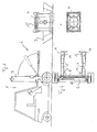
- Fig. 1 eine Seitenansicht eines Gabelstaplers mit hebbarer und auf die Gabelzinken absenkbarer Auflage,
- Fig. 2 eine Draufsicht auf das Hubgerüst des Gabelstaplers nach Fig. 1 mit auf den Gabeln ruhenden Auflagen,
- Fig. 3 eine Seitenansicht einer einen Gabelzinken einfassenden Auflage,
- Fig. 4 eine Draufsicht auf die Auflage nach Fig. 3,
- Fig. 5 eine Vorderansicht auf die Gabel mit der diese einfassenden Auflage nach den Fig. 3 und 4,
- Fig. 6 eine der Fig. 4 entsprechende Draufsicht auf einen austeleskopierbaren Gabelzinken mit mit dieser gekuppelten, ebenfalls teleskopierbar ausgebildeter Auflage,
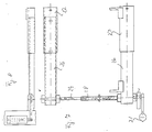
- Fig. 7 eine Draufsicht auf teleskopierbare Auflagen mit Schwenkeinrichtung und
- Fig. 8 eine Seitenansicht der Auflagen nach Fig. 7.
- Der in Fig. 1 dargestellte Gabelstapler 1 ist mit einer Zusatzeinrichtung 2 versehen, die dazu dient, den in die Auffangwanne 3 eingesetzten Behälter 4 für flüssige Sonderabfälle sicher erfassen, aus der Auffangwanne 3 herausheben und transportieren zu können. Bei dem Gabelstapler 1 sind die Gabelzinken 5, 6 in bekannter Weise in dem in dem Hubgerüst 7 in vertikaler Richtung verfahrbaren Gabelträger querverschieblich geführt. Zur Querverschiebung der Gabelzinken ist eine hydraulische Druckmittel-Kolbenzylinder-Einheit 9 vorgesehen. Weiterhin ist eine Gleichlaufführung vorhanden. Diese Ausgestaltung des Gabelstaplers 1 wird jedoch nicht näher beschrieben, da diese bekannt ist.
- Mit den Gabelzinken 5, 6 sind schwenkbar gelagerte Auflagen 10, 11 formschlüssig kuppelbar, die in ihren hinteren und vorderen Bereichen den Eckenkonturen des Behälters 4 angepaßte Formstücke 12 aufweisen. Um den Behälter 4 aufnehmen zu können, werden die Gabelzinken 5, 6 soweit auseinandergefahren, daß der Gabelstapler 1 mit seinen mit den Auflagen 10, 11 versehenen Zinken 5, 6 seitlich an dem Behälter 4 in der Weise vorbeifahren kann, daß dieser sich zwischen den Auflagen befindet. Anschließend werden die Zinken 5, 6 zusammengefahren, so daß die Formstücke 12 an den Ecken des Behälters 4 unterhalb von dessen oberen Randprofil 13 angreifen.
- In den Fig. 3 bis 5 ist eine den Gabelzinken 6 einfassende Auflage 14 näher dargestellt. Die Auflage 14 besteht aus einem U-Profil, dessen Schenkel im hinteren Bereich gabelförmig mit zwei Lagerlaschen 15 verschweißt sind. Mit der Bohrung der Lagerlaschen 15 ist ein Lagerbolzen 16 verschweißt, der in einer Lagerbuchse 17 drehbar gehalten ist, die mit dem Zinkenträger 18 verbunden ist, der auf dem Gabelträger querverschieblich geführt ist. Mit dem die Lagerlasche 15 überragenden Ende des Achszapfens 16 ist der Hebel 19 verbunden, der in dem Gabelstück 20 der Kolbenstange der hydraulischen Druckmittel-Kolbenzylinder-Einheit 21 gelagert ist. Das obere Ende des Zylinders der Druckmittel-Kolbenzylinder-Einheit 21 ist gelenkig mit dem Zinkenträger verbunden.
- Mit den vorderen und hinteren Bereichen der Auflage 14 sind Formstücke 12 verschweißt, die die Auflagen nach innen hin überragen und mit Ausschnitten versehen sind, deren Profil den Eckenkonturen des Behälters entspricht.
- Bei der Ausführungsform nach Fig. 6 sind austeleskopierbare Zinken vorgesehen. Dabei ist auf dem inneren Zinkenteil 24 das äußere Zinkenteil 25 teleskopartig geführt. Die Art der Ausbildung des teleskopierbaren Zinkens 24, 25 sowie der Teleskopierantrieb wird nicht näher erläutert, weil diese bekannter Art sind.
- Auf den austeleskopierbaren Zinken 24, 25 ist eine Auflage absenkbar, die ebenfalls aus austeleskopierbaren Teilen 26, 27 besteht. Das innere Teil 26 ist in der anhand der Fig. 3 bis 5 erläuterten Weise schwenkbar mit dem Zinkenträger verbunden. Das innere Teil 26 der Auflage wird von dem äußeren Teil 27 der Auflage übergriffen, wobei die unteren Enden der Schenkel des U-förmigen äußeren Teils 27 nach innen hin abgewinkelt sind, so daß eine C-förmige Führung der Schenkel des Teils 27 auf den Schenkein des Teils 26 gebildet ist. Das äußere Teil 27 ist auf der Unterseite seines Stegteils mit einem Zapfen 28 versehen, der in eine entsprechende Bohrung 29 des äußeren austeleskopierbaren Teils 25 der Zinken greift. Auf diese Weise ist das äußere austeleskopierbare Teil 27 der Auflage mit dem äußeren austeleskopierbaren Teil 25 der Zinken verbunden, so daß das äußere Teil 27 der Auflage die teleskopierende Bewegung der Zinken mitmacht.
- Die Teile 26, 27 der Auflage sind wiederum mit Formstücken 12 versehen, die einen kuppelnden Angriff an unterschiedlich große Behälter ermöglichen.
- Aus den Fig. 7 und 8 sind austeleskopierbare Auflagen ersichtlich. Die äußeren Auflagenteile 27 sind in der beschriebenen Weise auf den inneren Auflagenteilen 26 verschieblich geführt. Beide Auflagenteile weisen U-förmige Profile auf. Die inneren Auflagenteile 26 sind in der aus Fig. 7 ersichtlichen Weise durch teleskopierbare Rohrprofile 28, 29 miteinander verbunden, so daß nur ein Schwenkzylinder 21 vorgesehen zu werden braucht, weil die Schwenkbewegung von dem einen Auflagenteil 26 durch die teleskopierbaren Rohre 28, 29 auf das andere Auflagenteil 26 übertragen wird. Um die Drehbewegung übertragen zu können, können die teleskopierbaren Rohre 28, 29 Kastenprofile aufweisen.
Claims (7)
- Gabelstapler (1) mit in Führungen des Gabelträgers durch einen Antrieb (9) querverschieblichen Gabelzinken (5,6) und mit einer Zuzatzeinrichtung zum Ankuppeln von Behältern o. dgl., vorzugsweise zum Aufnehmen von Behältern (4) zur Lagerung gefährlicher Stoffe und Flüssigkeiten,
dadurch gekennzeichnet,
daß um den Fußbereich der Gabelzinken (5,6) schwenkbare hebelförmige Auflagen (14) vorgesehen sind, die durch einen Antrieb (21) von ihrer an das Hubgerüst (7) des Gabelstaplers (1) angeklappten inaktiven Stellung auf die Gabelzinken (5,6) absenkbar und formschlüssig mit diesen kuppelbar sind und die an ihren inneren einander zugewandten Seiten oder Bereichen Formstücke (12) und/oder Zapfen o.dgl. zum formschlüssigen Ankuppeln an die Behälter (4) aufweisen. - Gabelstapler nach Anspruch 1, dadurch gekennzeichnet, daß die Auflagen (14) ein U-förmigen Profil besitzen.
- Gabelstapler nach Anspruch 1 oder 2, dadurch gekennzeichnet, daß die Auflagen (14) im Fußbereich der Gabelzinken (5,6) gabelförmig mit Lagerlaschen (15) versehen sind, deren Lagerbohrungen ein an den Gabelzinlkenträgern (18) gehaltener Lagerbolzen durchsetzt.
- Gabelstapler nach einem der Ansprüche 1 bis 3, dadurch gekennzeichnet, daß mit den Lagerlaschen (15) oder den mit diesen festverbundenen Lagerbolzen (16) jeder Auflage (14) ein Hebel (19) verbunden ist, an dessen freiem Ende ein Ende einer Druckmittel-Kolbenzylinder-Einheit (21) angelenkt ist, deren anderes Ende an dem Gabelzinkenträger (18) angelenkt ist.
- Gabelstapler nach einem der Ansprüche 1 bis 4, dadurch gekennzeichnet, daß die Gabelzinken (24,25) in an sich bekannter Weise austeleskopierbar ausgebildet sind und daß die Auflägen (26,27) ebenfalls austeleskopierbar ausgebildet und die vorderen austeleskopierbaren Teile (27) Auflagen mit den entsprechenden vorderen austeleskopierbaren Teilen (25) der Gabelzinker formschlüssig kuppelbar sind.
- Gabelstapler nach Anspruch 5, dadurch gekennzeichnet, daß die vorderen austeleskopierbaren Teile (27) der Auflagen (26,27) Zapfen versehen sind, die an entsprechende Bohrungen der austeleskopierbaren Teile der Gabelzinken greifen.
- Gabelstapler nach einem der Ansprüche 1 bis 6, dadurch gekennzeichnet, daß die Formstücke (12) aus mit den Auflagen verbundenen Blechen oder Backen bestehen, deren die Auflagen nach innen hin überragenden Teile entsprechend den Eckenkonturen der Behälter (4) ausgeschnitten sind.
Priority Applications (1)
| Application Number | Priority Date | Filing Date | Title |
|---|---|---|---|
| AT89118130T ATE80589T1 (de) | 1988-10-27 | 1989-09-29 | Gabelstapler mit zusatzeinrichtung zum heben von behaeltern oder dergleichen. |
Applications Claiming Priority (2)
| Application Number | Priority Date | Filing Date | Title |
|---|---|---|---|
| DE8813516U DE8813516U1 (de) | 1988-10-27 | 1988-10-27 | Gabelstapler mit Zusatzeinrichtung zum Heben von Behältern o.dgl. |
| DE8813516U | 1988-10-27 |
Publications (2)
| Publication Number | Publication Date |
|---|---|
| EP0365865A1 EP0365865A1 (de) | 1990-05-02 |
| EP0365865B1 true EP0365865B1 (de) | 1992-09-16 |
Family
ID=6829330
Family Applications (1)
| Application Number | Title | Priority Date | Filing Date |
|---|---|---|---|
| EP89118130A Expired - Lifetime EP0365865B1 (de) | 1988-10-27 | 1989-09-29 | Gabelstapler mit Zusatzeinrichtung zum Heben von Behältern oder dergleichen |
Country Status (5)
| Country | Link |
|---|---|
| EP (1) | EP0365865B1 (de) |
| AT (1) | ATE80589T1 (de) |
| DE (2) | DE8813516U1 (de) |
| ES (1) | ES2034546T3 (de) |
| GR (1) | GR3005713T3 (de) |
Families Citing this family (3)
| Publication number | Priority date | Publication date | Assignee | Title |
|---|---|---|---|---|
| DE4100626C2 (de) * | 1991-01-11 | 1994-04-28 | Lengerich Maschf | Vorrichtung zum Entnehmen von Silagegut |
| DE19604123C2 (de) * | 1996-02-06 | 1998-07-02 | Paul Lingen | Modularer Manipulator zum Anschließen an fahrbare Arbeitsgeräte |
| FR2791049B1 (fr) | 1999-03-19 | 2001-06-01 | Sambron | Porte equipement pour engin de levage, mat d'un engin de levage comprenant un tel porte equipement et engin de levage tel que chariot a fourches pourvu dudit mat |
Family Cites Families (11)
| Publication number | Priority date | Publication date | Assignee | Title |
|---|---|---|---|---|
| US2584870A (en) * | 1948-06-15 | 1952-02-05 | John J Hally | Attachment for fork lift trucks |
| US2704167A (en) * | 1951-02-20 | 1955-03-15 | Yale & Towne Mfg Co | Drum handling attachment for lift trucks |
| GB760808A (en) * | 1953-08-04 | 1956-11-07 | John Reginald Sharp | Improvements in or relating to goods handling trucks |
| US2971662A (en) * | 1957-12-30 | 1961-02-14 | Clark Equipment Co | Box rotator attachment |
| DE1228563B (de) * | 1964-02-25 | 1966-11-10 | Hans Still Ges Mit Beschraenkt | Fassgreifer fuer Hublader |
| DE1902984U (de) * | 1964-07-28 | 1964-10-22 | Esslingen Maschf | Zur aufnahme und entleerung von behaeltern, insbesondere grubenfoerderwagen, vorgesehener kippgreifer zum anbau an hubwerken von flurfoerdermitteln. |
| FR2085472A1 (de) * | 1970-04-24 | 1971-12-24 | Guichard Jean | |
| US3797684A (en) * | 1972-05-02 | 1974-03-19 | V Brandt | Transporting and dumping apparatus |
| US3971485A (en) * | 1974-11-26 | 1976-07-27 | Thomas Hoppey | Forklift attachment |
| US4549845A (en) * | 1983-08-25 | 1985-10-29 | Automation Industries, Inc. | Method and apparatus for handling drums |
| DE8536516U1 (de) * | 1985-12-24 | 1986-04-17 | Spanset Inter AG, Zürich | Aufsatz für eine Gabelstaplerzinke |
-
1988
- 1988-10-27 DE DE8813516U patent/DE8813516U1/de not_active Expired
-
1989
- 1989-09-29 AT AT89118130T patent/ATE80589T1/de active
- 1989-09-29 ES ES198989118130T patent/ES2034546T3/es not_active Expired - Lifetime
- 1989-09-29 DE DE8989118130T patent/DE58902294D1/de not_active Expired - Fee Related
- 1989-09-29 EP EP89118130A patent/EP0365865B1/de not_active Expired - Lifetime
-
1992
- 1992-09-17 GR GR920401667T patent/GR3005713T3/el unknown
Also Published As
| Publication number | Publication date |
|---|---|
| ATE80589T1 (de) | 1992-10-15 |
| ES2034546T3 (es) | 1993-04-01 |
| GR3005713T3 (de) | 1993-06-07 |
| DE8813516U1 (de) | 1989-03-02 |
| EP0365865A1 (de) | 1990-05-02 |
| DE58902294D1 (de) | 1992-10-22 |
Similar Documents
| Publication | Publication Date | Title |
|---|---|---|
| DE2402704C2 (de) | Gabelstapler | |
| EP0726866B1 (de) | Grossraumtransportbehälter | |
| EP2415635B1 (de) | Transportwagen für den Transport von fahrbaren Behältern, insbesondere von fahrbaren Entsorgungsbehältern, sowie Verfahren zum staplerfreien Transport und Umschlag von fahrbaren Entsorgungsbehältern | |
| EP1415874B1 (de) | Batteriewechselsystem für ein Flurförderzeug | |
| EP1935731B1 (de) | Gabelstapler mit einer Führung zur seitlichen Batterieentnahme | |
| DE2203254C2 (de) | Palette, die als Transportplattform für Kraftfahrzeuge ausgebildet ist | |
| EP1396466B1 (de) | Flurförderzeug mit einer seitlichen Batterieentnahmeöffnung | |
| DE9418354U1 (de) | Lastklemmvorrichtung mit erweitertem vertikalem Bewegungsbereich | |
| DE3642700C2 (de) | ||
| EP2570358A2 (de) | Transportsystem für Transportbehälter oder Gitterboxen | |
| EP0379897B1 (de) | Transport- und/oder Handhabungsvorrichtung für Container oder dergleichen | |
| DE3620964A1 (de) | Vorrichtung zum ueberfuehren schwerer lasten von einem lagerort an einen anderen | |
| EP0365865B1 (de) | Gabelstapler mit Zusatzeinrichtung zum Heben von Behältern oder dergleichen | |
| EP0659627A2 (de) | Gabelhubwagen zum Heben und Senken sowie Transportieren von Lasten | |
| EP2953887B1 (de) | Vorrichtung zur aufnahme und zum transport von lasten | |
| DE3042174C2 (de) | ||
| DE202013102480U1 (de) | Handhabung von Coils | |
| EP0694481B1 (de) | Container für eine Containerentsorgungsanlage | |
| DE4218416C2 (de) | Anbaugerät für Flurförderzeuge | |
| DE4323328C2 (de) | Anbaugerät für Flurförderzeuge | |
| AT401911B (de) | Transportwaggon, insbesondere niederflurwagen | |
| DE3632031A1 (de) | Vorbaugeraet mit zwei verschiebbaren gabelzinken | |
| DE3701524C2 (de) | ||
| DE3617508A1 (de) | Maschine zum be- und entladen von paletten mit stueckguetern wie kisten, schachteln und dergleichen | |
| DE3514525A1 (de) | Verfahren und zubehoerteil zum entladen von fracht aus einem container |
Legal Events
| Date | Code | Title | Description |
|---|---|---|---|
| PUAI | Public reference made under article 153(3) epc to a published international application that has entered the european phase |
Free format text: ORIGINAL CODE: 0009012 |
|
| AK | Designated contracting states |
Kind code of ref document: A1 Designated state(s): AT BE CH DE ES FR GB GR IT LI LU NL SE |
|
| 17P | Request for examination filed |
Effective date: 19900528 |
|
| 17Q | First examination report despatched |
Effective date: 19910502 |
|
| GRAA | (expected) grant |
Free format text: ORIGINAL CODE: 0009210 |
|
| AK | Designated contracting states |
Kind code of ref document: B1 Designated state(s): AT BE CH DE ES FR GB GR IT LI LU NL SE |
|
| REF | Corresponds to: |
Ref document number: 80589 Country of ref document: AT Date of ref document: 19921015 Kind code of ref document: T |
|
| ITF | It: translation for a ep patent filed | ||
| REF | Corresponds to: |
Ref document number: 58902294 Country of ref document: DE Date of ref document: 19921022 |
|
| GBT | Gb: translation of ep patent filed (gb section 77(6)(a)/1977) | ||
| ET | Fr: translation filed | ||
| REG | Reference to a national code |
Ref country code: GR Ref legal event code: FG4A Free format text: 3005713 |
|
| REG | Reference to a national code |
Ref country code: ES Ref legal event code: FG2A Ref document number: 2034546 Country of ref document: ES Kind code of ref document: T3 |
|
| PLBE | No opposition filed within time limit |
Free format text: ORIGINAL CODE: 0009261 |
|
| STAA | Information on the status of an ep patent application or granted ep patent |
Free format text: STATUS: NO OPPOSITION FILED WITHIN TIME LIMIT |
|
| 26N | No opposition filed | ||
| PGFP | Annual fee paid to national office [announced via postgrant information from national office to epo] |
Ref country code: FR Payment date: 19930909 Year of fee payment: 5 |
|
| PGFP | Annual fee paid to national office [announced via postgrant information from national office to epo] |
Ref country code: GB Payment date: 19930913 Year of fee payment: 5 |
|
| PGFP | Annual fee paid to national office [announced via postgrant information from national office to epo] |
Ref country code: BE Payment date: 19930914 Year of fee payment: 5 |
|
| PGFP | Annual fee paid to national office [announced via postgrant information from national office to epo] |
Ref country code: SE Payment date: 19930916 Year of fee payment: 5 Ref country code: LU Payment date: 19930916 Year of fee payment: 5 Ref country code: GR Payment date: 19930916 Year of fee payment: 5 Ref country code: AT Payment date: 19930916 Year of fee payment: 5 |
|
| PGFP | Annual fee paid to national office [announced via postgrant information from national office to epo] |
Ref country code: ES Payment date: 19930927 Year of fee payment: 5 |
|
| PGFP | Annual fee paid to national office [announced via postgrant information from national office to epo] |
Ref country code: DE Payment date: 19930929 Year of fee payment: 5 |
|
| PGFP | Annual fee paid to national office [announced via postgrant information from national office to epo] |
Ref country code: NL Payment date: 19930930 Year of fee payment: 5 |
|
| PGFP | Annual fee paid to national office [announced via postgrant information from national office to epo] |
Ref country code: CH Payment date: 19931026 Year of fee payment: 5 |
|
| EPTA | Lu: last paid annual fee | ||
| PG25 | Lapsed in a contracting state [announced via postgrant information from national office to epo] |
Ref country code: LU Free format text: LAPSE BECAUSE OF NON-PAYMENT OF DUE FEES Effective date: 19940929 Ref country code: GB Effective date: 19940929 Ref country code: AT Effective date: 19940929 |
|
| PG25 | Lapsed in a contracting state [announced via postgrant information from national office to epo] |
Ref country code: SE Effective date: 19940930 Ref country code: LI Effective date: 19940930 Ref country code: ES Free format text: LAPSE BECAUSE OF THE APPLICANT RENOUNCES Effective date: 19940930 Ref country code: CH Effective date: 19940930 Ref country code: BE Effective date: 19940930 |
|
| EAL | Se: european patent in force in sweden |
Ref document number: 89118130.7 |
|
| BERE | Be: lapsed |
Owner name: EDELHOFF POLYTECHNIK G.M.B.H. & CO. Effective date: 19940930 |
|
| PG25 | Lapsed in a contracting state [announced via postgrant information from national office to epo] |
Ref country code: GR Free format text: THE PATENT HAS BEEN ANNULLED BY A DECISION OF A NATIONAL AUTHORITY Effective date: 19950331 |
|
| PG25 | Lapsed in a contracting state [announced via postgrant information from national office to epo] |
Ref country code: NL Effective date: 19950401 |
|
| NLV4 | Nl: lapsed or anulled due to non-payment of the annual fee | ||
| GBPC | Gb: european patent ceased through non-payment of renewal fee |
Effective date: 19940929 |
|
| PG25 | Lapsed in a contracting state [announced via postgrant information from national office to epo] |
Ref country code: FR Effective date: 19950531 |
|
| REG | Reference to a national code |
Ref country code: CH Ref legal event code: PL Ref country code: GR Ref legal event code: MM2A Free format text: 3005713 |
|
| PG25 | Lapsed in a contracting state [announced via postgrant information from national office to epo] |
Ref country code: DE Effective date: 19950601 |
|
| EUG | Se: european patent has lapsed |
Ref document number: 89118130.7 |
|
| REG | Reference to a national code |
Ref country code: FR Ref legal event code: ST |
|
| REG | Reference to a national code |
Ref country code: ES Ref legal event code: FD2A Effective date: 19991007 |
|
| PG25 | Lapsed in a contracting state [announced via postgrant information from national office to epo] |
Ref country code: IT Free format text: LAPSE BECAUSE OF NON-PAYMENT OF DUE FEES;WARNING: LAPSES OF ITALIAN PATENTS WITH EFFECTIVE DATE BEFORE 2007 MAY HAVE OCCURRED AT ANY TIME BEFORE 2007. THE CORRECT EFFECTIVE DATE MAY BE DIFFERENT FROM THE ONE RECORDED. Effective date: 20050929 |